LiftMaster T T-LOGIC 3 Manual
LiftMaster T Manual
 |
View all LiftMaster T manuals
Add to My Manuals
Save this manual to your list of manuals |
LiftMaster T manual content summary:
- LiftMaster T | T-LOGIC 3 Manual - Page 1
the (MAS) Maintenance Alert System LED. An LED on the 3-button station will signal when the set number of cycles/months is reached or when the operator requires immediate service. INTENDED FOR PROFESSIONAL INSTALLATION ONLY Visit www.LiftMaster.com to locate a professional installing dealer in your - LiftMaster T | T-LOGIC 3 Manual - Page 2
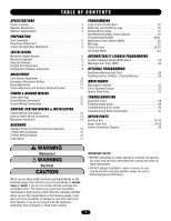
Device Options 19 Programming Remotes 20-21 Maintenance Alert System (MAS 22 Mid Stop 23 Timer To Close 23-24 Car Dealer Mode 24 AUTOMATICALLY LEARNED PROGRAMMING Auxiliary Reversal System/RPM Sensor 25 Maximum Run Timer (MRT 25 OPTIONAL PROGRAMMING Red/Green Warning Light Card 26 Resetting - LiftMaster T | T-LOGIC 3 Manual - Page 3
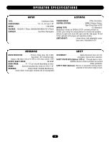
. DESCRIPTION POWERHEAD ASSEMBLY OWNER'S MANUAL AND CAUTION LABELS HARDWARE BOX (INCLUDES FASTENERS, TRACK SPACERS, TROLLEY, DOOR ARM ASSEMBLY, FRONT IDLER AND HEADER MOUNTING BRACKET) 3-BUTTON CONTROL STATION WITH LED TROLLEY DRIVE CHAIN (#48 FOR 1/3 & 1/2 HP, #41 FOR 3/4 HP AND HIGHER) NOTE - LiftMaster T | T-LOGIC 3 Manual - Page 4
close with open override. See pages 18 and 19 for optional wiring types and operating modes. LIMIT ADJUST Linear driven, fully adjustable screw type cams. Adjustable to 24'. MECHANICAL DRIVE REDUCTION Primary: Heavy duty (5L) V-Belt Secondary: #41 chain/sprocket; Output: #48 chain (1/3 & 1/2 HP - LiftMaster T | T-LOGIC 3 Manual - Page 5
until instructed to do so. • If the door lock needs to remain functional, install an interlock switch. • ALWAYS call a trained professional door serviceman if door binds, sticks or is out of balance. An unbalanced door may not reverse when required. • NEVER try to loosen, move or adjust doors, door - LiftMaster T | T-LOGIC 3 Manual - Page 6
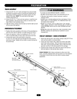
operator to a horizontal position above the guide rails and temporarily secure with a suitable rope, chain, or support from the floor. Open door slowly, being careful not to dislodge the temporary support. Using the door as a support, place a level against the rail and shim the operator until it is - LiftMaster T | T-LOGIC 3 Manual - Page 7
supports of the garage. Concrete anchors MUST be used if installing ANY brackets into masonry. STRAIGHT ARM ATTACHMENT 1. Fully close the door and move the trolley slider to within 2" of the front idler. 2. Latch the straight door arm to the fixed roll pin in the trolley carriage. Make sure the open - LiftMaster T | T-LOGIC 3 Manual - Page 8
electrical box in accordance with local codes. To prevent possible SEVERE INJURY or DEATH, install reversing sensors when: CAUTION • The radio is used. • The 3-button control station is out of sight of the door. • Or ANY other control (automatic or manual) is used. Reversing devices are recommended - LiftMaster T | T-LOGIC 3 Manual - Page 9
the door even with top of door opening. 4. Repeat steps 1 and 2 for close cycle. Adjust close limit nut so that the limit switch is engaged as door fully seats at the floor. WARNING To avoid SERIOUS personal INJURY or DEATH from electrocution, disconnect electric power BEFORE manually moving limit - LiftMaster T | T-LOGIC 3 Manual - Page 10
door control or remote. Emergency Disconnect Door Arm Lift free end of door arm to trolley. Pull emergency handle to allow arm to engage roll pin. Release handle. Emergency disconnect will close. Clevis Pin ATTENTION Emergency Chain Disconnect Straight Door Arm Assembly Door Bracket Door - LiftMaster T | T-LOGIC 3 Manual - Page 11
possible to stop the door by hand during travel. 4. Reinstall cotterpin. WARNING To prevent possible SEVERE INJURY or DEATH, install reversing sensors when: CAUTION • The radio is used. • The 3-button control station is out of sight of the door. • Or ANY other control (automatic or manual) is used - LiftMaster T | T-LOGIC 3 Manual - Page 12
service. • Disconnect power at the fuse box BEFORE proceeding. Operator MUST be properly grounded and connected in accordance with local electrical codes. The operator should be on a separate fused line location of the power disconnect should be visible and clearly labeled. • ALL power and control - LiftMaster T | T-LOGIC 3 Manual - Page 13
AC 13 24 VOLT AC TIMER DEFEAT 12 TIMER DEFEAT CMN 11 COMMON AVEMRASTI1S0 SMAEINMTENEANNCETALERT SYSTEM EYES 9 PHOTO EYES (LiftMaster Only) ATTEDGEE N8TRIEOVENRSE OPEN 7 OPEN CLOSE 6 CLOSE STOP 5 STOP CMN 4 COMMON 3 INTERLOCK 2 INTERLOCK SBC 1 SINGLE BUTTON CONTROL ADVERTENCIA PRECAUCIÓNOR IN THE - LiftMaster T | T-LOGIC 3 Manual - Page 14
DIAGRAMS Radio Control (24V DC only) CPS-L & CPS-LN4 R3 R2 R1 Sensing Edge Timer Defeat Switch Maintenance Alert LED (RD) (WH) Open Close Stop Open/Close Single Button OPEN CLOSE STOP 3-Button Station Remove Jumper To Install External Interlock Single Phase Power Wiring Line Power 115 - LiftMaster T | T-LOGIC 3 Manual - Page 15
SWITCH (YE) (BL) Maintenance Alert LED (RD) (WH) Open Close Stop OPEN CLOSE STOP 3-Button Station Open/Close Single Button Remove Jumper To Install External Door Interlock MAS 10 EYES 9 EDGE 8 OPEN 7 CLOSE 6 STOP 5 CMN 4 3 2 SBC 1 F 1 D31 D 7 D 6 D 5 D 4 24V AC 14 24V AC 13 TIMER DEFEAT - LiftMaster T | T-LOGIC 3 Manual - Page 16
SWITCH (YE) (BL) Maintenance Alert LED (RD) (WH) Open Close Stop OPEN CLOSE STOP 3-Button Station Open/Close Single Button Remove Jumper To Install External Door Interlock MAS 10 EYES 9 EDGE 8 OPEN 7 CLOSE 6 STOP 5 CMN 4 3 2 SBC 1 F 1 D31 D 7 D 6 D 5 D 4 24V AC 14 24V AC 13 TIMER DEFEAT - LiftMaster T | T-LOGIC 3 Manual - Page 17
MAS 10 EYES 9 EDGE 8 OPEN 7 CLOSE 6 STOP 5 CMN 4 3 2 SBC 1 F1 C54 C71 C78 ® Motor Direction Jumper Single Phase & Three Phase Jumper Maintenance Alert System Button for Programming Open Button Close Button Stop Button Control Wiring Terminal Block Wiring Type Selector Dial Failsafe Switch 17 - LiftMaster T | T-LOGIC 3 Manual - Page 18
component locations. Before programming the logic board, set the operators open and close limits. LEDs on the logic board are provided to assist setting the limits. As each limit is activated the corresponding LED will light up. The abbreviations are Open Limit Switch (OLS), Close Limit Switch (CLS - LiftMaster T | T-LOGIC 3 Manual - Page 19
open limit bypassing the mid stop and activates the Timer To Close, putting the operator in TS mode until the door reaches the down limit, or is stopped in travel. At which time the operator enters the B2 mode. Compatible with 3-Button Station, 1-Button Station and 1- and 3-Button Remote Controls - LiftMaster T | T-LOGIC 3 Manual - Page 20
to Close start/refresh only, bypassing a programmed Open Mid-Stop. 1. Press and release the RADIO button on the logic board (LED will light). 2. Press and release the SBC externally wired button or TIMER on the logic board (LED flashes rapidly and then remains on solid). 3. Press and hold the remote - LiftMaster T | T-LOGIC 3 Manual - Page 21
D14 P1 D34 D31 D7 D6 D5 D4 24V AC 14 24V AC 13 TIMER DEFEAT 12 CMN 11 MAS 10 EYES 9 EDGE 8 OPEN 7 CLOSE 6 STOP 5 CMN 4 3 2 SBC 1 F1 REMOTE CONTROL PROGRAMMING FEATURE Program Remote Controls from the 3-button control station (3BCS). Requires Firmware Version 4.6 or higher and a 3BCS with the MAS - LiftMaster T | T-LOGIC 3 Manual - Page 22
be used to troubleshoot some problems with the operator. Benefit: The Maintenance Alert System (MAS) assists the installing dealer in setting up a routine maintenance program. Once programmed, the MAS notifies the end user (with a flashing LED on the 3-button station) when a preset number of cycles - LiftMaster T | T-LOGIC 3 Manual - Page 23
other safety devices will not open the door beyond the mid stop position, except in E2 mode. The Timer to Close will work from the Mid Stop. To clear the Mid Stop set the selector dial to Program and press and hold the MID SET button for 5 seconds. The MID SET LED will flash rapidly and turn off - LiftMaster T | T-LOGIC 3 Manual - Page 24
CLOSE LED will flash once for every 60 seconds programmed. To deactivate the timer from the open position press the STOP button. The timer will be reactivated on the next operation command. To deactivate the timer for more than one cycle, attach a switch to 11 & 12 (Common and Timer Defeat). All - LiftMaster T | T-LOGIC 3 Manual - Page 25
. (Auxiliary Reversal System not applicable on models GH and GT.) NOTE: This feature is automatically learned and does not require programming. LOSE OPEN RPM Sensor Logic Board MAXIMUM RUN TIMER (MRT) Feature: The operator can learn the time it takes to open or close the door plus and an - LiftMaster T | T-LOGIC 3 Manual - Page 26
Advanced warning of the door closing helps prevent traffic collisions with the door. Light Control Module Operation: The green lights on the OPTION BOARD will turn on if the board is seated properly and the power is on. When the door reaches the full open limit or mid stop, the timer circuit and the - LiftMaster T | T-LOGIC 3 Manual - Page 27
has been in service. 1. Start with the door in the closed position. 2. Turn the SELECTOR DIAL to DIAG (diagnostic mode). 3. Press and release the MAS button on the logic board. 4. Press and release the MRT button on the logic board. 5. The open and close lights will flash. OPEN for every 5,000 - LiftMaster T | T-LOGIC 3 Manual - Page 28
will activate from open or mid stop position. Flashing indicates Timer is counting down and door will close after preset time. Indicates a closed circuit between common and terminal 1. Pressing the single button control station should turn ON this LED. Indicates the Maintenance Alert System has been - LiftMaster T | T-LOGIC 3 Manual - Page 29
➤ Replace RPM sensor. THE DOOR WILL MOVE MOST OF THE WAY TOWARDS A LIMIT THEN STOP. AN EXTRA OPEN OR CLOSE COMMAND IS ABLE TO GET DOOR TO COMPLETE CYCLE The Maximum Run Timer is not set correctly THE DOOR WILL OPEN SOME BUT NOT COMPLETELY. AN EXTRA OPEN IS ABLE TO GET THE DOOR TO OPEN COMPLETELY - LiftMaster T | T-LOGIC 3 Manual - Page 30
verify RPM sensor connection or replace RPM sensor. NOTE: To relearn the RPM sensor, move the door with a constant pressure command. The door will stop once relearned and normal operation will resume. First check Operator for any faults (i.e., Bad Limit switch), manually learn Max Run Timer (page 25 - LiftMaster T | T-LOGIC 3 Manual - Page 31
CODE SYMPTOM R1 No response from the remote R2 No response from the remote R3 The remote cannot be learned R4 The remote cannot be learned R5 The remote cannot be learned R6 Cannot close via constant pressure in C2, D1 or E2 modes. DISPLAY POSSIBLE PROBLEM CORRECTION Quick Flash - LiftMaster T | T-LOGIC 3 Manual - Page 32
ELECTRICAL BOX 6 5 9 10 4 7 2 3 K2 (K72-12515-1) 11 8 1 K1 (K72-10047-1) 32 - LiftMaster T | T-LOGIC 3 Manual - Page 33
SERVICE KITS ITEM K1 K2 PART # K72-10047 K72-10047-1 K72-12515-1 DESCRIPTION Limit shaft kit Limit shaft kit (3 HP) Complete with: Limit shaft, limit nuts, limit bearings, limit sprocket, interrupter cup, shim washers, compression ring, roll pin, and e-rings. Limit switch kit Complete with: Limit - LiftMaster T | T-LOGIC 3 Manual - Page 34
MODEL T 22 19 20 21 18 K5 (K75-1287K05) K4 (K72-12508 K72-12509) 12 18 13 12 14 16 15 17 3 10 8 5 9 6 7 K3 (K72-12507 K72-12506) 5 11 4 K3 23 K1 (71-B120 71-B240) 2 1 K2 (K75-10177) 34 - LiftMaster T | T-LOGIC 3 Manual - Page 35
, limit chain, shim washers, roll pins, push ring 3/4" and sprockets (41B32 & 48B10). Output shaft kit (3/4 & 1 HP) Complete with: Same as kit above. Door arm kit Complete with: Curved arm, straight arm, door bracket and hardware. NOT SHOWN DOOR DRIVE CHAIN KITS DOOR HEIGHT Doors 8' to 10' Doors - LiftMaster T | T-LOGIC 3 Manual - Page 36
3 POSITION KEYSWITCH WITH SPRING RETURN TO CENTER STANDARD 764 764 2 OR MORE Keyswitch D1 & E2 MODE ONLY Open See note 2. Close 1 BUTTON STATION OR ANY AUXILIARY DEVICE OPEN / CLOSE 14 B2, T, TS & FSTS MODE ONLY See note 2. Open Open Close Close RADIO CONTROLS OPEN / CLOSE R1 R2 R3 D1
-
 1
1 -
 2
2 -
 3
3 -
 4
4 -
 5
5 -
 6
6 -
 7
7 -
8
-
9
-
10
-
11
-
12
-
13
-
14
-
15
-
16
-
17
-
18
-
19
-
20
-
21
-
22
-
23
-
24
-
25
-
26
-
27
-
28
-
29
-
30
-
31
-
32
-
33
-
34
-
35
-
36
 |
 |

O W N E R ’ S M A N U A L
T
INDUSTRIAL DUTY COMMERCIAL DOOR OPERATOR
ogic
L
3
NOT FOR RESIDENTIAL USE
A
L
E
R
T
S
Y
S
T
E
M
M
A
I
N
T
E
N
A
N
C
E
PATENT PENDING
The Maintenance Alert System™ allows the
installer to set an internal Maintenance
Cycle Counter. The Logic 3 operator
incorporates a self-diagnostic feature built
into the (MAS) Maintenance Alert System
LED. An LED on the 3-button station will
signal
when
the
set
number
of
cycles/months is reached or when the
operator requires immediate service.
This Operator Features
the Enhanced
Radio Receiver
Built on Board
Serial # Box
Installation Date
2
YEAR
WARRANTY
315MHz
Visit www
.LiftMaster
.com
to locate a professional installing dealer in your area.
INTENDED FOR PROFESSIONAL
INSTALLATION ONLY
A SAFETY DEVICE IS HIGHLY RECOMMENDED