LiftMaster T T LOGIC CONTROL VERSION 2 Manual
LiftMaster T Manual
 |
View all LiftMaster T manuals
Add to My Manuals
Save this manual to your list of manuals |
LiftMaster T manual content summary:
- LiftMaster T | T LOGIC CONTROL VERSION 2 Manual - Page 1
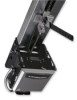
OWNER'S MANUAL MODEL T LOGIC CONTROL (VER. 2.0) INDUSTRIAL DUTY DOOR OPERATOR LOGIC LCONTROL FACTORYSET C2 Wiring See pages 15 & 16 for other wiring configurations PATENT PENDING The Maintenance Alert System™ allows the installer to set an internal Maintenance Cycle Counter. An LED on the 3-button - LiftMaster T | T LOGIC CONTROL VERSION 2 Manual - Page 2
16 RPM Sensor 17 Maximum Run Timer 17 Maintenance Alert System 18 OPTIONAL PROGRAMMING Mid Stop 18 Timer to Close 19 Red Green Warning Lights 19 Board Illustration 20 REPLACEMENT PARTS & MAINTENANCE Trouble Shooting Guide 21 & 22 Maintenance Schedule 23 Customer Service Contact Information - LiftMaster T | T LOGIC CONTROL VERSION 2 Manual - Page 3
modes. LIMIT ADJUST Linear driven, fully adjustable screw type cams. Adjustable to 24 feet. MECHANICAL DRIVE REDUCTION Primary: Heavy duty (5L) V-Belt. Secondary: #41 chain/sprocket. Output: #48 chain (1/3 &1/2HP) or #41 chain (3/4 &1HP) OUTPUT SHAFT SPEED: . . . .140 R.P.M. DOOR SPEED 11 - LiftMaster T | T LOGIC CONTROL VERSION 2 Manual - Page 4
to the drive shaft sprocket, and then to the take-up bolt on the carriage. Front Idler Assembly 3. Using the other master link, attach the chain to the take-up bolt and tighten to the desired chain tension. Reel chain around idler and over spacer brackets Chain Tension: With trolley positioned - LiftMaster T | T LOGIC CONTROL VERSION 2 Manual - Page 5
shaped) front header bracket to the pad. 3.50" 1.75" Cotterpins Pivot Shaft 2. Swing the operator to a horizontal position above the guide rails and temporarily secure with a suitable rope, chain, or support from the floor. Now open garage door slowly, being careful not to dislodge the temporary - LiftMaster T | T LOGIC CONTROL VERSION 2 Manual - Page 6
than 15 feet, use of a midspan support is recommended. STRAIGHT ARM ATTACHMENT 1. Fully close the door and move the trolley slider to within (2") two inches of the front idler. 2. Latch the straight door arm to the fixed roll pin in the trolley carriage. Make sure the open side of notch on the arm - LiftMaster T | T LOGIC CONTROL VERSION 2 Manual - Page 7
as door fully seats at the floor. WARNING TO AVOID SERIOUS PERSONAL INJURY OR DEATH FROM CAUTION ELECTROCUTION, DISCONNECT ELECTRIC POWER BEFORE MANUALLY MOVING LIMIT NUTS. If other problems persist, call our toll-free number for assistance: 1-800-528-2806. CLOSE Limit Switch OPEN Limit Switch - LiftMaster T | T LOGIC CONTROL VERSION 2 Manual - Page 8
TIME THE UNIT MAY BE RETURNED TO SERVICE. WARNIWNGARNING TO AVOID DAMAGE TO DOOR AND OPERATOR, MAKE ALL DOOR LOCCKSAINOUPETRAITOICVEN.ASEUCUTREILOOCNK(S) IN "OPEN" POSITION. IF THE DOOR LOCK NEEDS TO REMAIN FUNCTIONAL, INSTALL AN INTERLOCK SWITCH. WARNIWNGARNING DISCONNECT POWER AT THE FUSE BOX - LiftMaster T | T LOGIC CONTROL VERSION 2 Manual - Page 9
Maintenance Alert System™ Optional If light is Flashing Controls it is time for routine Door and Opener Maintenance. If light is Steady On, call for immediate service. Service every _______ cycles. RADIO CONTROLS On all models with B2 control wiring, a terminal bracket marked R1 R2 R3 is located on - LiftMaster T | T LOGIC CONTROL VERSION 2 Manual - Page 10
release. WARNING WARNING Header Bracket Trolley Track Clevis Pin Emergency Disconnect Door Bracket Straight Door Arm Assembly Chain Curved Door Door Arm NOTICE Emergency Release Handle TO DISCONNECT DOOR FROM OPENER Emergency Disconnect Door Arm Pull emergency release handle straight - LiftMaster T | T LOGIC CONTROL VERSION 2 Manual - Page 11
door by hand during travel. 4. Reinstall Cotterpin. The Auxiliary Reversal System works in tandem with the adjustable clutch to detect if a closing door meets an obstruction. If an obstruction is met and causes the clutch to slip, the Auxiliary Reversal System will return the door to the full open - LiftMaster T | T LOGIC CONTROL VERSION 2 Manual - Page 12
STANDARD POWER & CONTROL CONNECTION DIAGRAM Logic Control Board (VER. 2.0) - 115V, 208, 230V, 1Ph Logic Control Board (VER. 2.0) - 115V, 208, 230V, 1Ph Logic Control Board (VER. 2.0) - 208, 230V, 380V, 460V, 3Ph 12 - LiftMaster T | T LOGIC CONTROL VERSION 2 Manual - Page 13
SEE OWNER'S MANUAL FOR DIP SWITCH FUNCTIONS AND PROGRAMMING PROCEDURES. 2) TO REVERSE MOTOR DIRECTION 115 VOLTS: ALWAYS EXCHANGE PURPLE AND GREY ALL VOLTS & PHASES. 230 VOLTS: INTERCHANGE PURPLE (E10) & GREY (E15) WIRES AT LOGIC BOARD. 3) TRANSFORMER PRIMARY VOLTAGE SAME AS LINE VOLTAGE. 4) SINGLE - LiftMaster T | T LOGIC CONTROL VERSION 2 Manual - Page 14
3) NOTES: 1) SEE OWNER'S MANUAL FOR DIP SWITCH FUNCTIONS AND PROGRAMMING PROCEDURES. 2) TO REVERSE MOTOR DIRECTION: INTERCHANGE ANY 2 OF THE 3 POWER WIRES AT L1, L2 & L3, OR EXCHANGE PURPLE (E17) & GREY (E16) WIRES AT LOGIC BOARD. 3) TRANSFORMER PRIMARY VOLTAGE SAME AS LINE VOLTAGE. 4) THREE PHASE - LiftMaster T | T LOGIC CONTROL VERSION 2 Manual - Page 15
), Close Limit Switch (CLS) and Sensing Limit Switch (SLS). Refer to page 7 for limit switch adjustment instructions. Logic Control Pushbuttons Open, Close, Stop Open, Close and Stop buttons are mounted directly on the Logic Control board. This will provide easy programming ability and door control - LiftMaster T | T LOGIC CONTROL VERSION 2 Manual - Page 16
controls allowing open, close and stop. User set midstop. User set Timer To Close. The single button station opens the door to the full open limit bypassing the mid stop and activates the Timer To Close, putting the operator in TS mode until the door reaches the down limit, or is stopped in travel - LiftMaster T | T LOGIC CONTROL VERSION 2 Manual - Page 17
. LiftMaster recommends the use of safety devices for primary safety protection. To Program: 1. The open and close limits must be set before setting the RPM sensor. 2. Start with the door closed and turn all dip-switches to the off position. 3. Press open then press and hold the "learn" button - LiftMaster T | T LOGIC CONTROL VERSION 2 Manual - Page 18
maintenance on the door or operator. To Program: 1. Close the door. 2. Set the dip switches to "set Maintenance Alert System" 3. Press "close" to zero out the counter. 4. Press "open" for every 5,000 cycles the operator should wait before flashing the LED. 5. Return the dip switches to your regular - LiftMaster T | T LOGIC CONTROL VERSION 2 Manual - Page 19
the amount of time that a warning light will flash before the Timer To Close will activate the door to close. Benefit: Advanced warning of door closure helps prevent traffic collisions with the door. To Program: 1. Set the dip switches to "Set Timer To Close" 2. Press stop for every additional - LiftMaster T | T LOGIC CONTROL VERSION 2 Manual - Page 20
LOGIC 2.0 PCB BOARD ILLUSTRATION RPM Learn Button (see page 16) Power Wiring Terminal Block (see pages 8-9) Dip Switch (see pages 8-9) Control Wiring Terminal Block (see pages 8-9) Open, Close, Stop Buttons 20 - LiftMaster T | T LOGIC CONTROL VERSION 2 Manual - Page 21
b) Motor is malfunctioning RESOLUTION Reset the RPM sensor. Also verify that the software is version 260 or better. Order replacement chips from Parts and Service. Reset the Maximum Run Timer Reset the mid-stop by programming it to be at the open limit. a) Remove the obstruction, check the safety - LiftMaster T | T LOGIC CONTROL VERSION 2 Manual - Page 22
as each control button is pressed. The LEDs should light with each Open, Close, and Single Button Control command. The Stop should turn off the LED. 3. Activate the limit switches to verify functionality. Also watch the LEDs during door travel to check for over active limit switches. 4. Disconnect - LiftMaster T | T LOGIC CONTROL VERSION 2 Manual - Page 23
through Friday 8:00 A.M. TO 4:30 P.M. - Saturday www.liftmaster.com WHEN ORDERING REPAIR PARTS, ALWAYS GIVE THE FOLLOWING INFORMATION: • PART NUMBER • PART NAME • MODEL NUMBER ADDRESS ORDERS TO: THE CHAMBERLAIN GROUP, INC. Technical Support Group 6020 S. Country Club Road Tucson, Arizona 85706 23 - LiftMaster T | T LOGIC CONTROL VERSION 2 Manual - Page 24
ILLUSTRATED PARTS - ELECTRICAL BOX S6 S5 S2 10 S7 S1 S8 S4 S9 5 S3 L3 L1 L9 6 7 L8 L5 L8 L6 L2 2 1 3 24 L7 4 8 9 L2 L6 L4 4 - LiftMaster T | T LOGIC CONTROL VERSION 2 Manual - Page 25
prefix to the model number of your operator. For example: T5011L (Operator) = K-T5011L (Electrical box replacement kit) Electrical Box Sub-Assemblies K72-13912 Limit Shaft Assembly K72-12514 Limit Switch Assembly Motor Kits K20-1033B2L Models T3311L, T3321L K20-3033B4 Models T3323L, T3338L - LiftMaster T | T LOGIC CONTROL VERSION 2 Manual - Page 26
ILLUSTRATED PARTS - MODEL T H4 H6 H8 H3 H5 TRACK DRIVE CHAIN O11 O2 O3 O9 H2 O1 O8 H7 10-10030 O10 C16 H1 O2 O4 O8 10-10011M1 O9 C3 C2 C13 C10 C14 O5 - LiftMaster T | T LOGIC CONTROL VERSION 2 Manual - Page 27
Dia. x 1-1/2" Long 1 O11 87-P-075 Push Ring, 3/4" I.D. 1 DOOR HEIGHT Doors to 8' Doors to 10' Doors to 12' Doors to 14' Doors to 16' Doors to 18' Doors to 20' Doors to 22' Doors to 24' DOOR TRACK AND DRIVE CHAIN KITS DOOR TRACK DOOR DRIVE CHAIN PART # 10-5808 10-5810 10-5812 10-5814 10-5816 - LiftMaster T | T LOGIC CONTROL VERSION 2 Manual - Page 28
3 POSITION KEYSWITCH WITH SPRING RETURN TO CENTER STANDARD 764 764 2 OR MORE Open D1 & E2 MODE ONLY Close See Note 1 BUTTON STATION OR ANY AUXILIARY DEVICE OPEN / CLOSE 14 B2, T, TS & FSTS MODE ONLY See Note Open Open D1 & E2 MODE ONLY Close Close RADIO CONTROLS OPEN / CLOSE R1 R2 R3
-
 1
1 -
 2
2 -
 3
3 -
 4
4 -
 5
5 -
 6
6 -
 7
7 -
8
-
9
-
10
-
11
-
12
-
13
-
14
-
15
-
16
-
17
-
18
-
19
-
20
-
21
-
22
-
23
-
24
-
25
-
26
-
27
-
28
 |
 |

LOGIC CONTROL
L
C2 Wiring
F A C T O R Y S E T
See pages 15 & 16
for other wiring
configurations
Serial #
(located on electrical box cover)
Installation Date
Wiring Type
2
YEAR
WARRANTY
PATENT PENDING
The Maintenance Alert System™
allows the installer to set an internal
Maintenance Cycle Co
u
nter.
An LED
on the 3-b
u
tton station will signal when
the set n
u
mber of cycles is reached or
when the opener req
u
ires immediate
service.
NOT FOR RESIDENTIAL USE
OWNER’S MANUAL
MODEL T
LOGIC CONTROL (VER. 2.0)
INDUSTRIAL DUTY DOOR OPERATOR