LiftMaster T T- Mechanical New style with thermal overload Manual
LiftMaster T Manual
 |
View all LiftMaster T manuals
Add to My Manuals
Save this manual to your list of manuals |
LiftMaster T manual content summary:
- LiftMaster T | T- Mechanical New style with thermal overload Manual - Page 1
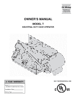
OWNER'S MANUAL MODEL T INDUSTRIAL DUTY DOOR OPERATOR FACTORY SET C2 Wiring See page 8 for other wiring configurations 2 YEAR WARRANTY Serial # (located on electrical box cover) Installation Date Wiring Type NOT FOR RESIDENTIAL USE - LiftMaster T | T- Mechanical New style with thermal overload Manual - Page 2
to CLOSE, open override plus wiring for sensing device to reverse. See page 8 for optional control settings. LIMIT ADJUST Linear driven, fully adjustable screw type cams. Adjustable to 24 feet. MECHANICAL DRIVE REDUCTION Primary: Heavy duty (5L) V-Belt. Secondary: #41 chain/sprocket. Output - LiftMaster T | T- Mechanical New style with thermal overload Manual - Page 3
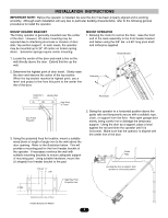
brackets, back to the drive shaft sprocket, and then to the take-up bolt on the carriage. FRONT IDLER ASSEMBLY 3. Using the other master link, attach the chain to the takeup bolt and tighten to the desired chain tension. Front Idler Assembly Chain Tension: With trolley positioned at either end - LiftMaster T | T- Mechanical New style with thermal overload Manual - Page 4
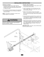
to the pad. 3.50" 1.75" 2. Swing the operator to a horizontal position above the guide rails and temporarily secure with a suitable rope, chain, or support from the floor. Now open garage door slowly, being careful not to dislodge the temporary support. Using the door as a support, place a level - LiftMaster T | T- Mechanical New style with thermal overload Manual - Page 5
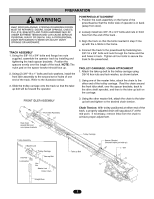
INSTALLATION INSTRUCTIONS CAUTION WARNING OPERATOR SUPPORT STRAIGHT ARM ATTACHMENT 1. The illustration below shows a typical method of 1. Fully close the door and move the trolley slider to within hanging the operator from the ceiling. Each installation (2") two inches of the front idler. - LiftMaster T | T- Mechanical New style with thermal overload Manual - Page 6
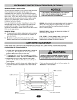
as door fully seats at the floor. WARNING TO AVOID SERIOUS PERSONAL INJURY OR DEATH FROM ELECTROCUTION, DISCONNECT ELECTRIC POWER BEFORE MANUALLY MOVING LIMIT NUTS. If other problems persist, call our toll-free number for assistance: 1-800-528-2806. CLOSE Limit Switch OPEN Limit Switch Actuator - LiftMaster T | T- Mechanical New style with thermal overload Manual - Page 7
power supply will cause the motor to rotate in the wrong direction (open when CLOSE button is pressed and vice-versa). To correct this, interchange any two of the incoming three phase power lines. CONDUIT ACCESS WARNING Do Not Run Power & Control Wiring in the Same Conduit 7/8" Dia Knockouts for - LiftMaster T | T- Mechanical New style with thermal overload Manual - Page 8
operator, contact the customer service department: 1-800-528-2806. LOCATING THE CONTROL STATION All operators are supplied with some type of control station. Generally a three button station (OPEN/CLOSE/STOP) is provided. A two-position key switch or control station (OPEN/CLOSE) may be added or - LiftMaster T | T- Mechanical New style with thermal overload Manual - Page 9
DUE TO THE USER'S ABILITY TO OPEN OR CLOSE THE DOOR WHEN OUT OF SIGHT OF THE DOOR. IN ADDITION, IF A SINGLE CHANNEL CONTROL IS USED, THE USER WILL NOT BE ABLE TO STOP THE DOOR FROM THE TRANSMITTER. Additional Access Control Equipment Locate any additional access control equipment as desired (but so - LiftMaster T | T- Mechanical New style with thermal overload Manual - Page 10
roll pin. Release handle. Emergency disconnect will close. TEST THE SYSTEM Turn on power. Test all controls and safety devices to make sure they are working properly. It will be necessary to refer back to page 6 for fine adjustment of the limit switches. IMPORTANT NOTES: Do not leave operator - LiftMaster T | T- Mechanical New style with thermal overload Manual - Page 11
AS YOUR TELEPHONE SIX DAYS A WEEK. SIMPLY WHEN ORDERING REPAIR PARTS, ALWAYS GIVE THE FOLLOWING INFORMATION: • PART NUMBER • PART NAME • MODEL NUMBER DIAL OUR TOLL FREE NUMBER: 1-800-528-2806 HOURS: (Central Standard Time) ADDRESS ORDERS TO: THE CHAMBERLAIN GROUP, INC. Technical Support Group - LiftMaster T | T- Mechanical New style with thermal overload Manual - Page 12
2 WHITE OPEN SEE NOTE 2 CONTACTOR BLACK RED PURPLE PURPLE C NO NC R1 RELAY ORANGE ORANGE RED TO TERMINAL #2 PURPLE PURPLE TO TERMINAL #3 TIMER ( OPTIONAL ) GREY GREY C NC SAFETY L/S CLOSE LIMIT SWITCHES PURPLE PURPLE CLOSE NC L/S C BLACK BROWN LOAD 24VAC YELLOW TRANSFORMER SEE NOTE - LiftMaster T | T- Mechanical New style with thermal overload Manual - Page 13
(OR) (RED) R1 (RED) R3 (RED) (OR) (PUR) (RED) OPEN & CLOSE RADIO TO OPEN & CLOSE 7 (YEL) (YEL) NC AUX. OPEN C LIMIT SWITCH NO R1 R2 CLOSE TIMER TO CLOSE (OPTIONAL) (PUR) (PUR) 2 (P) IR (R) C NO (PUR) R1 (PUR) A2 CLOSE LIMIT SWITCH CL (PUR) A1 NC (PUR) C 14 CL 13 NOTES - LiftMaster T | T- Mechanical New style with thermal overload Manual - Page 14
.TERMINAL BLOCK FOR RADIO NO NC RED RED YELLOW PURPLE ORANGE OPEN LIMIT SWITCHES OPEN L/S NC C ORANGE ORANGE TO TERMINAL #2 PURPLE PURPLE TO TERMINAL #3 TIMER ( OPTIONAL ) GREY GREY C NC SAFETY L/S CLOSE LIMIT SWITCHES PURPLE NC CLOSE L/S C PURPLE PURPLE RED YELLOW GREY PURPLE A1 - LiftMaster T | T- Mechanical New style with thermal overload Manual - Page 15
R2 CLOSE (PUR) (RED) TIMER TO CLOSE (OPTIONAL) (PUR) NC AUX. OPEN LIMIT SWITCH NO (PUR) 2 (PUR) 14 (RED) 13 (PUR) R1 (PUR) A2 CLOSE LIMIT SWITCH CL (PUR) A1 NC (PUR) C CL NOTES: 1) TO REVERSE MOTOR DIRECTION: INTERCHANGE PURPLE & GRAY MOTOR LEADS AT CONTACTOR 1 & 3. 2) TRANSFORMER - LiftMaster T | T- Mechanical New style with thermal overload Manual - Page 16
ILLUSTRATED PARTS - ELECTRICAL BOX S6 S5 S2 S7 S1 S8 S4 S9 S3 L3 L1 6 5 1 9 L8 L6 L2 3 10 2 4 16 L7 8 L2 L5 L4 7 - LiftMaster T | T- Mechanical New style with thermal overload Manual - Page 17
electrical box kit, add a K74- prefix to the model number of your operator. For example: T5011M (Operator) = K74-T5011M (Electrical box replacement kit) Electrical Box Sub-Assemblies K72-12510 Limit Shaft Assembly K72-12511 Limit Switch Assembly Motor Kits K20-1033B2P K20-3033B4P K20-3033M5P - LiftMaster T | T- Mechanical New style with thermal overload Manual - Page 18
ILLUSTRATED PARTS - MODEL T H4 H6 H8 H3 H5 TRACK DRIVE CHAIN O11 O2 O3 O9 H2 O1 O8 H7 10-10030 O10 C16 H1 O2 O4 O8 10-10011M1 O9 C3 C2 C13 C10 C14 O5 - LiftMaster T | T- Mechanical New style with thermal overload Manual - Page 19
Dia. x 1-1/2" Long 1 O11 87-P-075 Push Ring, 3/4" I.D. 1 DOOR HEIGHT Doors to 8' Doors to 10' Doors to 12' Doors to 14' Doors to 16' Doors to 18' Doors to 20' Doors to 22' Doors to 24' DOOR TRACK AND DRIVE CHAIN KITS DOOR TRACK DOOR DRIVE CHAIN PART # 10-5808 10-5810 10-5812 10-5814 10-5816 - LiftMaster T | T- Mechanical New style with thermal overload Manual - Page 20
ALL CONTROL WIRING TYPES TIMER TO CLOSE w/ WARNING LIGHT ALL CONTROL WIRING TYPES * T1 WIRING - RADIO TO OPEN ONLY EXTERNAL INTERLOCK Warning Light will activate 15 sec. before door closes. 11 12 13 14 Auxiliary Terminal Block Remove Jumper When Interlock is Used 4 5 4 5 Timer Defeat Switch
-
 1
1 -
 2
2 -
 3
3 -
 4
4 -
 5
5 -
 6
6 -
 7
7 -
8
-
9
-
10
-
11
-
12
-
13
-
14
-
15
-
16
-
17
-
18
-
19
-
20
 |
 |

Serial #
(located on electrical box cover)
Installation Date
Wiring Type
OWNER’S MANUAL
MODEL T
INDUSTRIAL DUTY DOOR OPERATOR
C2 Wiring
F A C T O R Y
SET
See page 8 for
other wiring
configurations
2
YEAR
WARRANTY
NOT FOR RESIDENTIAL USE