LiftMaster T T LOGIC VERSION 1 Manual
LiftMaster T Manual
 |
View all LiftMaster T manuals
Add to My Manuals
Save this manual to your list of manuals |
LiftMaster T manual content summary:
- LiftMaster T | T LOGIC VERSION 1 Manual - Page 1
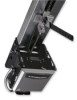
OWNER'S MANUAL MODEL T SOLID STATE INDUSTRIAL DUTY DOOR OPERATOR LOGIC LCONTROL FACTORY SET C2 Wiring See pages 13 & 14 for other wiring configurations 2 YEAR WARRANTY Serial # (located on electrical box cover) Installation Date Wiring Type NOT FOR RESIDENTIAL USE 41B6 LISTED DOOR OPERATOR - LiftMaster T | T LOGIC VERSION 1 Manual - Page 2
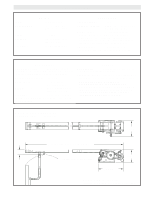
14 for optional control settings and operating modes. LIMIT ADJUST Linear driven, fully adjustable screw type cams. Adjustable to 24 feet. MECHANICAL DRIVE REDUCTION Primary: Heavy duty (5L) V-Belt. Secondary: #41 chain/sprocket. Output: #48 chain (1/3 &1/2Hp) or #41 chain (3/4 &1Hp) OUTPUT SHAFT - LiftMaster T | T LOGIC VERSION 1 Manual - Page 3
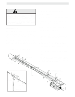
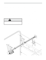
SERIOUS PERSONAL INJURY OR DEATH. CALL A PROFESSIONAL DOOR SERVICEMAN TO MOVE OR ADJUST DOOR SPRINGS OR HARDWARE. TRACK ASSEMBLY 1. Using the 3/8"-16 x 3/4 " bolts and flange hex nuts supplied, assemble the operator track by installing and tightening the track spacer brackets. Position the spacers - LiftMaster T | T LOGIC VERSION 1 Manual - Page 4
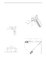
chain, or support from the floor. Now open garage door slowly, being careful not to dislodge the temporary support. Using the door as a support, place a level against the rail and shim the operator until it is horizontal. Make sure that the operator is aligned with the center line of the door. Guide - LiftMaster T | T LOGIC VERSION 1 Manual - Page 5
mounting of the support brace(s) to the powerhead, Four holes (clearance up to 3/8" bolts) are located on each side close the door and move the trolley slider to within (2") two inches of the front idler. 2. Latch the straight door arm to the fixed roll pin in the trolley carriage. Make sure the open - LiftMaster T | T LOGIC VERSION 1 Manual - Page 6
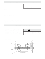
as door fully seats at the floor. WARNING TO AVOID SERIOUS PERSONAL INJURY OR DEATH FROM ELECTROCUTION, DISCONNECT ELECTRIC POWER BEFORE MANUALLY MOVING LIMIT NUTS. If other problems persist, call our toll-free number for assistance - 1-800-528-2806. OPEN Limit Switch CLOSE Limit Switch Actuator - LiftMaster T | T LOGIC VERSION 1 Manual - Page 7
STOP button. If trolley did not move in the correct direction, check for improper wiring at the control station or between operator and control station. If the operator is three phase and control station wiring is correct, exchange any two of the three incoming power leads. If electrical problems - LiftMaster T | T LOGIC VERSION 1 Manual - Page 8
Straight Door Arm Assembly Chain Curved Door Door Arm NOTICE Emergency Release Handle TO DISCONNECT DOOR FROM OPENER Emergency Disconnect Door Arm Pull emergency release handle straight down. Emergency disconnect will open. TO RECONNECT DOOR ARM TO TROLLEY Emergency Disconnect Door Arm - LiftMaster T | T LOGIC VERSION 1 Manual - Page 9
system. Solenoid Brake System Friction Pads Solenoid Release Lever Plate Assembly MAINTENANCE SCHEDULE Check at the intervals listed in the following chart. ITEM Drive Chain Sprockets Clutch Belt Fasteners Manual Disconnect Bearings & Shafts PROCEDURE Check for excessive slack. Check & adjust - LiftMaster T | T LOGIC VERSION 1 Manual - Page 10
TO REVERSE MOTOR DIRECTION Change BLUE (E16) & YELLOW (E19) wires at the PCB 10 - LiftMaster T | T LOGIC VERSION 1 Manual - Page 11
, 208-230V, 1Ø Hot 115V, 208-230V, 1Ø TB112 3 4 5 6 7 8 9 10 12 3 Remove Jumper to Install Interlock Open / Close Open Close Stop RADIO CONTROL (24V dc only) Sensing Device GND STANDARD POWER & CONTROL CONNECTION DIAGRAM Solid State Board CDO - 208-230V3Ph L1 N 208-230V, 3Ø L2 H L3 208 - LiftMaster T | T LOGIC VERSION 1 Manual - Page 12
TO REVERSE MOTOR DIRECTION Change GRAY (E10) & PURPLE (E16) wires at the PCB 12 - LiftMaster T | T LOGIC VERSION 1 Manual - Page 13
control station open button. Allow the door to run to the open limit. Set the dip switch to desired operating mode (B2, C2, D1, E2, T, TS). Set adj. mid stop 1234 OFF Set Timer to Close (NOTE: Requires P/N 1A4811 CPSII Option Board with Timer to Close Function.) Set dip switch to timer to close - LiftMaster T | T LOGIC VERSION 1 Manual - Page 14
activates timer to close. Auxiliary controls can be connected to open input to activate the timer to close. If the timer has been activated, the open button and radio control can recycle the timer. The stop button will deactivate the timer until the close button is used to close the door. (NOTE - LiftMaster T | T LOGIC VERSION 1 Manual - Page 15
NEMA MOTOR WIRING DIAGRAMS SINGLE VOLTA G E 1/3 & 1/2HP 115V ONLY Motor Purple 115V T1-Blue Grey Blue T4-Yellow T5-Black Yellow Cable T8-Red TO REVERSE MOTOR DIRECTION Change BLUE (E16) & YELLOW (E19) wires at the PCB 230V BRAKE SOLENOID (WHEN REQUIRED) Motor Grey BLACK/BLUE 115V T2-White - LiftMaster T | T LOGIC VERSION 1 Manual - Page 16
ELECTRICAL BOX - ILLUSTRATED PARTS S4 S3 S9 S5 S7 S1 S6 S2 S8 5 6 L3 L1 7 3 9 L5 L8 L6 L2 2 8 1 16 L7 4 L2 L6 2 4 - LiftMaster T | T LOGIC VERSION 1 Manual - Page 17
SWITCH ASSEMBLY KIT Descrition Qty Depress Plate 1 Spring, Depress Plate 2 Limit Switch 3 Standoff, Limit Switch 6 Screw, #4-40 x 1-3/8" Pan Head Ph 6 Screw, #6-32 x 1" Pan Hd Phil 2 Nut, Double Tinnerman 3 Locknut, #6-32 Nylon Hex 2 Lockwasher, #4 Internal Tooth 6 VARIABLE PARTS - LiftMaster T | T LOGIC VERSION 1 Manual - Page 18
ILLUSTRATED PARTS H4 H6 H8 H3 H5 TRACK DRIVE CHAIN O11 O2 O3 O9 H2 O1 O8 H7 10-10030 O10 C16 H1 O2 O4 O8 10-10011M1 O9 C3 C2 C13 C10 C14 O5 - LiftMaster T | T LOGIC VERSION 1 Manual - Page 19
DOOR DRIVE CHAIN PART # 10-5808 10-5810 10-5812 10-5814 10-5816 10-5818 10-5820 10-5820 10-5824 DESCRIPTION Track, 11' Length Track, 13' Length Track, 15' Length Track, 17' Length Track, 19' Length Track, 21' Length Track, 23' Length Track, 23' Length Track, 27'-6" Length #48 CHAIN (1/3 & 1/2 HP - LiftMaster T | T LOGIC VERSION 1 Manual - Page 20
KEYSWITCH WITH SPRING RETURN TO CENTER STANDARD 764 764 2 OR MORE Open D1 & E2 MODE ONLY Close 1 BUTTON STATION OR ANY AUXILIARY DEVICE OPEN / CLOSE 14 B2, T & TS MODE ONLY Open Open D1 & E2 MODE ONLY Close Close RESIDENTIAL RADIO CONTROLS OPEN / CLOSE 4 1 10 RADIO CONTROL (24VDC
-
 1
1 -
 2
2 -
 3
3 -
 4
4 -
 5
5 -
 6
6 -
 7
7 -
8
-
9
-
10
-
11
-
12
-
13
-
14
-
15
-
16
-
17
-
18
-
19
-
20
 |
 |

OWNER'S MANUAL
MODEL T
SOLID STATE
INDUSTRIAL DUTY DOOR OPERATOR
LOGIC CONTROL
L
C2 Wiring
FACTORY SET
See pages 13 & 14
for other wiring
configurations
NOT FOR RESIDENTIAL USE
LISTED
DOOR
OPERATOR
41B6
Serial #
(located on electrical box cover)
Installation Date
Wiring Type
2
YEAR
WARRANTY