LiftMaster TAC2C TAC2C Installation Manual
LiftMaster TAC2C Manual
 |
View all LiftMaster TAC2C manuals
Add to My Manuals
Save this manual to your list of manuals |
LiftMaster TAC2C manual content summary:
- LiftMaster TAC2C | TAC2C Installation Manual - Page 1
Installation Guide IMPORTANT: The TAC2C has a Ringer Equivalence Number (REN) of 5 with or without outlet should be wired back to its own 10 Amp minimum circuit breaker. This will prevent two problems: • Other equipment cannot introduce spikes, noise, surges, or dips into the power circuit. • The - LiftMaster TAC2C | TAC2C Installation Manual - Page 2
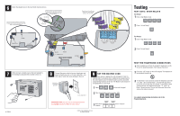
Test Relay 2 1 Enter 4 digit Master Code. RELAY 1 RELAY 2 POWER PHONE/TELCO NEW TAC2C BOARD AUTOCALL 2 Press 2 to test Relay 2. 8 Connect the power wires to the new transformer programming information refer to the Programming Guide. © 2011, The Chamberlain Group All Rights Reserved
-
 1
1 -
 2
2
 |
 |
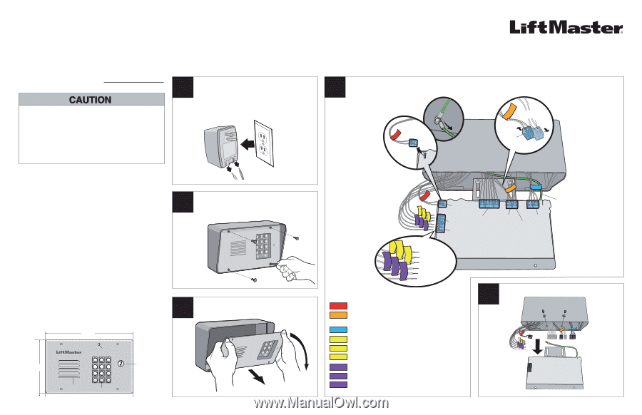
COLOR
LABEL
DESCRIPTION
POWER
16 Volt DC power input
AUTOCALL
Input for accessory device to
trigger home dialing
PHONE/TELCO
Input connection for TELCO
RELAY 2, NO
NO input for Relay 2
RELAY 2, NC
NC input for Relay 2
RELAY 2, COM
COM input for Relay 2
RELAY 1, NO
NO input for Relay 1
RELAY 1, NC
NC input for Relay 1
RELAY 1, COM
COM input for Relay 1
2
1
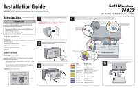
Unplug the transformer from the outlet. Disconnect the
wires from the existing transformer.
Remove the screws from the Crown Jewel faceplate
using the provided hex tool.
Slide the faceplate forward and rotate downward.
Identify the terminal blocks on the Crown Jewel board. Attach the provided labels to the
corresponding wires as shown. Once the wires are labeled, remove them from the board.
SPECIFICATIONS
Power Supply:
16 Vdc 2.5 Amp
The 110 Vac outlet must be dedicated to the unit only. This outlet
should be wired back to its own 10 Amp minimum circuit breaker.
This will prevent two problems:
•
Other equipment cannot introduce spikes, noise, surges, or dips
into the power circuit.
•
The unit’s operation will not be affected if any other equipment
develops a short circuit across the power line.
Hardware Bag
Complete with:
Hex Head Tamper Resistant Screws (4), Hex Tool (1),
and Ground Lug (1)
Faceplate with Processor Board (1)
16 Volt DC 2.5 Amp Transformer (UL Listed) (1)
Install and Programming Guide (1)
Labels (9)
CARTON INVENTORY
Introduction
4
POWER
EXTERNAL KEYPAD
(no longer available)
RELAY 1
RELAY 2
DO NOT run data wires and HIGH VOLTAGE wires in the same
conduit. The HIGH VOLTAGE wires may interfere with the data
wires and cause the unit to malfunction.
To AVOID damaging gas, power or other underground utility lines,
contact underground utility locating companies BEFORE digging.
To prevent damage to the unit:
• Use the new 16 Vdc transformer ONLY.
• Use dedicated 110 Vac outlet ONLY.
Installation Guide
TAC2C
TAC1 RETROFIT KIT FOR CROWN JEWEL SYSTEMS
Autocall
Terminal
Block
Exit Terminal Block
(no longer available)
Separate the Exit terminal block
from the Autocall terminal block by
sliding them apart as shown.
AUTOCALL
EXIT
(no longer available)
PHONE/TELCO
When the wires have
been labeled correctly,
remove the terminal
blocks from the board.
RELAY 1, COM
RELAY 1, NC
RELAY 1, NO
RELAY 2, COM
RELAY 2, NC
RELAY 2, NO
The relay wires will need to be
removed and re-wired to the terminal
block on the new board.
5
Remove the screws (2) securing the faceplate to the
housing.
Ground Wire
Remove the ground wire
that runs from the board
to the ground screw in
the existing housing.
1
2
3
4
5
6
7
8
9
*
0
#
6.22"
Keypad
Speaker
Call Button
9.72"
Dimensions:
9.72" x 6.22" (W x H)
CROWN JEWEL BOARD
IMPORTANT:
The TAC2C has a Ringer Equivalence Number (REN) of 5 with or without a TELCO line.
3
Microphone
IMPORTANT NOTE:
DO NOT use the existing transformer, the
provided
transformer MUST be used instead.