Linksys SD208 Cisco SD208 8-Port 10/100 Switch Quick Start Guide
Linksys SD208 - Cisco - 10/100 Switch Manual
 |
UPC - 745883556823
View all Linksys SD208 manuals
Add to My Manuals
Save this manual to your list of manuals |
Linksys SD208 manual content summary:
- Linksys SD208 | Cisco SD208 8-Port 10/100 Switch Quick Start Guide - Page 1
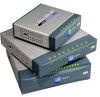
Start Guide Cisco Small Business Model SD208 8-Port 10/100 Switch Package Contents • SD208 Switch • Power Adapter • Quick Start Guide 1 Product Overview Thank you for choosing the Cisco 8-Port 10/100 Switch. The Switch provides non-blocking, wire speed switching for your 10 and 100 Mbps network - Linksys SD208 | Cisco SD208 8-Port 10/100 Switch Quick Start Guide - Page 2
a different power adapter may damage the Switch. 4 Specifications The following table lists the specifications for the SD208 10/100 Ethernet Switch. Item Model Standards Ports Cabling Type LEDs Security Feature Dimensions Specification SD208 IEEE 802.3, IEEE 802.3u 8 RJ-45 10/100 Mbps ports Cat5
-
 1
1 -
 2
2
 |
 |
Quick Start Guide
Cisco Small Business
Model SD208
8-Port 10/100 Switch
Package Contents
•
SD208 Switch
•
Power Adapter
•
Quick Start Guide
Product Overview
Thank you for choosing the Cisco 8-Port 10/100 Switch. The Switch provides
non-blocking, wire speed switching for your 10 and 100 Mbps network clients.
It's the perfect way of integrating 10Mbps Ethernet and 100Mbps Fast Ethernet
devices, too. All ports are auto speed negotiating, and have automatic MDI/MDI-
X crossover detection, so you don’t have to worry about the cable type. Each
port independently negotiates for best speed and half- or full-duplex mode, for
up to 200Mbps of bandwidth per port. Fast store-and-forward switching
prevents damaged packets from being passed on into the network.
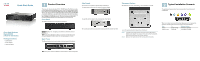
Front Panel
The LEDs are located on the front panel of the Switch.
System—
(Green) This LED lights up and remains lit when the Switch is
powered on.
1-8—
(Green) Each LED lights up when a connection is made through its
corresponding port. It flashes when the corresponding port is active.
Back Panel
The Ethernet network ports are located on the back panel of the Switch.
1-8
—These ports connect the Switch to network devices, such as computers.
1
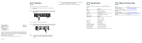
Side Panels
The power port is located on the side panel of the Switch.
The power port is where you will connect the power adapter.
The security slot is located on the opposite side of the Switch.
The security slot is where you can attach a lock to protect the Switch from theft.
Placement Options
Set the Switch on its four rubber feet, or mount the Switch on a wall.
To use the wall-mount option, follow these instructions:
S
TEP
1
The wall-mount slots are two crisscross slots on the Switch’s
bottom panel. Attach two screws to the wall, so that the Switch’s
wall-mount slots line up with the two screws.
S
TEP
2
Maneuver the Switch to insert the screws into the two slots.
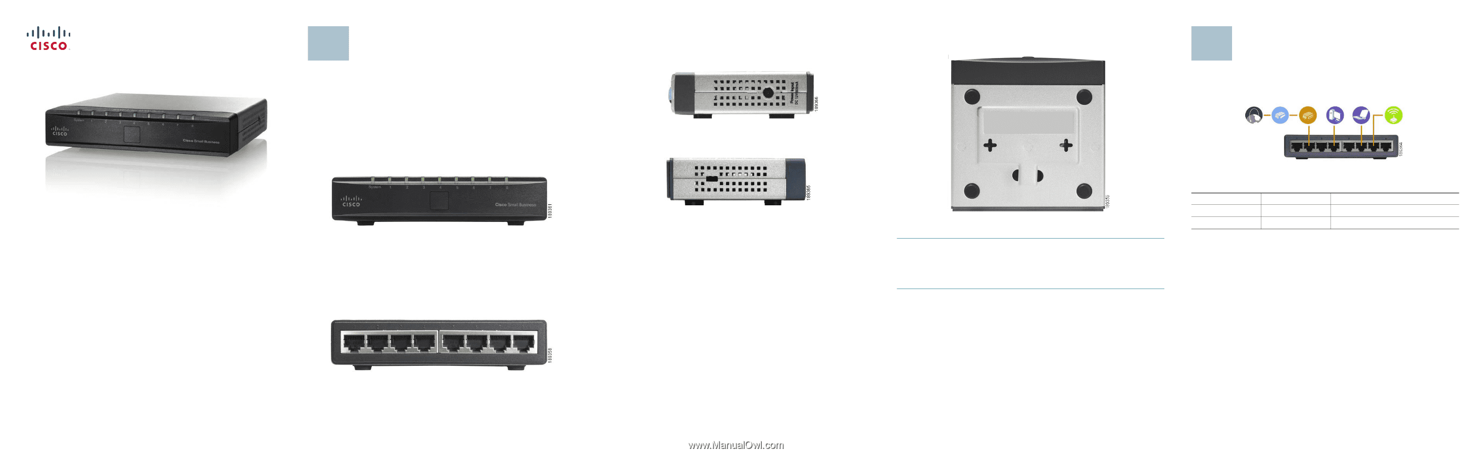
Typical Installation Scenario
The application diagram shown here is an example of a typical network
configuration.
When you connect your network devices, make sure you don’t exceed the
maximum cabling distances, which are listed in the following table:
From
To
Maximum Distance
Switch
Switch or Hub
100 meters (328 feet)
Switch or Hub
Computer
100 meters (328 feet)
2