Logitech Alert B700e Setup Guide
Logitech Alert B700e Manual
 |
View all Logitech Alert B700e manuals
Add to My Manuals
Save this manual to your list of manuals |
Logitech Alert B700e manual content summary:
- Logitech Alert B700e | Setup Guide - Page 1
with the laws in your country, state, and locality when using Logitech Alert products and services. 1 2 3 5 6 Quick-start guide LogitechAlert™ B700i PoE Security Camera System Requirements & Support Guide 7 4 Network Requirements What You'll Need Checklist Networking experience and - Logitech Alert B700e | Setup Guide - Page 2
at www.logitech.com/alert/business-support Customer Support Hotline Call 1 866-585-2877 (North America) Camera Warranty and Use Cautions Refer to System Requirements Guide. Quick-start guide LogitechAlert™ B700i PoE Security Camera System Requirements & Support Guide Troubleshooting Camera
-
 1
1 -
 2
2
 |
 |
1
Getting started with
Logitech
Alert
™
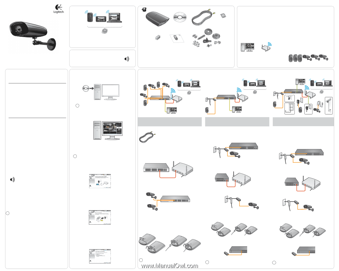
Logitech Alert B700e PoE Security Camera
1 Alert B700e PoE Camera
2 Software Install CD
3 CAT5e cable, 6m (20ft)
4
microSD
™
card adapter
5 Cable extender
6 User documentation
7
Mounting accessories
1
2
4
5
7
6
3
2) At this time, you may be asked to reboot the PC to ensure the drivers are properly
recognized by the Alert camera.
3) The Alert PoE Commander software will open.
Additional System Requirements Checklist
Ensure the PC meets these additional system requirements:
1
Basic PoE Switch to PoE Router Configuration
3
3a
3b
2
Quick-start
guide
Logitech
Alert
™
B700i PoE Security Camera
System Requirements
& Support Guide
Legal Warning
Certain uses of security camera products and audio devices, such as employee
monitoring, surreptitious viewing and recording of images and/or audio, or the
use, publication or distribution of image and/or audio recordings, are prohibited
or restricted by country, state and local laws.
Be sure to comply with the laws in your country, state, and locality when using
Logitech Alert products and services.
Installation Note
The B700e PoE security camera and software need continuous access to the Internet for web and
mobile services. This means that your network FIREWALL and/or NETWORK SECURITY settings must be
modified, if applicable, to allow the camera full access to the Internet.
We recommend working with your IT professionals at the location where you are installing this system
to help troubleshoot any camera connectivity issues [due to firewall and/or network security settings].
Web and Mobile Viewer/Commander
access anytime and anywhere
Network Requirements
What You’ll Need Checklist
Networking experience and admin rights
Windows PC that meets minimum system requirements
High-speed Internet connection for installation and setup
Router, Switch or PoE injector (works with PoE 48V IEEE
IEEE
802.3af-2003 and PoE+ 48V IEEE 802.3at-2009 high power mode
standard switch)
Ethernet cable tester
Cat5e cabling
Router
Uninterruptible Power Supply (UPS) Recommended
System Requirements
•
A router, switch, or injector is required for camera operation
•
The system requires that a DHCP server is configured on the network
•
The system requires that UPnP is enabled on the network
•
The system requires the use of the Logitech Alert™ PC Commander
software on a Windows® XP SP3, Windows® Vista, or Windows® 7
operating system
Limitations
•
Cameras cannot be assigned static IP addresses
•
Only one user name and password can be assigned to a system
•
There is a limit of up to six cameras per PC monitoring workstation
•
3rd party video monitoring, security, and recording software is not
supported
•
Remote camera access is only available through Logitech Alert™ Web
Viewer, Logitech Alert™ Mobile Viewer, and Logitech Alert™ Web and
Mobile Commander.
Windows PC meets min.
system requirements
Up to 6 camera limit
Router/PoE Router w/
high-speed Internet
connection
1
2
3
4
Test Internet connection speeds for remote viewing and e-mail and
mobile phone notifications.
Use CAT5e cable only. Validate hand-built cables using a professional
cable tester. All cables pairs (1/2, 3/6, 4/5, 7/8) must be sound.
Determine the E-mail address to be used for the Web viewing /
Commander account: username and password.
Technical Specs
•
Night vision
•
Weatherproof
•
The B700e Outdoor PoE camera is ISO 60529 IP55 rated.
•
Recommended operating temperature -30°C ~ +50°C (-22°F ~ 122°F).
CPU Speed:
Memory (GB):
Video card (min):
Remote Viewing:
Operating System
Available Ethernet port on your PoE
network:
Web & Mobile connection:
Requirement
Requirement Description
2 GHz Intel® Core™ 2 Duo or faster processor
At least 4 GB RAM
Minimum resolution of 1024 x 768. Recommend a video card
with 256 MB RAM or greater that renders HD-quality video at 15
fps
Remote viewing requires a PC or Intel®-based Mac® with Adobe®
Flash® Player 10 or later (free download). Mobile access requires a
Logitech Alert app on supported iOS, Android™, or BlackBerry®
devices.
Microsoft® Windows® Vista, Windows® XP SP3, Windows® 7
48V IEEE 802.3af-2003 and PoE+ 48V IEEE 802.3at-2009 high
power mode supported
For best performance, your cameras should be connected to a
network with 1 Mbps or greater upload speed.
To check you
upload speed go to http://www.speedtest.net or contact your ISP
1) Insert the Software Install CD and follow the instructions during the install.
The installer will check for the latest version of the software.
The B700e PoE
security camera configurations are only compatible with the latest software
version. If you are prompted to complete a software upgrade, please upgrade
until software is installed.
!
!
“Test Computer and Networking”
This utility that will automatically run will report “Powerline Network Adapter Problem: we
weren’t able to detect the Powerline Network Adapter.”
Do not click “Help me fix this.”
Click the Next >
button to continue.
Connect Cameras
PoE Switch
Router
1
INTERNET
2
3
4
B700i & B700e PoE
Security Cameras
Web and Mobile Viewer/Commander
access anytime and anywhere
Network PC work station
This basic PoE switch to router configuration uses CAT5e
cabling that allows the PoE switch to communicate to the
router and the business network. CAT5e cabling is also used
to connect each camera to the network’s PoE switch. Power is
supplied to the camera through the PoE switch.
2
By default, the cameras will search for an IP address using DHCP. Shortly after
connecting, your camera will appear in Logitech Alert Video Security Commander
software. You can now move the camera to its desired location.
!
By default, the cameras will search for an IP address using DHCP. Shortly after
connecting, your camera will appear in Logitech Alert Video Security Commander
software. You can now move the camera to its desired location.
!
By default, the cameras will search for an IP address using DHCP. Shortly after
connecting, your camera will appear in Logitech Alert Video Security Commander
software. You can now move the camera to its desired location.
!
PoE & HomePlug System (Hybrid) Configuration
Standard Switch w/ PoE Dongle Configuration
Standard Switch
Router
1
2
3
4
Network PC work station
PoE dongle/
midspan
Web and Mobile Viewer/Commander
access anytime and anywhere
B700i PoE
Camera
1
2
This Standard switch with PoE dongle configuration uses CAT5e cabling that allows the
Standard switch to communicate to the router and the business network. CAT5e cabling is
also used to connect each camera to a PoE dongle/midspan and then to the network’s
Standard switch. Power is supplied to the camera through the PoE dongle/midspan.
Example window mount
of Indoor Camera
Example mount of
Outdoor Camera
HomePlug
Power Supply
Standard Switch
Router
1
2
3
4
Network PC
work station
PoE dongle/
midspan
HomePlug
Power Supply
Logitech Alert
Indoor Camera
Logitech Alert
Outdoor Camera
Powerline Network
Adapter
B700i PoE
security
camera
Web and Mobile Viewer/Commander
access anytime and anywhere
Example drop ceiling
mount of Indoor Camera
1
2
This configuration is used for customers who already have a Logitech Alert Video
Security System. The following instructions help you connect the PoE cameras to the
existing powerline network.
This setup allows the Commander Software PC to
communicate with both the PoE cameras as well as the Alert cameras on the powerline
through the Ethernet.
(This configuration setup also assumes that the business’ network is using a standard
network switch and not a PoE switch. In this case, cameras are connected to a PoE
dongle or midspan and then the midspan is connected to the standard switch.)
4) Using CAT5e cabling, connect the PoE dongle or mid-span to an available port in the
standard network switch. (The orange line in the illustration shows the connection between the
PoE dongle/midspan and the port on the standard switch.)
3
4) Using CAT5e cabling, connect the PoE dongle or mid-span to an available port in the
standard network switch. (The orange line in the illustration shows the connection between the
PoE dongle/midspan and the port on the standard switch.)
3
2) Connect a CAT5e cable (provided with the camera) from the camera to PoE dongle or midspan.
(The orange line in the illustration shows the connection between the PoE switch and the Alert
B700i PoE camera.)
2) Connect a CAT5e cable (provided with the camera) from the camera to PoE dongle or midspan.
(The orange line in the illustration shows the connection between the PoE switch and the Alert
B700i PoE camera.)
2) Connect a CAT5e cable (provided with the camera) from a PoE port on the network to the B700e
PoE camera. (The orange line in the illustration shows the connection between the PoE switch and
the Alert B700i PoE and B700e PoE cameras.)
PoE Switch
Router
1
INTERNET
2
3
4
3) Remove the hatch from the back of the camera.
3a) Plug the supplied cable into the port.
3b) Fasten the hatch back to the camera.
Figure 1: Orange = hardwire connection to the PoE network switch from the B700e PoE cameras;
Green = hardwire connection to the PoE
switch from the Windows-based PC; Red = hardwire
connection to the router; Blue = Internet connection and remote viewing from a PC and/or an iOS,
Android™, or BlackBerry® mobile devices.
3) Remove the hatch from the back of the camera.
3a) Plug the supplied cable into the port.
3b) Fasten the hatch back to the camera.
Figure 2: Orange = hardwire connection to the standard switch and the B700e camera (via a PoE
dongle/midspan); Green = hardwire connection to the standard switch from the Windows-based PC;
Red = hardwire connection to the router; Blue = Internet connection and remote viewing from a PC
and/or an iOS, Android™, or BlackBerry® mobile devices
Figure 3: Orange = hardwire connection to the standard switch and the B700e camera (via a PoE
dongle/midspan); Green = hardwire connection to the standard switch from the Windows-based
PC and the Alert network adapter; Red = hardwire connection to the router; Blue = Internet
connection and remote viewing from a PC and/or an iOS, Android™, or BlackBerry® mobile devices
PoE Switch
B700e PoE
Security Cameras
When prompted to connect your camera:
1) Make sure a PoE switch is connected to a router.
If you have a new PoE switch for this setup,
connect the PoE switch to the router using a CAT5e cable. (The red line in the illustration shows the
connection between the router and the PoE switch.)
When prompted to connect your camera:
1) Make sure the standard network switch is connected to the router.
If you have a new standard
switch for this setup, connect the standard switch to the router using a CAT5e cable. (The red line in
the illustration shows the connection between the router and the PoE switch.)
Standard Switch
PoE dongle/
midspan
B700e PoE
Camera
Standard Switch
Router
1
INTERNET
2
3
4
PoE dongle/
midspan
B700e PoE
Camera
Standard Switch
PoE dongle/
midspan
When prompted to connect your camera:
1) Make sure the standard network switch is connected to the router.
If you have a new standard
switch for this setup, connect the standard switch to the router using a CAT5e cable. (The red line in
the illustration shows the connection between the router and the PoE switch.)
Standard Switch
Router
1
INTERNET
2
3
4
3) Remove the hatch from the back of the camera.
3a) Plug the supplied cable into the port.
3b) Fasten the hatch back to the camera.
Standard Switch
PoE dongle/
midspan
Audio monitoring and recording is included. However, depending on where the
cameras are installed, the use of recording devices may be prohibited. Be sure to
comply with the laws in your country/state/locality when using Logitech Alert
products and services.
1-year warranty
Pre-Installation Checklist
Read all instructions before beginning the installation.
A high-speed
Internet connection is required.
Ensure you are logged in as Administrator.
Make sure the PC is connected to the network.
During installation, we will test your PC’s firewall settings. If
prompted to allow the Logitech Alert camera access to the network,
you should always answer “Yes” or “Allow.”
The installation process takes several minutes and includes
powerful tools like Microsoft .NET 2.0 SP2 that is required to run the
Commander application; and UPnP, which is used to diagnose issues
with UPnP in a Windows environment.
!
Complete the First Run Wizard
The First Run Wizard automatically runs as you start Commander for the first time. It walks you
through the initial setup of system options and configuration of your cameras. Follow the
instructions to complete.
YOU MUST COMPLETE THE FIRST RUN WIZARD.
You will see screens and/or illustrations mentioning the HomePlug environment. When you see
these screens, follow these instructions
Install Software
“Plug in the Powerline Network Adapter”
There is no network adapter in the PoE setup. Ignore this screen. Click the Next > button to continue.
“Plug in Your Cameras”
Ignore the illustration because it shows the camera being connected to a power supply device.
Connect your cameras to the PoE router using Ethernet Cat-5e cables.
Click the Next > button to continue.
3
3a
3b
3
3a
3b
Standard Switch
PoE dongle/
midspan
B700e PoE
Camera
PoE dongle/
midspan
B700e PoE
Camera