Lowrance Auto-Standby button Metal H1000 Universal Interface Box Installation
Lowrance Auto-Standby button Metal Manual
 |
View all Lowrance Auto-Standby button Metal manuals
Add to My Manuals
Save this manual to your list of manuals |
Lowrance Auto-Standby button Metal manual content summary:
- Lowrance Auto-Standby button Metal | H1000 Universal Interface Box Installation - Page 1
universal interface box installation IS-2509-02 - Lowrance Auto-Standby button Metal | H1000 Universal Interface Box Installation - Page 2
energy and, if not installed and used in accordance with the instructions, m ay cause harm ful interference to radio comm unications. However qualified technician for additional help if these remedies do not correct the problem. This device meets requirements for CFR47 Part 15 of the FCC limits - Lowrance Auto-Standby button Metal | H1000 Universal Interface Box Installation - Page 3
trademark All rights reserved. No part of this manual may be reproduced or transmitted in any form or by any means including photocopying and recording, without the express written permission of B&G. Information in this - Lowrance Auto-Standby button Metal | H1000 Universal Interface Box Installation - Page 4
system connections Fastnet2 Cable Fastnet2 Cable HUB Fastnet2 Cable 12V Power Cable connections System components share data together via a common Fastnet2 databus and are supplied with bayonet connectors for ease of installation. A selection of cable lengths are available with options for - Lowrance Auto-Standby button Metal | H1000 Universal Interface Box Installation - Page 5
supported NMEA sentences (v2.40) NMEA input (received) summary NMEA Sentence APB DBT DPT GGA GLL GSA GSV HDG MWD MWV RMB RMC VHW VTG ZDA ZTG Message Description Heading/Track Controller (Autopilot) Sentence "B" Depth Below Transducer Transducer Depth and Offset Global Positioning System Fix Data - Lowrance Auto-Standby button Metal | H1000 Universal Interface Box Installation - Page 6
supported NMEA sentences (v2.40), continued B& G proprietary NMEA input (received) summary NMEA Sentence PBGTTBS PBGTLAY PBGTVMG Message Description Polar speed (knots) Distance and Time to Lay- - Lowrance Auto-Standby button Metal | H1000 Universal Interface Box Installation - Page 7
selectable NMEA The Selectable NMEA feature allows control over which sentences are received and transmitted by the h1000 Universal Interface. This gives flexibility when interfacing to other manufacturers' products such as radars and chart-plotters. Selectable NMEA allows you to filter out unwanted - Lowrance Auto-Standby button Metal | H1000 Universal Interface Box Installation - Page 8
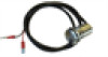
electrical connections 2 3 5 1 4 Front view of male connector pins GROMMET CABLE TIE external connections Two Fastnet² connectors are provided on the top of the unit. These connectors allow connection to the rest of the system for the supply of power and data. The table below shows pin - Lowrance Auto-Standby button Metal | H1000 Universal Interface Box Installation - Page 9
electrical connections NMEA ALARM NMEA TX+ NMEA TXNMEA SCN NMEA RXNMEA RX+ SCREEN RED + No CONN. No CONN. BLUE - UNIVERSAL 1 2 3 4 5 6 7 8 9 10 internal connections Wire the cables into the interface box as shown in the diagram opposite. m ethod To open the connector, carefully push a small flat - Lowrance Auto-Standby button Metal | H1000 Universal Interface Box Installation - Page 10
BGM014062 installation Drill 4 off holes (2.9mmØ)for No.6 x 3/4" self tapping screws 113.1mm 48mm 53mm ORIENTATION BOX BASE OUTLINE WARNING: THIS DRAWING IS NOT TO SCALE Use the Installation instructions and the template provided with the unit packaging to install the Interface Box.
-
 1
1 -
 2
2 -
 3
3 -
 4
4 -
 5
5 -
 6
6 -
 7
7 -
8
-
9
-
10
 |
 |

universal interface box
installation
IS-2509-02