Lowrance Fluid Level Sensor Installation Guide
Lowrance Fluid Level Sensor Manual
 |
View all Lowrance Fluid Level Sensor manuals
Add to My Manuals
Save this manual to your list of manuals |
Lowrance Fluid Level Sensor manual content summary:
- Lowrance Fluid Level Sensor | Installation Guide - Page 1
's negative connector. To ensure you know which connection is which, refer to the mounting instructions that came with the sending unit. Connect the Fluid Level Sensor to the network D E A B C A Fluid Level Sensor B NMEA 2000 CAN bus backbone C 12 V DC Power supply. Connect via a switch and 5 amp
-
 1
1
 |
 |

*988-10921-001*
What’s in the box
Fluid Level Sensor
Installation Guide
Tools required
Overview
Plan the installation
The sensor is designed to be the only device receiving signals
from the sending unit. If the sensor is replacing a previous gauge,
make sure you remove all the old gauge wires before you begin.
If this is a replacement, note which connection is positive before
disconnecting the old wires.
This document assumes the mounting bracket is connected to
the fluid level arm (or potentiometer) and is already installed in
the tank. The sensors wires — red (positive) and black (negative)
— will connect to the sending unit’s mounting bracket, on top of
the tank.
Use one Fluid Level Sensor for each different fluid tank. When
having 2 different tanks of similar fluids it is advisable to label
them so they can be identified in the NMEA 2000 device list in
the gauge or multi-function display.
Install the Fluid Level Sensor
Attach marine-grade crimp-on connectors to both the red lead
(+) and the black (-) lead. The Fluid Level Sensor must be the
ONLY device connected to the sender
Attach the positive red
lead to the sending unit’s
positive connector, usually
located in the center of the
mounting plate. Connect
the negative black lead to
the sending unit’s negative
connector. To ensure you
know which connection
is which, refer to the
mounting instructions that
came with the sending unit.
Wire Pliers
Drill with 22 mm (7/8” ) drill bit
Marine-grade Crimp-on wire
connectors
Zip ties for securing Fluid Level
Sensor
The Fluid Level Sensor is designed to monitor fuel, live well, oil,
fresh water, waste water (gray water), and black water tanks.
!
You should read all of the installation instructions
before proceeding. Decide where to install all components
before drilling any holes in your vessel.
The sensor is pre-configured to the US marine standard of 33.5-
240 ohm. Please refer to your operations guide for configuration
information.
!
Do NOT connect the
sensors to the NMEA
2000 network until you
have finished connecting
the red and black leads to
the sending unit. This re-
duces the risk of a spark
when working around
fuel tanks.
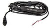
Other parts required
Fluid Level Sensor
NMEA 2000
T-Joiner
A
Red wire for positive connector in fluid level float
B
Black wire for negative connector in fluid level float
C
Fluid Level Sensor
D
NMEA 2000 connector
A
Fluid tank
B
Fluid Level Sensor
C
NMEA 2000 CAN bus
backbone
Positive
Connector
(Red)
Negative
Connector
(Black)
A
C
D
B
46 cm
(18”)
3 m
(9.8’)
Dimensions
Connect the Fluid Level Sensor to the network
A
B
C
A
Fluid Level Sensor
B
NMEA 2000 CAN bus backbone
C
12 V DC Power supply.
Connect via a switch and 5 amp fuse
D
Fluid Level Sender
E
Cable/wire leading to the Fluid Level Float in the tank
Specifications
Compatible with most sending units that are calibrated
between 33 and 240 ohm.
PGNs transmitted
59392 – ISO Acknowledgment
59904 – ISO Request
60928 – ISO Address Claim
126996 – Product Information
127505 - Fluid Level
A
B
D
E
C
86.5 mm
(3.4”)
17.1 mm
(0.67”)
9.6 mm
(0.38”)
20 mm
(0.8”)
11.5 mm
(0.45”)