Lowrance HDS-7 Gen2 Touch Installation Manual
Lowrance HDS-7 Gen2 Touch Manual
 |
View all Lowrance HDS-7 Gen2 Touch manuals
Add to My Manuals
Save this manual to your list of manuals |
Lowrance HDS-7 Gen2 Touch manual content summary:
- Lowrance HDS-7 Gen2 Touch | Installation Manual - Page 1
HDS Gen2 Touch Installation Manual ENGLISH lowrance.com - Lowrance HDS-7 Gen2 Touch | Installation Manual - Page 2
- Lowrance HDS-7 Gen2 Touch | Installation Manual - Page 3
manual. Please contact your nearest distributor if you require any further assistance. It is the owner's sole responsibility to install and use the instrument and transducers in a manner that will not cause accidents, personal injury or property damage. The user instruction manuals, user guides and - Lowrance HDS-7 Gen2 Touch | Installation Manual - Page 4
HDS-7, HDS-9, and HDS-12 Gen2 Touch for compliance could void the user's authority to operate the equipment. This equipment has installation. If this equipment does cause harmful interference to radio or television reception, which can be determined by turning the equipment off and on, the user - Lowrance HDS-7 Gen2 Touch | Installation Manual - Page 5
manual is a reference guide for installing the Lowrance HDS-7, HDS-9, and HDS-12 Gen2 Touch system. The manual does not cover basic background information about how equipment such as radars, echo sounders and AIS work. Such information is available from our web site: http://www.lowrance.com/Support - Lowrance HDS-7 Gen2 Touch | Installation Manual - Page 6
20 Transducer connection 21 Ethernet device connection 22 NMEA 2000 device connection 24 NMEA 0183 device connection 25 Video In 25 Connecting video sources 26 Software setup 26 Sonar installation settings 28 Touch Screen Calibration 28 Software upgrades 29 Dimensional drawings 29 HDS 7 Gen2 Touch - Lowrance HDS-7 Gen2 Touch | Installation Manual - Page 7
30 Accessories 30 NMEA 2000 30 Transducers 31 Ethernet cables 31 Display parts 33 Supported data 33 NMEA 2000 34 NMEA 0183 35 Specifications | 5 - Lowrance HDS-7 Gen2 Touch | Installation Manual - Page 8
the vessel with the supplied surface mount bracket, or flush mounted in to the dash. Power should be supplied at around 12V, but due to the variable nature of boat power systems, the displays are designed to operate on 10.8 V - 17 V. 6 | HDS Gen2 Touch overview | HDS Gen2 Touch Installation Manual - Lowrance HDS-7 Gen2 Touch | Installation Manual - Page 9
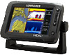
Front - controls 1 3 4 2 5 6 1 Touchscreen 2 Card reader door 3 Pages key 4 Zoom in / Zoom out key 5 Mark / Waypoint key 6 Power key HDS Gen2 Touch overview | HDS Gen2 Touch Installation Manual | 7 - Lowrance HDS-7 Gen2 Touch | Installation Manual - Page 10
& 12 connector arrangement B HDS-7 connector arrangement 1 Sonar 2 StructureScan - connects to LSS-2 HD Transducer 3 Power - also video for HDS-9 & 12, with optional adaptor 4 Ethernet - two ports on HDS-9 & 12, one on 7 5 NMEA 2000 8 | HDS Gen2 Touch overview | HDS Gen2 Touch Installation Manual - Lowrance HDS-7 Gen2 Touch | Installation Manual - Page 11
for optional Navionics or InsightHD chart data, software updates, transfer of user data and system backup. The card reader prevent possible water ingress. ¼¼ Note: The HDS-9 and 12 Displays have two card readers, the HDS-7 has one. HDS Gen2 Touch overview | HDS Gen2 Touch Installation Manual | 9 - Lowrance HDS-7 Gen2 Touch | Installation Manual - Page 12
Bracket knobs (x2) Front Bezel (attached to unit) Power cable Sun cover Fasteners - #6 x 1.5" (4x) Mounting bracket Parts Included, dependent on model 83/200 KHz transducer LSS-2 HD transducer 50/200 KHz transducer DVD - manuals 10 | Check the contents | HDS Gen2 Touch Installation Manual - Lowrance HDS-7 Gen2 Touch | Installation Manual - Page 13
Installation Mounting location Choose the mounting locations carefully before you drill or cut. The display should be mounted so that the operator can easily use the controls and clearly see the display screen to eyes, skin, and lungs. Display Installation | HDS Gen2 Touch Installation Manual | 11 - Lowrance HDS-7 Gen2 Touch | Installation Manual - Page 14
pilot holes. Screw down the bracket. 12 | Mount the display to the bracket using the knobs. Hand tighten only. The ratchet teeth in the bracket and display case ensure a positive grip and prevent the unit changing from the desired angle. Display Installation | HDS Gen2 Touch Installation Manual - Lowrance HDS-7 Gen2 Touch | Installation Manual - Page 15
") MOUNTING SCREW SIZE IS #6 TAPPING SCREW CL 110.2 mm (3.75") 99.5 mm (3.92") 95.3 mm (7.50") PRODUCSTUNOUCTOLVINEER 190.5 mm (7.50") 199.0 mm (7.83") 220.4 mm (8.68") Check dimensions before cutting 12" till it clicks in to place. Display Installation | HDS Gen2 Touch Installation Manual | 13 - Lowrance HDS-7 Gen2 Touch | Installation Manual - Page 16
5cm (3") to starboard of propeller 4 Best mounting location - undisturbed water flow 5 Planing strake - avoid mounting behind here ¼¼ Note: Reverse the distance guides (1 & 3) from propeller where engine is of counterclockwise configuration. Display Installation | HDS Gen2 Touch Installation Manual - Lowrance HDS-7 Gen2 Touch | Installation Manual - Page 17
on the other side of the mounting surface that may be damaged by drilling. Attach transducer to transom, using supplied stainless steel fasteners. Drill a 25mm (1") hole above the waterline, large enough to pass the plug through. Display Installation | HDS Gen2 Touch Installation Manual | 15 - Lowrance HDS-7 Gen2 Touch | Installation Manual - Page 18
speed. If performance does not improve with tilting, try adjusting the height of the transducer relative to the transom of the boat. If the transducer is too high it may be seeing cavitation caused by the trailing edge of the transom. 16 | Display Installation | HDS Gen2 Touch Installation Manual - Lowrance HDS-7 Gen2 Touch | Installation Manual - Page 19
off. If power is left on or turned on during the installation, fire, electrical shock, or other serious injury may occur. Be sure that the voltage of the power supply is compatible with the HDS Gen2 Touch display ! Warning: The HDS Gen2 Touch has a voltage rating of 12 V DC, it is not suited for use - Lowrance HDS-7 Gen2 Touch | Installation Manual - Page 20
modules are turned on the moment the display is powered up. ¼¼ Note: Broadband radar will be put in standby, when triggered by the accessory wake up line. For connection, simply combine all yellow wires on a common bus or to a single termination point. Wiring | HDS Gen2 Touch Installation Manual - Lowrance HDS-7 Gen2 Touch | Installation Manual - Page 21
demonstrates the power connections for a small system. 1 2 3 7 1 HDS Displays 2 HDS power cable 3 Broadband radar interface 4 SonicHub 5 12 V DC negative (-) 6 12 V DC postive (+) 7 Accessory wake up line 8 Vessel's 12 V DC supply 4 5 6 +_ 8 Wiring | HDS Gen2 Touch Installation Manual | 19 - Lowrance HDS-7 Gen2 Touch | Installation Manual - Page 22
Combo HDS Gen2 Touch displays have internal Broadband and StructureScan sonar (chart only units require an external module for sonar). Navico transducers fitted with the 7 pin blue connector can be plugged directly into the corresponding blue socket labeled 'Sonar'. The 9 pin black structure scan - Lowrance HDS-7 Gen2 Touch | Installation Manual - Page 23
interconnect high bandwidth devices such as radar, sonar, and other displays. The HDS-7 display has one ethernet port, whereas the HDS-9 and 12 displays have two. Navico ethernet ports 'lost' when used for linking multiple NEP-2 modules together. Wiring | HDS Gen2 Touch Installation Manual | 21 - Lowrance HDS-7 Gen2 Touch | Installation Manual - Page 24
this to one end of the backbone with the termination resistor at the mast head. Power the network A NMEA 2000 network requires its own 12 V DC power supply. The Lowrance NMEA 2000 power cable is pre fitted with an inline fuse holder and 3 amp fuse. 22 | Wiring | HDS Gen2 Touch Installation Manual - Lowrance HDS-7 Gen2 Touch | Installation Manual - Page 25
2 3 5 _+ 12 V DC 6 T 9 7 8 1 GPS antenna 2 HDS Display 3 Broadband radar interface 4 SonicHub 5 'Drop' cables (should not exceed 6m (20') each) 6 Power cable 7 Micro-C T junctions 8 Backbone 9 Micro-C terminator (one male, one female) 4 T 9 Wiring | HDS Gen2 Touch Installation Manual | 23 - Lowrance HDS-7 Gen2 Touch | Installation Manual - Page 26
HDS has a NMEA 0183 serial port, providing both an input and output for NMEA 0183 data. The port can be set to different baud rates, up to 115,200 baud. The NMEA0183 sentences output can be individually turned on or off. Refer to the section Supported 24 | Wiring | HDS Gen2 Touch Installation Manual - Lowrance HDS-7 Gen2 Touch | Installation Manual - Page 27
only possible to view video on the unit connected to the video source. Connecting video sources 12 V DC 1 2 3 4 1 Video input adaptor cable 2 RCA plug 3 12 V camera (3rd party) 4 HDS power/data cable ¼¼ Note: Only connect NTSC and PAL video sources Wiring | HDS Gen2 Touch Installation Manual | 25 - Lowrance HDS-7 Gen2 Touch | Installation Manual - Page 28
from transducer to the keel. Enter a negative value, e.g. B) For Depth Below Transducer: no offset required. C) For Depth Below Surface (waterline): Set the distance from transducer to the surface: Enter a positive value., e.g. 26 | A B C Software setup | HDS Gen2 Touch Installation Manual - Lowrance HDS-7 Gen2 Touch | Installation Manual - Page 29
type is used for selecting the transducer model that came with your unit. In some transducers with built-in temperature sensors, the temperature reading may be inaccurate if the wrong transducer is selected from the transducer type menu. Software setup | HDS Gen2 Touch Installation Manual | 27 - Lowrance HDS-7 Gen2 Touch | Installation Manual - Page 30
software for this unit will be available for download from the Lowrance web site; www.lowrance.com An SD card and SD reader/writer are required for this. Detailed instructions for how to install the software are provided on the update web page. 28 | Software setup | HDS Gen2 Touch Installation - Lowrance HDS-7 Gen2 Touch | Installation Manual - Page 31
mm (2.13") 178 mm (7.01") 169 mm (6.65") 287 mm (11.30") HDS 12 Gen2 Touch 328.1 mm (12.92") 12.1" 60.5 mm (2.38") 30.3 mm (1.19") 60.9 mm (2.4") 224.7 mm (8.85") 233.6 mm (9.20") 351.0 mm (13.82") 62 mm (2.44") 82.8 mm (3.26") Dimensional drawings | HDS Gen2 Touch Installation Manual | 29 - Lowrance HDS-7 Gen2 Touch | Installation Manual - Page 32
0099-97 ST-TBL TRANSOM SPEED/TEMP (NON-NMEA 2000) 000-0099-93 XT-12BL 12FT BLUE CONNECTOR TRANSDUCER EXTENSION 000-0099-94 XT-20BL 20FT BLUE CONNECTOR TRANSDUCER EXTENSION 000-10802- LSS-2 HDS SKIMMER 20 FT STRUCTURESCAN HD 001 SKIMMR XDCR LSS-2 Accessories | HDS Gen2 Touch Installation Manual - Lowrance HDS-7 Gen2 Touch | Installation Manual - Page 33
DOOR HDS-7 GEN2 TOUCH SUNCOVER HDS-9 GEN2 TOUCH SUNCOVER HDS-12 GEN2 TOUCH SUNCOVER HDS-7 GEN2 TOUCH GIMBAL BRACKET HDS-9 GEN2 TOUCH GIMBAL BRACKET HDS-12 GEN2 TOUCH GIMBAL BRACKET HDS GEN2 TOUCH FLUSH MOUNT KIT BRACKET KNOBS PAIR - NSS/GEN2T Accessories | HDS Gen2 Touch Installation Manual | 31 - Lowrance HDS-7 Gen2 Touch | Installation Manual - Page 34
Part Number 000-0127-49 000-0124-70 000-0127-50 Description HDS Power Cable HDS Connector Caps HDS Fuse & Fuse Holder 32 | Accessories | HDS Gen2 Touch Installation Manual - Lowrance HDS-7 Gen2 Touch | Installation Manual - Page 35
of Turn Attitude Magnetic Variation Engine Parameters Rapid Update Engine Parameters and Voyage Related Data AIS Addressed Safety Related Message AIS Safety Related Broadcast Message DSC Call Information Supported data | HDS Gen2 Touch Installation Manual Rx Tx 11 11 11 11 11 11 1 11 1 1 11 1 1 1 - Lowrance HDS-7 Gen2 Touch | Installation Manual - Page 36
MWV MWD Transmit MWV AIS / DSC Receive DSC DSE VDM MARPA Transmit TLL TTM ¼¼ Note: AIS sentences are not bridged to or from SimNet. 34 | Supported data | HDS Gen2 Touch Installation Manual - Lowrance HDS-7 Gen2 Touch | Installation Manual - Page 37
| HDS Gen2 Touch Installation Manual Multi Function Display Display Display resolution Display type Display brightness Touch screen Power Power supply Power consumption Technical / Environmental Housing Temperature Waterproof standard Declaration of conformity Interface Ethernet NMEA2000 Video - Lowrance HDS-7 Gen2 Touch | Installation Manual - Page 38
- Lowrance HDS-7 Gen2 Touch | Installation Manual - Page 39
- Lowrance HDS-7 Gen2 Touch | Installation Manual - Page 40
N2584 *988-10317-002*
-
 1
1 -
 2
2 -
 3
3 -
 4
4 -
 5
5 -
 6
6 -
 7
7 -
8
-
9
-
10
-
11
-
12
-
13
-
14
-
15
-
16
-
17
-
18
-
19
-
20
-
21
-
22
-
23
-
24
-
25
-
26
-
27
-
28
-
29
-
30
-
31
-
32
-
33
-
34
-
35
-
36
-
37
-
38
-
39
-
40
 |
 |

ENGLISH
HDS Gen2 Touch
Installation Manual
lowrance.com