Lowrance LMF-400 Installation and Operation Manual
Lowrance LMF-400 Manual
 |
View all Lowrance LMF-400 manuals
Add to My Manuals
Save this manual to your list of manuals |
Lowrance LMF-400 manual content summary:
- Lowrance LMF-400 | Installation and Operation Manual - Page 1
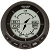
www.lowrance.com Pub. 988-0151-222 LMF-400 Multi-function Gauge Installation and Operation Instructions - Lowrance LMF-400 | Installation and Operation Manual - Page 2
the right to do so without notice. All features and specifications subject to change without notice. On the cover: LMF-400. For free owner's manuals and other information, visit our web site: www.lowrance.com Lowrance Electronics Inc. 12000 E. Skelly Dr. Tulsa, OK USA 74128-2486 Printed in USA. - Lowrance LMF-400 | Installation and Operation Manual - Page 3
3 Mounting the Gauge 3 Connecting to a NMEA 2000 Network 5 Compatibility 5 Network Backbone and Network Nodes 5 Adding a Network Node 6 Additional NMEA information 7 Understanding this manual 8 Up and Down 8 Menu 8 Pages/Enter 8 Exit 8 Menu Commands 8 Instructions = Menu Sequences - Lowrance LMF-400 | Installation and Operation Manual - Page 4
Fill 27 Economy Speed Source 27 Fuel Remaining Source 28 Reset Trip Fuel 28 Reset Seasonal 29 Customizing Pages 29 Single Analog 30 Dual Analog 31 Quad Analog 31 Single Digital 32 Dual Digital 32 Quad Digital 34 Trim Tabs 35 Fuel Manager 35 Section 4: EP Configuration & Calibration - Lowrance LMF-400 | Installation and Operation Manual - Page 5
EP Sensors 51 Calibrating EP-10 Fuel Flow 52 Fuel Flow Accuracy 52 Refill Tank 52 Reset Calibration 54 Partial Fill 54 Calibrating EP-15 Fluid Level 54 2-Point Calibration 55 3-Point Calibration 55 5-Point Calibration 56 Reset Calibration 57 Calibrating Fuel Flow in a Suzuki Engine - Lowrance LMF-400 | Installation and Operation Manual - Page 6
Notes iv - Lowrance LMF-400 | Installation and Operation Manual - Page 7
Thank you for buying the Lowrance® LMF-400! Your unit is a highquality, multi-function, digital gauge designed to work with a LowranceNET™ network. This is the NMEA 2000® networking system developed by Lowrance Electronics. Caution: Installing LowranceNET NMEA 2000 devices is significantly different - Lowrance LMF-400 | Installation and Operation Manual - Page 8
LowranceNET teams up the powerful NMEA 2000 network standard with a fast-growing, cutting-edge family of Lowrance Electronic Probe Sensors. The product line includes the EP-10 Fuel Flow, EP-15 Fluid Level, Suzuki Engine interface, EP-25 Speed, EP-35 Temp, EP-45 Pressure sensors and EP-50 Storage - Lowrance LMF-400 | Installation and Operation Manual - Page 9
in diameter. To mount the LMF-400 in the dash, first make instructions for Mounting the Unit below. 6. Connect the buzzer wires and install the buzzer. If desired, connect the dash light wires to the boat's dash light switch. 7. Connect the network cable to the NMEA 2000 network. Mounting the Gauge - Lowrance LMF-400 | Installation and Operation Manual - Page 10
wire: White wire: Piezo ground Dash light positive Blue wire: LMF-400 Housing Piezo positive Black wire: Dash light ground LMF-400 NMEA 2000 Network Cable LMF-400 with power cable wiring and NMEA 2000 Cable Connection. Connecting the LMF-400 to the buzzer (piezo), will enable the buzzer to - Lowrance LMF-400 | Installation and Operation Manual - Page 11
to the buzzer (piezo): 1. Connect the LMF-400 yellow wire to the buzzer (piezo) ground wire. 2. Attach the LMF-400 blue wire to the buzzer (piezo) downloaded free from the Lowrance web site. LowranceNET Node Kit for a NMEA 2000 network. Includes a 2 foot extension cable, T connector, 120-ohm - Lowrance LMF-400 | Installation and Operation Manual - Page 12
Lowrance or LEI device connects to new T connector. Existing network node Add T-shaped connector to add device to bus. Attach terminator at end of bus. Add a new device to a NMEA 2000 add device to bus (maintaining linear architecture) Backbone cable to rest of bus Attach terminator at end of - Lowrance LMF-400 | Installation and Operation Manual - Page 13
Operation. Additional NMEA information For more detailed information about setting up a NMEA 2000 network, refer to the "Setup and Installation of NMEA 2000 Networks, General Information" that came with your unit. If you do not have that document, it can be downloaded free from the Lowrance web site - Lowrance LMF-400 | Installation and Operation Manual - Page 14
keystrokes. Instructions for accessing a menu will look like this: 1. To access the Bus Devices list, press MENU, use the UP and DOWN keys to select SYSTEM SETUP and press ENTER. 2. Highlight BUS DEVICES and press ENTER. The Bus Devices list will appear, showing all devices on your NMEA 2000 network - Lowrance LMF-400 | Installation and Operation Manual - Page 15
this digital gauge are LMF-400 is turned on the first time, the Boat Setup menu will appear. You will not be able to proceed without completing Boat Setup. If, however, you have one or more of the following devices - Suzuki Engine Interface, EP-10 Fuel Flow, EP-15 Fluid Level, EP-45 Pressure Sensor - Lowrance LMF-400 | Installation and Operation Manual - Page 16
3 and 4 for each of the remaining tanks. 5. After all tanks on reset your engine-tank configuration to get back to Boat Setup. To reset engine-tank configuration, see enginetank configuration instructions on page 21. Basic Menu The LMF-400 or manually. Use the ENTER and EXIT keys to manually scroll - Lowrance LMF-400 | Installation and Operation Manual - Page 17
The Engine Diagnostic page displays engine performance data. It cannot be customized. Fuel Manager The Fuel Manager page has a digital readout capable of displaying nine data types, including fuel flow, fuel used and fuel remaining. GPS Position The GPS position page displays the boat's position in - Lowrance LMF-400 | Installation and Operation Manual - Page 18
four parts, each containing a small analog gauge. All four gauges can be customized to display a wide range of data, from Pitot Speed and Engine Temperature to Oil Pressure and Transmission Oil Pressure. Single Digital The Single Digital page consists of a digital data box that can be customized to - Lowrance LMF-400 | Installation and Operation Manual - Page 19
page. 4. Press ENTER, which will take you back to the main display, where the page you chose will be shown on the screen. NOTE: The LMF-400 can have up to 16 pages in the page screen rotation at one time. If you try to add a 17th page, the following message will - Lowrance LMF-400 | Installation and Operation Manual - Page 20
ways. You can scroll through pages manually by using the ENTER and EXIT keys or utilize the Page Scrolling function to have pages automatically scroll across from 2000 RPM to 1300 RPM. The pop up will expire 10 seconds after the data that exceeded the threshold stops changing. The gauge will revert - Lowrance LMF-400 | Installation and Operation Manual - Page 21
3. The Pop-Ups Setup menu will appear with five options: RPM, Engine Trim, Trim Tabs, Rudder and Stay-on Time. Select RPM and press ENTER. The RPM menu will appear with two options: Off and Set Threshold. 4. Highlight SET THRESHOLD and press ENTER. (You would select OFF to turn off the pop-up.) NOTE - Lowrance LMF-400 | Installation and Operation Manual - Page 22
The Stay-On Time command allows you to choose how long a pop-up will remain on the screen after the data stops moving. The Stay-On Time setting will Backlight The Backlight feature allows you to brighten or dim the light in the LMF-400. To adjust Backlight: 1. Press MENU, use the UP and DOWN keys to - Lowrance LMF-400 | Installation and Operation Manual - Page 23
function, all the backlight levels for components on the LowranceNet may be controlled by any of the gauges or head units in the network. If you adjust the backlight on one of the gauges level for all gauges on the LowranceNet to be synchronized with the backlight level on your LMF-400. 4. Select the - Lowrance LMF-400 | Installation and Operation Manual - Page 24
NOTE: The Reverse Video command is transmitted over the network, so all gauges will be synchronized to the same Reverse Video setting. To turn on menu (right). Audio Setup Audio Setup gives you access to the unit's audio functions. There are two options on the Audio Setup menu: Key Sounds and Alarm - Lowrance LMF-400 | Installation and Operation Manual - Page 25
Setup Menu The System Setup menu contains the following features: Engine Data, Engine Warnings, Change Units, Fuel Setup, Bus Devices, Sonar Alarms, Eng/Tank Configuration, Reset Values, NMEA Information and System Information. Speed Range and Pressure Range are included on the System Setup menu on - Lowrance LMF-400 | Installation and Operation Manual - Page 26
has been set. If Port, Center or Starboard engines are selected, the gauge will only show warnings coming from the chosen engine. (To turn off all to manage devices on the NMEA 2000 network. Accessing devices from the Bus Devices list gives you access to an EP sensor's internal menu. We will cover - Lowrance LMF-400 | Installation and Operation Manual - Page 27
on the vessel as well as fuel tank capacity. You selected your engine-tank configuration during Boat Setup. If the selected configuration is incorrect, you can return to Boat Setup by resetting the configuration from the Engine/Tank Configuration menu. To reset Eng/Tank configuration: 1. Press MENU - Lowrance LMF-400 | Installation and Operation Manual - Page 28
press ENTER. Repeat steps 6 and 7 for each remaining tank. NOTE: If you have one tank, press Reset All Values. 3. Press ENTER to reset values. You will be taken back to the main display. WARNING: Resetting values is a hard reset. All LMF-400 settings will be set back to factory defaults. Resetting - Lowrance LMF-400 | Installation and Operation Manual - Page 29
software you have in your LMF-400. To access the System Information screen: 1. Press MENU, use the UP and DOWN keys to select SYSTEM SETUP and press ENTER. 2. Highlight SYSTEM INFO and press ENTER. Press EXIT repeatedly to get back to the main display. Speed Range The Speed Range function the gauge - Lowrance LMF-400 | Installation and Operation Manual - Page 30
is 030 PSI, the unnecessary figures (31-100 PSI) will only crowd the gauge display, making it harder to read. Using the Pressure Range feature allows you Wtr Press (Engine Water Pressure), Eng Oil Press (Engine Oil Pressure), Fuel Pressure, Eng Bst Press (Engine Boost Pressure) and Trns Oil Press ( - Lowrance LMF-400 | Installation and Operation Manual - Page 31
1. Press MENU, use the UP and DOWN keys to select SYSTEM SETUP and press ENTER. 2. Highlight CHANGE UNITS and press ENTER. Select SPEED/DIST and press ENTER to open the Speed and Distance menu. 3. Select the desired option - STATUTE, NAUTICAL or SI (METRIC) - and press ENTER. The unit of measure has - Lowrance LMF-400 | Installation and Operation Manual - Page 32
Remaining Source, Reset Trip Fuel and Reset Seasonal Fuel. Refill Tank The Refill Tank command ensures the LMF-400 fuel reading is consistent with the actual amount of fuel in your tank(s). The Refill Tank command must be used with the EP-10 Fuel Flow, EP-50 Storage Device and the Suzuki NMEA 2000 - Lowrance LMF-400 | Installation and Operation Manual - Page 33
filled completely. Partial Fill must be used with the EP10 Fuel Flow, EP-50 Storage Device and the Suzuki NMEA 2000 Engine Interface. NOTE: When using the Partial Fill command, you will only be able to input an fuel amount less or equal to the fuel used figure. The unit will not allow you to input - Lowrance LMF-400 | Installation and Operation Manual - Page 34
to use a fluid level sensor for a fuel tank, you must switch the fuel remaining source to Fuel Level. If you want to use the EP-10 Fuel Flow, EP-50 Storage Device or the NMEA 2000 Suzuki Engine Interface to measure fuel remaining, select Engine/FFlow from the Fuel Remaining Source menu. To change - Lowrance LMF-400 | Installation and Operation Manual - Page 35
reset Trip Fuel. 4. Press ENTER, which will reset the trip fuel and take you back to the main display. Reset Seasonal A few sensors, like the Suzuki Engine Interface, EP-10 Fuel Flow Analog, Dual Analog, Quad Analog, Single Digital, Dual Digital, Quad Digital, Fuel Manager and Trim Tab pages. The - Lowrance LMF-400 | Installation and Operation Manual - Page 36
may be customized to display these data types: Alt Voltage, Battery Voltage, Engine Temp, Engine Water Pressure, Engine Oil Pressure, Fuel Pressure, Engine Boost Pressure, Transmission Oil Pressure, Atmospheric Pressure, Temperature, Fluid Level, Water Speed (Paddlewheel), Ground Speed (GPS), and - Lowrance LMF-400 | Installation and Operation Manual - Page 37
Dual Analog The Dual Analog page consists of two analog gauges and may be customized to show these data types: Alt Voltage, Battery Voltage, Engine Temp, Engine Water Pressure, Engine Oil Pressure, Fuel Pressure, Engine Boost Pressure, Transmission Oil Pressure, Atmospheric Pressure, Temperature, - Lowrance LMF-400 | Installation and Operation Manual - Page 38
Depth, Engine Load, Total Engine Hours, Fuel Flow, Fuel Economy, Fuel Remaining, Fuel Used, Fuel Range, Trip Fuel Use, Seasonal Fuel, Water Speed (Paddle Wheel Speed), Ground Speed (GPS) and Tachometer. To customize Single Digital page: 1. Make sure the Single Digital page has been added to the page - Lowrance LMF-400 | Installation and Operation Manual - Page 39
Depth, Engine Load, Total Engine Hours, Fuel Flow, Fuel Economy, Fuel Remaining, Fuel Used, Fuel Range, Trip Fuel Use, Seasonal Fuel, Water Speed (Paddle Wheel Speed), Ground Speed (GPS) and Tachometer. To customize the Dual Digital page: 1. Make sure the Dual Digital page has been added to the page - Lowrance LMF-400 | Installation and Operation Manual - Page 40
, Depth, Engine Load, Total Engine Hours, Fuel Flow, Fuel Economy, Fuel Remaining, Fuel Used, Fuel Range, Trip Fuel Use, Seasonal Fuel, Water Speed (Paddle Wheel Speed), Ground Speed (GPS) and Tachometer. To customize Quad Digital page: 1. Make sure the Quad Digital page has been added to the page - Lowrance LMF-400 | Installation and Operation Manual - Page 41
page (center) and Fuel Manager Page (right). Fuel Manager The Fuel Manager page has three digital data boxes stacked one on top of the other. Each digital data box can display these data types: Fuel Flow, Fuel Economy, Fuel Remaining, Fuel Used, Fuel Range, Trip Fuel Used, Seasonal Fuel, Water Speed - Lowrance LMF-400 | Installation and Operation Manual - Page 42
the Data Location menu. Repeat Steps 4-5 for the other data locations you want to customize. 2. If you chose Fuel Flow, Fuel Economy, Fuel Remaining, Fuel Used, Fuel Range, Trip Fuel Used or Seasonal Fuel, you will be taken to the Select Engine menu which will have up to three options: Port, Center - Lowrance LMF-400 | Installation and Operation Manual - Page 43
you to configure and unconfigure devices and set and reset critical values such as alarms and calibration. NOTE: The Suzuki Engine Interface, EP-35 Temperature sensor, EP-15 Fluid Level, EP-50 Storage Device and EP-10 Fuel Flow are the only sensors that can be configured through the Bus Devices list - Lowrance LMF-400 | Installation and Operation Manual - Page 44
. If you try to reconfigure a sensor when the desired configuration name (Water, Outside and Inside) is in use, a Name Already Selected message will appear. If all three temps are configured, which means there is no name configuration available, follow the first set of instructions. If the desired - Lowrance LMF-400 | Installation and Operation Manual - Page 45
Fuel Flow Configuration You can have up to three fuel flow sensors installed on your vessel, one for each engine supported by the LMF-400. The number of fuel flows two or more engines only), Fuel Warning, Unset Engine, Reset Values and Reset Calibration. After a fuel flow has been added to the - Lowrance LMF-400 | Installation and Operation Manual - Page 46
back to the Bus Devices list, where the fuel flow you unconfigured will be shown as UnCfg F Flow. To reconfigure an EP-10 Fuel Flow: You will use the Change Engine command to reconfigure a Fuel Flow. Change Engine, however, will only appear on your LMF-400 menu if you have more than one engine - Lowrance LMF-400 | Installation and Operation Manual - Page 47
UP and DOWN keys to select SYSTEM SETUP and press ENTER. 2. Highlight BUS DEVICES and press ENTER. The Bus Devices list will appear. 3. Select the fuel flow you want to reconfigure and press ENTER. Highlight CHANGE ENGINE and press ENTER. The Select Engine menu will appear with up to three options - Lowrance LMF-400 | Installation and Operation Manual - Page 48
set back to its defaults. When you Reset Values, the calibration and configuration settings of the device are set back to factory defaults. EP-15 Fluid Level Configuration The LMF-400 will support up to three tanks for each Fluid Level type which includes: Fuel, Fresh Water, Oil, Black Water, Waste - Lowrance LMF-400 | Installation and Operation Manual - Page 49
NOT be able to get a fuel range reading. Fuel Range will NOT be calculated with a fluid level sensor. It will only be calculated with an engine interface, EP-10 Fuel Flow or EP-50 Storage Device. To configure EP-15 Fluid Level for Fuel: 1. Make sure the Fuel Remaining Source has been set to Fluid - Lowrance LMF-400 | Installation and Operation Manual - Page 50
To configure EP-15 for Fresh Water: 1. Press MENU, use the UP and DOWN keys to select SYSTEM SETUP and press ENTER. 2. Highlight BUS DEVICES and press ENTER. The Bus Devices list will appear. 3. Select UNFCG F LEV and press ENTER. The following message will appear: Press Enter to configure Fluid Lev - Lowrance LMF-400 | Installation and Operation Manual - Page 51
3. Select UNFCG F LEV and press ENTER. The following message will appear: Press Enter to configure Fluid Lev Snsr. Press ENTER and the Fluid Level configuration menu will appear. 4. Choose LIVE WELL and press ENTER. The Tank Number window will appear. 5. Use the UP and DOWN keys to input the number - Lowrance LMF-400 | Installation and Operation Manual - Page 52
appear with the following options: Level Warning, Unconfigure, Reconfigure, Calibrate, Reset Cal and Reset Values. 5. Choose RECONFIGURE and press ENTER. Use the UP and DOWN level warning is used for fluid types like fuel, oil and freshwater, whereas a high level warning is best suited for black water - Lowrance LMF-400 | Installation and Operation Manual - Page 53
tank for fuel, you should choose a LOW LEVEL warning, which will warn you when the fuel level drops Reset Values Accessing the Reset Values command from the Fluid Level menu, allows you to reset the values of an individual fluid level without affecting the settings of any other sensor. To Reset - Lowrance LMF-400 | Installation and Operation Manual - Page 54
particular fluid level sensor. Executing the Reset Values command will also clear configuration and calibration settings. Suzuki Engine Interface Configuration You can have up to three Suzuki Engine Interface's installed on your vessel, one for each engine the LMF-400 supports. In a three enginetank - Lowrance LMF-400 | Installation and Operation Manual - Page 55
BUS DEVICES and press ENTER. The Fuel Flow will be listed with its new configuration setting. To reconfigure Suzuki Engine Interface (multiple engines only): of a Suzuki Engine Interface with the configuration from a different engine. Change Engine, however, will only appear on your LMF-400 menu if - Lowrance LMF-400 | Installation and Operation Manual - Page 56
back to the Bus Devices list, where the engine interface you reconfigured will be displayed with its new configuration name. Fuel Warning (Fuel Wrng) Fuel Warning allows you to set a Low level or High level alarm for each Suzuki Engine Interface on the network. A pop-up window will appear if the - Lowrance LMF-400 | Installation and Operation Manual - Page 57
the Bus Devices list. NOTE: Make sure the fuel flow has been set as the Fuel Remaining Source, otherwise, you will not be able to calibrate the fuel flow. See Fuel Remaining Source instructions on page 28. Reset Values: By accessing the Reset Values command from the Engine Interface menu, you will - Lowrance LMF-400 | Installation and Operation Manual - Page 58
or any of the digital gauge pages to the page screen rotation, then customize the selected page with Fuel Used data. To see instructions on how to Add Pages and Customize Pages, refer to the Operation Section. NOTE: Make sure the fuel flow has been set as the Fuel Remaining Source, otherwise, you - Lowrance LMF-400 | Installation and Operation Manual - Page 59
NOTE: When following the steps below, run only ONE engine - the engine connected to the fuel flow. That is the only way to accurately calculate how much fuel passed through the fuel flow. Also, make sure the fuel remaining source has been set to Eng/FFlow. 1. Fill up the tank you want to calibrate. - Lowrance LMF-400 | Installation and Operation Manual - Page 60
NOTE: It is a good idea to periodically check the calibration of a fuel flow. Reset Calibration The Reset Calibration command allows you to set fuel flow calibration back to default settings. To Reset Calibration for EP-10 Fuel Flow: 1. Press MENU, use the UP and DOWN keys to select SYSTEM SETUP and - Lowrance LMF-400 | Installation and Operation Manual - Page 61
you wish. Remember: Points that are not calibrated will not be as accurate as points that have been calibrated. For the greatest accuracy, we recommend To execute 2-Point calibration: 1. Before following the steps below, make sure your fuel tank is empty. 2. Press MENU, use the UP and DOWN keys to - Lowrance LMF-400 | Installation and Operation Manual - Page 62
wish. Remember: Points that are not calibrated will not be as accurate as points that have been calibrated. For the greatest accuracy, we Press ENTER. You will be taken back to the Levels menu. 7. Add half a tank of fuel. (If you had a 100 gallon tank, you would add 50 gallons.) 8. Select HALF LEVEL - Lowrance LMF-400 | Installation and Operation Manual - Page 63
get back to the main display. Reset Calibration The Reset Calibration command allows you to reset a fuel flow back to factory default settings. You will only need to reset calibration when you believe your fuel flow has been calibrated incorrectly. To Reset Calibration: 1. Press MENU, select SYSTEM - Lowrance LMF-400 | Installation and Operation Manual - Page 64
or any of the digital gauge pages to the page screen rotation, then customize the selected page to show Fuel Used data. To see instructions on how to Add Pages and Customize Pages, refer to the Operation Section. NOTE: Make sure the fuel flow has been set as the Fuel Remaining Source, otherwise, you - Lowrance LMF-400 | Installation and Operation Manual - Page 65
. For more information on the Refill Tank function see page 26. To calibrate a Suzuki Engine Interface: Add the Fuel Manager page or any of the digital gauge pages to the page screen rotation. Customize the page you added to show Fuel Used data. To see instructions on how to Add Pages and Customize - Lowrance LMF-400 | Installation and Operation Manual - Page 66
to calibrate. NOTE: The LMF-400 will not let you input an amount of fuel greater than the fuel used figure. Reset Fuel Calibration The Reset Calibration command allows you to reset engine interface calibration back to default settings. To reset Calibration for Suzuki Engine Interface: 1. Press MENU - Lowrance LMF-400 | Installation and Operation Manual - Page 67
4. Highlight the tank you partially filled and press ENTER. That will open the Adding Fuel window. 5. Use the UP and DOWN keys to enter the amount of fuel you added to the tank and press ENTER. You will be taken back to the main display. Calibrating EP-30 Trim Tabs Trim Tabs are - Lowrance LMF-400 | Installation and Operation Manual - Page 68
Notes 62 - Lowrance LMF-400 | Installation and Operation Manual - Page 69
rights and you may also have other rights which may vary from state to state. REMINDER: You must retain the sales slip or sales receipt proving the date of your original purchase in case warranty service is ever required. LOWRANCE ELECTRONICS 12000 E. SKELLY DRIVE, TULSA, OK 74128 (800) 324-1356 63 - Lowrance LMF-400 | Installation and Operation Manual - Page 70
if a return is necessary. Many times, customer service can resolve your problem over the phone without sending your product to the factory. call us, use the following toll-free number: 800-324-1356 8 a.m. to 5 p.m. Central Standard Time, M-F Lowrance Electronics may find it necessary to change or - Lowrance LMF-400 | Installation and Operation Manual - Page 71
order Lowrance accessories such as power cables or receive a return authorization number from Customer Service. Products shipped without a return authorization will proper testing, include a brief note with the product describing the problem. Be sure to include your name, return shipping address and - Lowrance LMF-400 | Installation and Operation Manual - Page 72
Visit our web site: Lowrance Pub. 988-0151-222 Printed in USA 121306 © Copyright 2006 All Rights Reserved Lowrance Electronics, Inc.
-
 1
1 -
 2
2 -
 3
3 -
 4
4 -
 5
5 -
 6
6 -
 7
7 -
8
-
9
-
10
-
11
-
12
-
13
-
14
-
15
-
16
-
17
-
18
-
19
-
20
-
21
-
22
-
23
-
24
-
25
-
26
-
27
-
28
-
29
-
30
-
31
-
32
-
33
-
34
-
35
-
36
-
37
-
38
-
39
-
40
-
41
-
42
-
43
-
44
-
45
-
46
-
47
-
48
-
49
-
50
-
51
-
52
-
53
-
54
-
55
-
56
-
57
-
58
-
59
-
60
-
61
-
62
-
63
-
64
-
65
-
66
-
67
-
68
-
69
-
70
-
71
-
72
 |
 |

Pub. 988-0151-222
www.lowrance.com
LMF-400
Multi-function Gauge
Installation and Operation
Instructions