Lowrance StructureScan 3D Installation Guide
Lowrance StructureScan 3D Manual
 |
View all Lowrance StructureScan 3D manuals
Add to My Manuals
Save this manual to your list of manuals |
Lowrance StructureScan 3D manual content summary:
- Lowrance StructureScan 3D | Installation Guide - Page 1
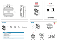
module 2 Installation screws 3 Ethernet cable, 4 m (15 ft) 4 Power cable, 2 m (6.6 ft) 5 Fuse and Fuse holder 6 StructureScan® 3D Transducer (Optional) StructureScan®3D Installation Guide Mounting For technical specifications and declarations, refer to the product website on: lowrance.com simrad - Lowrance StructureScan 3D | Installation Guide - Page 2
Software error - restart unit Sounder not operating Searching for bottom signal Operational system with bottom signal detected Wiring example 4G Radar Multi-Function Displays POWER 12V/24V 3A NET-1 NET-2 NET-3 StructureScan® 3D Module TRANSDUCER1 TRANSDUCER2 StructureScan® 3D Transducer
-
 1
1 -
 2
2
 |
 |

204 mm (8.03")
169 mm (6.63")
TRANSDUCER1
TRANSDUCER2
NET-3
NET-1
POWER
12V/24V 3A
NET-2
91 mm
(3.58")
180 mm
(7.09")
57 mm (2.24")
207 mm
(8.15")
183 mm (7.20")
Dimensions
Mounting
Parts included
DESCRIPTION
1
StructureScan® 3D module
2
Installation screws
3
Ethernet cable, 4 m (15 ft)
4
Power cable, 2 m (6.6 ft)
5
Fuse and Fuse holder
6
StructureScan® 3D Transducer (Optional)
StructureScan®3D
Installation Guide
For technical specifications and
declarations, refer to the product
website on:
*988-10970-001*
simrad-yachting.com
lowrance.com
TRANSDUCER1
TRANSDUCER2
NET-3
NET-1
POWER
NET-2
NET-3
NET-1
POWER
NET-2
NET-3
NET-1
POWER
NET-2
NET-3
NET-1
POWER
NET-2
1
2
3
4
5
6