MSI 915G COMBO-FR User Manual
MSI 915G COMBO-FR - Motherboard - ATX Manual
 |
UPC - 816909005905
View all MSI 915G COMBO-FR manuals
Add to My Manuals
Save this manual to your list of manuals |
MSI 915G COMBO-FR manual content summary:
- MSI 915G COMBO-FR | User Manual - Page 1
915P/G Combo MS-7058 (v1.X) ATX Mainboard English/French/German version G52-M7058X5 i - MSI 915G COMBO-FR | User Manual - Page 2
not installed and used in accordance with the instruction manual, may cause harmful interference to radio communications. power cord, if any, must be used in order to comply with the emission limits. VOIR LA NOTICE D'INSTALLATION AVANT DE RACCORDER AU RESEAU. Micro-Star International MS-7058 - MSI 915G COMBO-FR | User Manual - Page 3
are registered trademarks of AMD Corporation. Intel® and Pentium® are registered trademarks of Intel Corporation. PS/2 Microsoft is a registered trademark of Microsoft Corporation. Windows® 98/2000/NT/ XP are registered trademarks PCB 1.X with Intel 915P/G & Intel ICH6/ICH6R Multi-lingual version Date - MSI 915G COMBO-FR | User Manual - Page 4
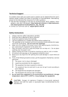
guide, BIOS updates, driver updates, and other information: http://www.msi.com.tw & http://www.msi. com.tw/program/service/faq/faq/esc_faq_list.php h Contact our technical staff at: [email protected] Safety Instructions 1. Always read the safety instructions carefully. 2. Keep this User's Manual - MSI 915G COMBO-FR | User Manual - Page 5
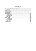
Frequency Interference Statement ii Copyright Notice ...iii Revision History ...iii Safety Instructions ...iv Technical Support ...iv English version E-1-1 1. Getting Started E-1-3 2. Hardware Setup E-2-1 3. BIOS Setup E-3-1 French version F-1-1 1. Getting Started F-1-3 2. Hardware Setup - MSI 915G COMBO-FR | User Manual - Page 6
Getting Started 915P/G Combo User's Guide English E1-1 - MSI 915G COMBO-FR | User Manual - Page 7
Carte Mère ATX 7058 ATX F1-2 - MSI 915G COMBO-FR | User Manual - Page 8
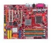
for choosing the 915P/G Combo (MS-7058) v1.X ATX mainboard. The 915P/G Combo mainboard is based on Intel® 915P/G and Intel® ICH6/ICH6R chipset for optimal system efficiency. Designed to fit the advanced Intel® Pentium Prescott LGA775 processor, the 915P/G Combo mainboard delivers a high performance - MSI 915G COMBO-FR | User Manual - Page 9
up to Pentium 4 3XX, 5XX & 7XX sequence processor or higher speed. h Supports Intel Hyper-Threading Technology. (For the latest information about CPU, please visit http://www.msi.com.tw/program/ products/mainboard/mbd/pro_mbd_cpu_support.php) Chipset h Intel® 915P/G chipset - Supports FSB 533 - MSI 915G COMBO-FR | User Manual - Page 10
integrated in Intel® ICH6/ICH6R chipset. h 8-channel audio codec CMedia CMI9880L. - Compliance with Azalia 1.X Spec. - Support Multi-Streaming function. - Support Universal Audio Jack (only Front Audio Jack). BIOS h The mainboard BIOS provides "Plug & Play" BIOS which detects the peripheral devices - MSI 915G COMBO-FR | User Manual - Page 11
B:SPDIF Out JPW1 N B FA N1 PCI_E1 PCI_E2 BIOS JCD1 CMI 9880L J AUD 1 PCI_E3 PCI 1 PCI 2 PCI 3 Intel 915P/G B AT T + SATA2 SATA4 SATA1 SATA3 IDE1 J B AT 1 JUSB1 ICH6/ ICH6R S YS FAN 1 VIA VT6410 IDE 2 IDE 3 JUSB2 JDB1 JFP2 JFP1 ATX1 915P/G Combo (MS-7058) v1.X ATX Mainboard E1-6 - MSI 915G COMBO-FR | User Manual - Page 12
Chapter 2. Hardware Setup Hardware Setup This chapter tells you how to install the CPU, memory modules, and expansion cards, as well as how to setup the jumpers on the mainboard. Also, it provides the instructions on connecting the peripheral devices, such as the mouse, keyboard, etc. While doing - MSI 915G COMBO-FR | User Manual - Page 13
MS-7058 ATX Mainboard Quick Components Guide Back Panel I/O, p.2-10 JPW1, p.2-9 CPUFAN1, p.2-9 NBFAN1, p.2-9 DDR DIMMs, p.2-7 JCI1, p.2-20 JIR1, p.2-19 FDD1, p.2-14 ATX1, p.2-9 PCI Express x16, p.2-22 PCI Express x1, p.2-22 JCD1, p.2-18 - MSI 915G COMBO-FR | User Manual - Page 14
Hardware Setup Central Processing Unit: CPU The mainboard supports Intel® Pentium 4 Prescott processor. The mainboard uses a CPU socket called LGA775. When you are installing the CPU, make sure to install the cooler to prevent overheating. If you do not have the CPU cooler, contact your dealer to - MSI 915G COMBO-FR | User Manual - Page 15
MS-7058 ATX Mainboard CPU & Cooler Installation When you are installing the CPU, make sure the CPU has a cooler attached damage of your CPU & mainboard. 1. The CPU has a plastic cap on it to protect the contact from damage. Before you install the CPU, always cover it to protect the socket pin. 2. - MSI 915G COMBO-FR | User Manual - Page 16
Setup 5. Lift the load lever up and open the load plate. 6. After confirming the CPU direction for correct mating, put down the CPU in the socket housing frame. Be sure to grasp on the edge of the CPU base. Note that the alignment keys are matched. alignment key 7. Visually inspect if the - MSI 915G COMBO-FR | User Manual - Page 17
. 12. Turn over the mainboard to confirm that the clip-ends are correctly inserted. locking switch MSI Reminds You... 1. Confirm if your CPU cooler is firmly installed before turning on your system. 2. Do not touch the CPU socket pins to avoid damaging. 3. Whenever CPU is not installed, always - MSI 915G COMBO-FR | User Manual - Page 18
for DDR1, and requires 28% less power than DDR1 chips. DDR2 truly is the future of memory, but will require some changes as the technology is not backwardly compatible and only motherboards specifically designed for DDR2 memory will be able to support these chips. DDR2 incorporates new features at - MSI 915G COMBO-FR | User Manual - Page 19
MS-7058 ATX Mainboard Memory Module Population Rules Install at least one DIMM module on the slots. Each DIMM slot supports up to a module is deeply inserted in the socket. 3. The plastic clip at each side of the DIMM slot will automatically close. Volt Notch MSI Reminds You... You can barely - MSI 915G COMBO-FR | User Manual - Page 20
is used to provide power to the CPU. JPW1 42 31 JPW1 Pin Definition PIN SIGNAL 1 GND 2 GND 3 12V 4 12V MSI Reminds You... 1. These two connectors connect to the ATX power supply and have to work together to ensure stable operation of the mainboard. 2. Power supply of 350 watts (and - MSI 915G COMBO-FR | User Manual - Page 21
MS-7058 ATX Mainboard Back Panel The back panel provides the following connectors: Mouse Parallel S/PDIF LAN L-In RS-Out Keyboard COM A VGA port (Optional) USB Ports L-Out CS-Out Mic SPDIF Out Mouse/Keyboard Connector The mainboard provides a standard PS/2® mouse/keyboard mini DIN - MSI 915G COMBO-FR | User Manual - Page 22
Data Serial Out or Transmit Data Data Terminal Ready) Ground Data Set Ready Request To Send Clear To Send Ring Indicate USB Connectors The mainboard provides an OHCI (Open Host Controller Interface) Universal Serial Bus root for attaching USB devices such as keyboard, mouse or other USBcompatible - MSI 915G COMBO-FR | User Manual - Page 23
MS-7058 ATX Mainboard LAN (RJ-45) Jack The mainboard provides 1 standard RJ-45 jack for connection to single Local Area Network (LAN). This Giga-bit LAN enables data to be transferred at 1000, 100 or 10Mbps. You can connect a network cable to it. RJ-45 LAN Jack Giga-bit LAN Pin Definition PIN - MSI 915G COMBO-FR | User Manual - Page 24
Hardware Setup Parallel Port Connector: LPT1 The mainboard provides a 25-pin female centronic connector as LPT. A parallel port is a standard printer port that supports Enhanced Parallel Port (EPP) and Extended Capabilities Parallel Port (ECP) mode. 13 1 25 14 Pin Definition PIN SIGNAL - MSI 915G COMBO-FR | User Manual - Page 25
MS-7058 ATX Mainboard Connectors The mainboard provides connectors to connect to FDD, IDE HDD, case, LAN, USB Ports and CPU/System FAN. Floppy Disk Drive Connector: FDD1 The mainboard provides a standard floppy disk drive connector that supports 360K, 720K, 1.2M, 1.44M and 2.88M floppy disk types. - MSI 915G COMBO-FR | User Manual - Page 26
The mainboard has one 32-bit Ultra DMA 66/100 IDE controller integrated in ICH6/ICH6R, which supports PIO in the optional VIA 6410 IDE Raid Controller, which supports RAID 0 & RAID 1, and can connect up to can also connect a Slave and a Master drive. MSI Reminds You... If you install two hard disks - MSI 915G COMBO-FR | User Manual - Page 27
MS-7058 ATX Mainboard Serial ATA/Serial ATA RAID Connectors controlled by Intel ICH6/ ICH6R: SATA1~SATA4 The SouthBridge of this mainboard is Intel ICH6/ICH6R which supports four serial ATA connectors SATA1~SATA4. SATA1~SATA4 are dual high-speed Serial ATA interface ports. Each supports ports MSI - MSI 915G COMBO-FR | User Manual - Page 28
Setup Front Panel Connectors: JFP1 & JFP2 The mainboard provides two front panel connectors for electrical connection to the front panel switches and LEDs. JFP1 is compliant with Intel® Front Panel I/O Connectivity Design Guide. JFP2 Power LED 7 1 8 2 Speaker Reset HDD Switch LED 9 1 10 - MSI 915G COMBO-FR | User Manual - Page 29
MS-7058 ATX Mainboard CD-In Connector: JCD1 The connector is for CD-ROM audio connector. R GND JCD1 L Front Panel Audio Connector: JAUD2 The JAUD2 front panel audio connector allows you to connect to the front panel audio and is compliant with Intel® Front Panel I/O Connectivity Design Guide. - MSI 915G COMBO-FR | User Manual - Page 30
setting through the BIOS setup to use the IR function. JIR1 is compliant with Intel® Front Panel I/O Connectivity Design Guide. 51 JIR1 62 JIR1 Pin Definition Pin Signal Pin 1 NC 2 3 VCC5 4 5 IRTX 6 Signal NC GND IRRX Front USB Connectors: JUSB1 & JUSB2 The mainboard - MSI 915G COMBO-FR | User Manual - Page 31
BIOS utility and clear the record. GND 2 CINTRU 1 JCI1 D-Bracket™ 2 Connector: JDB1 The mainboard comes with a JDB1 connector for you to connect to D-Bracket™ 2. D-Bracket™ 2 is a USB Bracket that supports both USB1.1 & 2.0 spec. It integrates four LEDs and allows users to identify system problem - MSI 915G COMBO-FR | User Manual - Page 32
change your motherboard's function through the use of jumpers. Clear CMOS Jumper: JBAT1 There is a CMOS RAM on board that has a power supply from Jumper ) to clear data. Follow the instructions below to clear the data: 1 JBAT1 3 1 Keep Data 3 1 Clear Data MSI Reminds You... You can clear CMOS by - MSI 915G COMBO-FR | User Manual - Page 33
GB/s over a PCI Express x16 lane for graphics controllers, while PCI Express x1 supports transfer rate of 250 MB/s. You can insert the expansion cards to meet your needs. When adding or removing expansion cards, make sure that you unplug the power supply first. PCI Express x16 slot PCI Express x1 - MSI 915G COMBO-FR | User Manual - Page 34
Hardware Setup PCI Interrupt Request Routing The IRQ, acronym of interrupt request line and pronounced I-R-Q, are hardware lines over which devices can send interrupt signals to the microprocessor. The PCI IRQ pins are typically connected to the PCI bus INT A# ~ INT D# pins as follows: PCI Slot 1 - MSI 915G COMBO-FR | User Manual - Page 35
features. MSI Reminds You... 1. The items under each BIOS category described in this chapter are under continuous update for BIOS maker as A=AMI(R); W=AWARD(R) 2nd - 5th digit refers to the model number. 6th - 7th digit refers to the customer, MS=all standard customers. V1.0BH refers to the BIOS - MSI 915G COMBO-FR | User Manual - Page 36
MS-7058 ATX Mainboard Entering Setup Power on the computer and the system will start POST (Power On Self Test) process. When First Boot Device You are allowed to select the 1st boot device without entering the BIOS setup utility by pressing . When the same message as listed above appears on - MSI 915G COMBO-FR | User Manual - Page 37
Menu The main menu displays the setup categories the BIOS supplies. You can use the arrow keys ( ↑↓ ) BIOS setup program provide optimal performance settings for all devices and the system. MSI Reminds You... The items under each BIOS category described in this chapter are under continuous update - MSI 915G COMBO-FR | User Manual - Page 38
MS-7058 ATX Mainboard The Main Menu Once you enter AMIBIOS NEW SETUP UTILITY, the Main menu to specify your settings for power management. PNP/PCI Configurations This entry appears if your system supports PnP/PCI. H/W/ Monitor This entry shows the status of your CPU, fan, warning for overall system - MSI 915G COMBO-FR | User Manual - Page 39
. Load Optimized Defaults Use this menu to load the default values set by the mainboard manufacturer specifically for optimal performance of the mainboard. BIOS Setting Password Use this menu to set the password for BIOS. Save & Exit Setup Save changes to CMOS and exit setup. Exit Without Saving - MSI 915G COMBO-FR | User Manual - Page 40
MS-7058 ATX Mainboard Advanced Chipset Features MSI Reminds You... Change these settings only if you are familiar with the chipset. Configure DRAM to PEG (PCI Express Graphic) for video purposes. The aperture is a portion of the PCI memory address range dedicated to graphics memory address space. - MSI 915G COMBO-FR | User Manual - Page 41
BIOS Setup SATA Device Configuration ATA/IDE Configuration, Configure SATA as These SATA2/4] [SATA1/3, IDE1] [IDE1] IDE AHCI RAID ATA/IDE Configuration (Enhanced) [IDE1, SATA 1/2/3/4] [IDE1, SATA 1/2/3/4] [IDE1, SATA 1/2/3/4], [SATA support RAID 0 or 1] For the setting options of Configure SATA - MSI 915G COMBO-FR | User Manual - Page 42
MS-7058 ATX Mainboard PNP/PCI Configurations This section describes configuring the PCI bus system and PnP (Plug & Play) feature. PCI, or Peripheral Component Interconnect, is a system which allows I/O devices to operate at speeds nearing the speed the CPU itself uses when communicating with its - MSI 915G COMBO-FR | User Manual - Page 43
CPU fan power connector (CPUFAN2) only and enables you to protect the CPU from possible overheating problem. If you don't connect the CPU fan to the CPU fan power the chassis is once opened. This item is available only when your mainboard has JCI1 jumper. To clear the warning message, set the field - MSI 915G COMBO-FR | User Manual - Page 44
MS-7058 ATX Mainboard Cell Menu The items in Cell Menu includes some important settings of CPU, AGP, DRAM and overclocking functions. MSI Reminds You... Change these settings only if you are familiar with the chipset. Current CPU Clock, Current DDR Memory Frequency These two items show the current - MSI 915G COMBO-FR | User Manual - Page 45
5th level of overclocking, increasing the CPU frequency by 10%. (for 915P only) 6th level of overclocking, increasing the CPU frequency by 15%. (for 915P only) MSI Reminds You... 1. Even though the Dynamic Overclocking Technology is more stable than manual overclocking, basically, it is still risky - MSI 915G COMBO-FR | User Manual - Page 46
MS-7058 ATX Mainboard with the setting of Adjust CPU FSB Frequency. However, you (for 915P only) the motherboard detects powered only when users' PC need to run huge amount of data like 3D games or the video MSI Reminds You... Even though the Dynamic Overclocking Technology is more stable than manual - MSI 915G COMBO-FR | User Manual - Page 47
BIOS Setup Adjust PCI Express Frequency (for 915P only) This item allows you to select the PCI Express frequency (in MHz). Select the number between [100]~[133] for needed frequency. Adjust CPU Voltage (V) The settings are used to adjust the CPU clock multiplier (ratio) and CPU motherboard problem, - MSI 915G COMBO-FR | User Manual - Page 48
MS-7058 ATX Mainboard Load Fail-Safe/Optimized Defaults The two options on the main menu allow users to restore all of the BIOS settings to the default Fail-Safe or Optimized values. The Optimized Defaults are the default values set by the mainboard manufacturer specifically for optimal performance - MSI 915G COMBO-FR | User Manual - Page 49
Introduction 915P/G Combo User's Guide French F1-1 - MSI 915G COMBO-FR | User Manual - Page 50
Carte Mère ATX 7058 ATX F1-2 - MSI 915G COMBO-FR | User Manual - Page 51
acheter une carte mère ATX 915P/G Combo (MS-7058) v1.X. La 915P/G Combo est basée sur un processeur Intel® 915P/G et un chipset Intel® ICH6/ICH6R procurant de hautes performances. Conçue pour les proceseurs Intel® Pentium Prescott LGA775, la 915P/G Combo apportera satisfaction tant aux particuliers - MSI 915G COMBO-FR | User Manual - Page 52
h Supports les processeurs Pentium 4 3XX, 5XX & 7XX. h Supporte la technologie Intel Hyper-Threading. (Pour connaître les dernières informations sur le CPU, veuillez visiter http://www. msi.com.tw/program/products/mainboard/mbd/pro_mbd_cpu_support.php) Chipset h Chipset Intel® 915P/G - Supporte FSB - MSI 915G COMBO-FR | User Manual - Page 53
intégré dans le chipset Intel® ICH6/ICH6R. h 8 canaux audio (codec CMedia CMI9880L). - Compatible avec l'Azalia 1.X Spec. - Supporte la fonction Multi-Streaming. - Supporte Universal Audio Jack (uniquement pour les jacks audio en façade). BIOS h La carte mère utilise un BIOS "Plug & Play" détectant - MSI 915G COMBO-FR | User Manual - Page 54
B:SPDIF Out JPW1 N B FA N1 PCI_E1 BIOS JCD1 CMI 9880L J AUD 1 PCI_E2 PCI_E3 PCI 1 PCI 2 PCI 3 Intel 915P/G B AT T + SATA2 SATA4 SATA1 SATA3 IDE1 J B AT 1 JUSB1 ICH6/ ICH6R S YS FAN 1 VIA VT6410 IDE 2 IDE 3 JUSB2 JDB1 JFP2 JFP1 ATX1 Carte Mère ATX 915P/G Combo (MS-7058) v1.X F1-6 - MSI 915G COMBO-FR | User Manual - Page 55
Matériel Ce chapitre vous donne des indications sur l'installation du CPU, des modules de mémoire, les cartes d'extension, ainsi que sur la configuration des cavaliers de la carte mčre. Vous retrouverez aussi des instructions pour la connexion de périphériques (souris, clavier ...). Lors de - MSI 915G COMBO-FR | User Manual - Page 56
Carte Mère ATX MS-7058 Guide des Composants Back Panel I/O, p.2-10 JPW1, p.2-9 CPUFAN1, p.2-9 NBFAN1, p.2-9 DDR DIMMs, p.2-7 JCI1, p.2-20 JIR1, p.2-19 FDD1, p.2-14 ATX1, p.2-9 PCI Express x16, p.2-22 PCI Express x1, p.2-22 - MSI 915G COMBO-FR | User Manual - Page 57
Installation Matériel Central Processing Unit: CPU La carte mère supporte les processeurs Intel® Pentium 4 Prescott. La carte mère utilise un socket CPU appelé LGA775. Quand vous avez installé votre CPU, assurez vous que le CPU possède un système de reffroidissement pour prévenir les risques de - MSI 915G COMBO-FR | User Manual - Page 58
Mère ATX MS-7058 Installer le système de refroidissement du CPU Quand vous installerez votre CPU, assurez vous que le CPU possède un le avant d'allumer l'ordinateur. 1.Le CPU possède un capot plastique le protégeant. Ne jamais retirer le capot avant que le CPU ne soit installé. 2. Retirer le - MSI 915G COMBO-FR | User Manual - Page 59
r è s v e r i f i c a t i o n d u C P U , appuyez dessus pour qu'il se connecte au socket. Verifiez en même temps que l'alignement est correct. alignment key 7. Regarder si le CPU est bien positionné dans le socket. Si non, retirez le CPU et installez le de nouveau. 8. Refermer le plateau. F2-5 - MSI 915G COMBO-FR | User Manual - Page 60
re ATX MS-7058 9. MSI Vous Rappelle... 1. Vérifier la connexion du ventilateur de CPU avant de démarre le PC. 2. Ne pas toucher les broches du CPU pour éviter de les endommager. 3. Si vous e^te amné ŕ retirer votre CPU, ne pas oublier de remettre la protection (capot) en plastique sur le socket - MSI 915G COMBO-FR | User Manual - Page 61
ne pouvez installer les deux types en même temps. Pour une mise à jour sur les modules de mémoires supportées, veuillez visiter http://www.msi.com.tw/program/products/mainboard/mbd/pro_mbd_trp_list.php. DIMM1~DIMM4 (de gauche à droite) DIMM1 & DIMM3 pour mémoire DDR2 DIMM2 & DIMM4 pour mémoire DDR1 - MSI 915G COMBO-FR | User Manual - Page 62
MS-7058 Règle de Population des Mémoires Il faut au moins installer un slot de mémoire pour que le système puisse fonctionner. fonctionner. Chaque slot DIMM peut supporter va se fermer automatiquement. Volt Encoche MSI Vous Rappelle... La marque dorée doit ą peine źtre visible lorsque - MSI 915G COMBO-FR | User Manual - Page 63
Installation Matériel Alimentation La carte supporte les alimentations ATX. Avant de connecter l'alimentation, connecteur d'alimentation 12V permet l'alimentation du CPU. JPW1 42 31 JPW1 Pin Definition PIN SIGNAL 1 GND 2 GND 3 12V 4 12V MSI Vous Rappelle... 1. Ces deux connecteurs - MSI 915G COMBO-FR | User Manual - Page 64
Carte Mère ATX MS-7058 Panneau Arrière Le panneau arričre procure les connecteurs suivants : Souris Parallèle S/PDIF LAN L-In RS-Out Clavier COM A VGA port (Optionnel) Ports USB L-Out CS-Out Mic SPDIF Out Connecteur Clavier/Souris La carte procure un connecteur Din standard pour souris PS - MSI 915G COMBO-FR | User Manual - Page 65
Installation Matériel Connecteur Port Série La carte mère possède un connecteur 9 broches male (port série). Le port est un port de communication 16550A qui envoie/reçcoit 16 bytes FIFOs. Vous pouvez y brancher une souris série ou n'importe quel autre appareils série. 1 2 3 4 5 PIN 1 2 3 4 6 - MSI 915G COMBO-FR | User Manual - Page 66
MS-7058 LAN (RJ-45) Jack La cartre mère possède en option un connecteur jack RJ-45 permettant de se connecter à un LAN (Local Area Network). Vous pouvez connecter un câble LAN sur ce jack. Le taux de transfert : 10/100/1000 Mbps. RJ-45 LAN Jack Giga-bit LAN existe une application audio avancée qui - MSI 915G COMBO-FR | User Manual - Page 67
Parallèle : LPT1 La carte procure un connecteur (25 broches femelle) pour LPT. Un port parallčle est un port imprimante standard supportant les modes EPP (Enhanced Prallel Port) et ECP (Extended Capabilities Parallel Port. 13 1 25 14 Pin Definition PIN SIGNAL DESCRIPTION 1 STROBE Strobe - MSI 915G COMBO-FR | User Manual - Page 68
Carte Mère ATX MS-7058 Connecteurs La carte est pourvue de connecteurs déstinés ą la connexion de FDD, IDE HDD, case, modem, LAN, USB Ports, IR module and CPU/System/Power Supply FAN. Connecteur Floppy Disk Drive : FDD1 La carte est pourvue d'un connecteur de disquette qui supporte les disques de - MSI 915G COMBO-FR | User Manual - Page 69
DMA 66/100/133 IDE intégré dans le VIA 6410 IDE Raid (otpionnel), supportant RAID 0 & RAID 1, et pouvant être connecté jusqu'à quatre matériels Ultra ATA IDE2 & IDE3 cpeuvent se voir connecté à un esclave ou u maître. MSI Vous Rappelle... Si vous installez 2 disques durs sur une mźme nappe, vous - MSI 915G COMBO-FR | User Manual - Page 70
MS-7058 onnecteurs Serial ATA/Serial ATA RAID Controllés par ICH6/ICH6R: SATA1~SATA4 Le Chipset sud de la carte mère (Intel ICH6/ICH6R) supporte quatre connecteurs serail ATA SATA1~SATA4. SATA1~SATA4 sont des ports d'interface doubles et trčs rapide. Chacun supportant serial ATA MSI Vous Rappelle - MSI 915G COMBO-FR | User Manual - Page 71
de l'interrupteur en faēade et des LEDs. JFP1 est compatible avec le guide Intel® Front Panel I/O Connectivity Design. JFP2 Power LED 7 1 8 2 Speaker Reset HDD Switch LED 9 1 10 2 Power Power Switch LED JFP1 JFP1 Pin Definition PIN SIGNAL 1 HD_LED_P 2 FP PWR/SLP 3 HD_LED_N - MSI 915G COMBO-FR | User Manual - Page 72
MS-7058 Connecteur CD-In : JCD1 Connecteur permettant le branchement audio du CD-Rom R GND JCD1 L Connecteur Front Panel Audio : JAUD2 Le connecteur audio JAUD2 front panel vous permet de connecter le front panel audio qui est coimpatible avec l'Intel® Front Panel I/O Connectivity Design Guide - MSI 915G COMBO-FR | User Manual - Page 73
permet de connecter u nmodule infra rouge. Vous devez configurer ce dernier dans le BIOS afin de pouvoir utiliser cette fonction. JIR1 est compatible avec l'Intel® Front Panel I/O Connectivity Design Guide. 51 JIR1 62 JIR1 Pin Definition Pin Signal Pin 1 NC 2 3 VCC5 4 5 IRTX 6 Signal - MSI 915G COMBO-FR | User Manual - Page 74
Carte Mère ATX MS-7058 Connecteur Chassis Intrusion Switch : JCI1 Ce connecteur est connécté BIOS et désactiver l'alerte. GND 2 CINTRU 1 JCI1 Connecteur D-Bracket™ 2 : JDB1 La carte possčde un connecteur JDB1 permettant la connexion d'un D-Bracket™ 2. Le D-Bracket™ 2 est un bracket USB qui supporte - MSI 915G COMBO-FR | User Manual - Page 75
un cavalier sur les broches 1-2 de JBAT1 afin de conserver les données du CMOS. Suivez les instructions pour procéder à l'éffacement : 1 JBAT1 3 1 Conserver les données 3 1 Effacer les données MSI Vous Rappelle... Vous pouvez effacer le CMOS en plaçant le cavalier sur les broche 23, lorsque le - MSI 915G COMBO-FR | User Manual - Page 76
MS-7058 Slots La carte mčre offre un slot PCI Express x16, deux slots PCI Express x1, et trois slots 32-bit PCI. Slots PCI Express le slot PCI Express, possčde une grnade bande passante, une technologie d'interconnexion et supporte de mettre en place (BIOS, cavalier etc.. Le sans fil MSI. PCI Slots - MSI 915G COMBO-FR | User Manual - Page 77
MSI vous rappelle.. 1. Les descriptions de cette rubrique sont soumises à des mises à jour régulieres. Ainsi ces descriptions peuvent être légèrement différentes de votre BIOS actuel. 2. Lors du démarrage, la version du BIOS MS V2.0 renvoie la version du BIOS. 040104 renvoie à la date de parution du - MSI 915G COMBO-FR | User Manual - Page 78
Carte Mère ATX MS-7058 Entrer dans le Setup Allumez votre ordinateur, le systčme lance le processus de POST (Power On Self Test). Quand le message ci-dessous cet élément. Cela ne change rien aux éléments du BIOS, le seul changement est que lors du prochain démarrage, le boot se fera ą partir de - MSI 915G COMBO-FR | User Manual - Page 79
selectionner un élément. Paramètrages par défaut Le paramètre "Optimal Defaults" du BIOS, procure des performances optimales et stable pour le système et les périphériques. MSI Vous Rappelle... Les éléments du BIOS sont mis à jour régulièrement permettant d'obtenir un système encore plus performant - MSI 915G COMBO-FR | User Manual - Page 80
choix relatifs aux périphériques intégrés. Power Management Features Utilisez ce menu afin de spécifier vos choix pour la gestion de l'energie. PNP/PCI Configurations Apparaît si votre système supporte PNP/PCI. H/W Monitor Voir les statuts des CPU, ventilateur, et alarme système. Cell_Menu Utilisez - MSI 915G COMBO-FR | User Manual - Page 81
, offrant ainsi des performances stables. Load Optimized Defaults Charge les paramètres optimum du BIOS sans affecter la stabilité du système. BIOS Setting Password Utilisez ce menu pour mettre un mot de passe BIOS. Save & Exit Setup Les modifications sont enregistrées dans le CMOS avant la sortie - MSI 915G COMBO-FR | User Manual - Page 82
MS-7058 Fonctions Avancées du Chipset MSI BIOS en fonction de la configurations du SPD. Choisir [Manual] vous permet de configurer la DRAM timings manuellement. Les options: [Manual manière dont la RAM est allouée au PEG (PCI Express Graphic). "L'aperture" est une portion de l'adresse mémoire PCI dédi - MSI 915G COMBO-FR | User Manual - Page 83
Configuration SATA Setup du BIOS ATA/IDE Configuration, Configure SATA as Ces deux éléments SATA2/4] [SATA1/3, IDE1] [IDE1] IDE AHCI RAID ATA/IDE Configuration (Enhanced) [IDE1, SATA 1/2/3/4] [IDE1, SATA 1/2/3/4] [IDE1, SATA 1/2/3/4], [SATA support RAID 0 or 1] Pour les paramètage des options - MSI 915G COMBO-FR | User Manual - Page 84
Carte Mère ATX MS-7058 Configurations PNP/PCI Cette section donne des informations sur le bus PCI et la fonction PnP (Plug & Play). PCI, ou Peripheral Component Interconnect, est un système qui permet aux matériels de fonctionner en E/S à une vitesse proche de celle du CPU utilisée pour communiquer - MSI 915G COMBO-FR | User Manual - Page 85
Fan Target Temp Select, vous pourrez alors choisir le nombre de broches de votre ventilateur de CPU. Assurez-vous que votre matériel corresponde bien au choix effectué dans le Bios. Les options : [3 PINS], [4 PINS]. Chassis Intrusion Active ou désactive le dispositif d'intrusion du boitīer. Lors - MSI 915G COMBO-FR | User Manual - Page 86
re ATX MS-7058 Cell Menu Vous pouvez dans ce menu gérer d'importantes fonctions du CPU, PCI Express, DRAM et d'overclocking. MSI vous rapelle... Ne changer ces paramètres que si vous maîtrisez bien ce chipset. Current CPU Clock, Current DDR Memory Frequency Vitesse d'horloge des CPU & DDR. Lecture - MSI 915G COMBO-FR | User Manual - Page 87
") augmentant la fréquence CPU de 5%. 4ème niveau d'overclocking, augmentant la fréquence CPU de 7%. 5ème niveau d'overclocking, augmentant la fréquence CPU de 10%. (pour 915P uniquement) 6ème niveau d'overclocking, augmentant la fréquence CPU de 15%. (pour 915P uniquement) MSI Vous Rappelle - MSI 915G COMBO-FR | User Manual - Page 88
Carte Mère ATX MS-7058 Adjust PCI Frequency Cet élément vous permet de sélectionner la fréquence PCI (en MHz). Par défaut cette valeur changera automatiquement en fonction de la fréquence du FSB CPU. Cependant vous devez ajuster la fréquence PCI désirée en utilisant les touches & key. Les - MSI 915G COMBO-FR | User Manual - Page 89
Setup du BIOS Adjust CPU Voltage (V) Ces éléments sont utilisés pour modifier le multiplicateur d'horloge CPU (ratio) et le voltage du core CPU (Vcore). , mais la stabilité n'est pas assurée. MSI Vous Rappelle... Les différentes couleurs utilisées pour CPU Voltage, DDR Voltage et NB Voltage, permet - MSI 915G COMBO-FR | User Manual - Page 90
Carte Mère ATX MS-7058 Load Fail-Safe/Optimized Defaults Les deux options du menu prinicpal permettent à l'utilisateur de restaurer les valeurs du BIOS. Les valeurs "Optimized Defaults" sont des valeurs définies par le fabricant de la carte mère offrant des performances optimales. Les valeurs "Fail- - MSI 915G COMBO-FR | User Manual - Page 91
User's Manual 915/G Combo User's Guide German G-1 - MSI 915G COMBO-FR | User Manual - Page 92
MS-7058 ATX Mainboard G-2 - MSI 915G COMBO-FR | User Manual - Page 93
User's Manual 915P/G Combo Benutzerhandbuch Vielen Dank für die Wahl des 915P/G Combo (MS-7058) v1.X ATX Mainboards. Das 915P/G Combo Mainboard basiert auf dem Intel® 915P/G und Intel® ICH6/ICH6R Chipsatz für optimale Systemleistung. Vorbereitet für den Einsatz des Intel® Pentium 4 Prescott LGA775 - MSI 915G COMBO-FR | User Manual - Page 94
MS-7058 ATX Mainboard Mainboard Specifications CPU h unterstützt Intel® Pentium 4 Prescott LGA775 Prozessoren im LGA775 Design h unterstützt bis zu Pentium 4 3XX, 5XX & 7XX Prozessoren oder höhere Geschwindigkeiten. h unterstützt Intel Hyper-Threading Technologie. (für neueste Informationen zur CPU- - MSI 915G COMBO-FR | User Manual - Page 95
Intel® ICH6/ICH6R chipset. h 8-Kanal Audio Codec CMI9880L. - entspricht Azalia 1.0 Spezifikation. - unterstützt Multi-Streaming-Funktion. - unterstützt Universal Audio Jack (Nur Front Audioanschlüsse). BIOS h Das Mainboard-BIOS unterstützt "Plug & Play". Das BIOS erkennt die integrierte Peripherie - MSI 915G COMBO-FR | User Manual - Page 96
u t M:CS-Out B:SPDIF Out JPW1 NBFAN1 PCI_E1 BIOS JCD1 CMI 9880L JAUD1 PCI_E2 PCI_E3 PCI 1 PCI 2 PCI 3 Intel 915P/G BATT + SATA2 SATA4 SATA1 SATA3 IDE1 J B AT 1 JUSB1 ICH6/ ICH6R SYSFAN1 VIA VT6410 IDE 2 IDE 3 JUSB2 JDB1 JFP2 JFP1 ATX1 915P/G Combo (MS-7058) v1.X ATX Mainboard G-6 - MSI 915G COMBO-FR | User Manual - Page 97
ATA RAID Anschlüsse (Intel ICH6R): SATA1~SATA4 Die Southbridge des Mainboards, Power Power LED Switch Power LED JFP1 2 1 10 9 JFP2 7 8 1 2 HDD Reset LED Switch Speaker 9 CD-In Anschluss: JCD1 dient zum Anschluss der CD-ROM Audio-Verbindung. 10 D-BracketTM 2 Anschluss: JDB1 Das Mainboard - MSI 915G COMBO-FR | User Manual - Page 98
MS-7058 ATX Mainboard 12 Audio-Anschluss für Gehäusefrontseite: JAUD1 Dieser Anschluss erlaubt die Verbindung eines Audio- BIOS Setup aktivieren. JIR1 entspricht dem Intel® Front Panel I/O Connectivity Design Guide. 14 Clear CMOS Steckbrücke: JBAT1 Auf dem Mainboard MSI-WLAN/ Bluetooth-Karte. G-8 - MSI 915G COMBO-FR | User Manual - Page 99
User's Manual Central Processing Unit: CPU Das Mainboard unterstützt Intel® Pentium 4 Prescott Prozessoren. Es verwendet einen CPU-Sockel LGA775. Wenn Sie eine CPU installiert haben, stellen Sie sicher, daß ein geeigneter CPU-Kühler installiert wird um eine Überhitzung der CPU zu verhindern. Bitte - MSI 915G COMBO-FR | User Manual - Page 100
MS-7058 ATX Mainboard CPU & Kühlerinstallation Wenn Sie eine CPU installieren, stellen Sie sicher, daß Sie einen geeigneten Prozessorkühler installieren um Üeberhitzungen zu vermeiden. Bitte wenden Sie sich bezüglich des CPU-Kühlers an Ihren Händler. Tragen Sie vor der Installation eines CPU-Kü - MSI 915G COMBO-FR | User Manual - Page 101
User's Manual 5. Klappen Sie den Hebel ganz auf (Pfeil nach links) und öffnen Sie die Metallverschlussklappe (Pfeil nach rechts). 6. Vergewissern Sie sich anhand der Justiermarkierungen und dem gelben Dreieck, daß die CPU in der korrekten Position ist. Setzen Sie anschließend die CPU in den Sockel - MSI 915G COMBO-FR | User Manual - Page 102
MS-7058 ATX Mainboard 9. Drücken Sie den Verschlusshebel mit leichtem Druck nach unten und arretieren Sie den Hebel unter dem Rückhaltehaken des CPU-Sockels. 10. Führen Sie den CPU-Kühler über den CPU-Sockel und positionieren Sie die Arretierungsstifte des Kühlers über die dafür vorgesehenen Lö - MSI 915G COMBO-FR | User Manual - Page 103
User's Manual Speicher Das Mainboard bietet 4 Slots für 240-polige DDR DIMM Module und unterstützt die aktualisierten unterstützten Speichermodule, besuchen Sie bitte die Homepage http://www.msi.com.tw/program/products/mainboard/mbd/pro_mbd_trp_list.php. DIMM1~DIMM4 (von Links nach Rechts) Kanal A ( - MSI 915G COMBO-FR | User Manual - Page 104
MS-7058 ATX Mainboard Einsatz der Speichermodule Installieren Sie mindestens ein Speichermodul in einem -Verschluss an den Seiten des DIMM-Steckplatzes wird sich automatisch schliessen. Volt Notch MSI Hinweis! Wenn das Speichermodul richtig installiert ist, können Sie die goldenen Pins des Speichermoduls - MSI 915G COMBO-FR | User Manual - Page 105
User's Manual BIOS Setup Beim Einschalten des Computers beginnt das System mit dem POST ( Power On Self Test)-Vorgang. Wenn die Taste können Sie das primäre Boot-Gerät wählen,ohne dazu das Setup des BIOS aufrufen zu müssen. Wenn die obige Meldung auf dem Bildschrim erscheint, drücken Sie - MSI 915G COMBO-FR | User Manual - Page 106
MS-7058 ATX Mainboard Das Hauptmenü zu ändern und die Performance Ihres Systems zu optimieren. Advanced Chipset Features Benutzen Sie dieses Menü, um die Werte der Chipsatz-Register die Einstellungen für integrierte Peripheriegeräte vorzunehmen. Power Management Features Benutzen Sie dieses Menü, um - MSI 915G COMBO-FR | User Manual - Page 107
User's Manual H/W/ Monitor Dieser Eintrag zeigt Informationen über CPU, Lüfter und Meldungen des gesamten System Status an. Cell_Menu Benutzen Sie diese Einstellungen um Änderungen von Frequenz und Voltzahl vorzunehmen. Load Fail-Safe Defaults Benutzen Sie dieses Menü, um die BIOS-Werte zu laden, - MSI 915G COMBO-FR | User Manual - Page 108
MS-7058 ATX Mainboard Advanced Chipset Features Hinweis von MSI... Verändern Sie diese Einstellungen nur, BIOS auf der Grundlage der Konfigurationen im SPD festzulegenden Felder. Die Einstellung Disabled ermöglicht den Benutzern, diese Felder selbst zu konfigurieren. Einstell Möglichkeiten: [Manual - MSI 915G COMBO-FR | User Manual - Page 109
User's Manual SATA Device Configuration SATA Devices Konfiguration Drücken Sie die Eingabetaste (Enter SATA2/4] [SATA1/3, IDE1] [IDE1] IDE AHCI RAID ATA/IDE Configuration (Enhanced) [IDE1, SATA 1/2/3/4] [IDE1, SATA 1/2/3/4] [IDE1, SATA 1/2/3/4], [SATA support RAID 0 or 1] Wählen Sie [ AHCI ] für - MSI 915G COMBO-FR | User Manual - Page 110
MS-7058 ATX Mainboard arbeiten, die der Geschwindigkeit nahe kommen, die die CPU selbst benutzt, wenn sie mit ihren eigenen speziellen IGD (internal graphic display) zuerst. (nur für 915G ) Das System initialisiert die PEG (PCI Express graphic) zuerst. Wenn keine PCI Express VGA Karte vorhanden ist - MSI 915G COMBO-FR | User Manual - Page 111
) realisiert und ermöglicht Ihnen, die CPU vor möglichen überhitzen zu schützen. Wenn Sie den CPU Lüfter nicht an den vorgegebenen Strom Stecker anschließen, empfehlen wir, diese Option im BIOS zu deaktivieren. Einstellungs Möglichkeiten: [Enabled], [Disabled]. CPU Smart Fan Target Temp Select Wenn - MSI 915G COMBO-FR | User Manual - Page 112
MS-7058 ATX Mainboard Cell Menu Diese Option enthält einige wichtige Einstellungs Optionen von CPU, AGP, DRAM und Übertaktungs Funktionen. Hinweis von MSI... Verändern Sie diese Einstellungen nur, wenn Sie mit dem Chipsatz vertraut sind. Current CPU CLOCK, Current DDR Memory Frequency Diese 2 - MSI 915G COMBO-FR | User Manual - Page 113
2. Wenn das System viermal hintereinander einen zufälligen Neustart ausführt, wird das BIOS ebenfalls auf die Standardwerte zurückgesetzt. Adjust CPU FSB Frequency Dieses Eigenschaft erlaubt Ihnen, den CPU Frontside-Bus(in MHZ) und übertaktungs Funktionen des Prozessors einzustellen, indem Sie den - MSI 915G COMBO-FR | User Manual - Page 114
MS-7058 ATX Mainboard sich dieser Wert in Abhängigkeit derEinstellung Adjust CPU FSB Frequency automatisch anpassen. Sie können den Express Dynamic OverClocking (nur bei 915P) Dynamic Overclocking Technology ist eine erhöht die PCIe-Frequenz um 15%. MSI weist Sie darauf hin... Auch wenn die Dynamic - MSI 915G COMBO-FR | User Manual - Page 115
Manual Adjust PCI Express Frequency (nur bei 915P) Diese Eigenschaft erlaubt Ihnen, die PCI Express Frequenz (in MHZ) einzustellen. Sie können zwichen [100]~[133] wählen, je nach benötigter Frequenz. Adjust CPU Voltage (V) Die Einstellungen werden benutzt, um die Spannung des CPU EMI-Problem haben,
-
 1
1 -
 2
2 -
 3
3 -
 4
4 -
 5
5 -
 6
6 -
 7
7 -
8
-
9
-
10
-
11
-
12
-
13
-
14
-
15
-
16
-
17
-
18
-
19
-
20
-
21
-
22
-
23
-
24
-
25
-
26
-
27
-
28
-
29
-
30
-
31
-
32
-
33
-
34
-
35
-
36
-
37
-
38
-
39
-
40
-
41
-
42
-
43
-
44
-
45
-
46
-
47
-
48
-
49
-
50
-
51
-
52
-
53
-
54
-
55
-
56
-
57
-
58
-
59
-
60
-
61
-
62
-
63
-
64
-
65
-
66
-
67
-
68
-
69
-
70
-
71
-
72
-
73
-
74
-
75
-
76
-
77
-
78
-
79
-
80
-
81
-
82
-
83
-
84
-
85
-
86
-
87
-
88
-
89
-
90
-
91
-
92
-
93
-
94
-
95
-
96
-
97
-
98
-
99
-
100
-
101
-
102
-
103
-
104
-
105
-
106
-
107
-
108
-
109
-
110
-
111
-
112
-
113
-
114
-
115
 |
 |

English/French/German version
G52-M7058X5
MS-7058 (v1.X) ATX Mainboard
915P/G Combo