MSI 945GCM5-F V2 User Guide
MSI 945GCM5-F V2 - Motherboard - Micro ATX Manual
 |
UPC - 816909039726
View all MSI 945GCM5-F V2 manuals
Add to My Manuals
Save this manual to your list of manuals |
MSI 945GCM5-F V2 manual content summary:
- MSI 945GCM5-F V2 | User Guide - Page 1
and, if not installed and used in accordance with the instruction manual, may cause harmful interference to radio communications. However, there 's authority to operate the equipment. Notice 2 Shielded interface cables and A.C. power cord, if any, must be used in order to comply with the emission - MSI 945GCM5-F V2 | User Guide - Page 2
All trademarks are the properties of their respective owners. AMD®, Athlon™ Athlon™XP, Thoroughbred™ and Duron™ are registered trademarks of AMD® Corporation. Intel® and Association. Revision History Revision Revision History V4.1 Release for 945GCM5 V2 series (Intel 945GC & ICH7) Date April, - MSI 945GCM5-F V2 | User Guide - Page 3
n Always read the safety instructions carefully. n Keep this User Manual for future reference. n Keep this equipment away If any of the following situations arises, get the equipment checked by a service personnel: - The power cord or plug is damaged. - Liquid has penetrated into the equipment. - - MSI 945GCM5-F V2 | User Guide - Page 4
sein de la communauté européenne. Par conséquent vous pouvez retourner localement ces matériels dans les points de collecte. MSI WEEE 2002/96/EC 13 2005 MSI MSI EC ESPAÑOL MSI como empresa comprometida con la protección del medio ambiente, recomienda: Bajo la directiva 2002/96/EC de la Uni - MSI 945GCM5-F V2 | User Guide - Page 5
mlü olacaktır. Avrupa Birliği'ne satılan MSI markalı ürünlerin kullanım süreleri bittiğinde MSI ürünlerin geri alınması isteği MAGYAR Annak érdekében, hogy környezetünket megvédjük, illetve környezetvédőként fellépve az MSI emlékezteti Önt, hogy ... Az Európai Unió („EU") 2005. augusztus 13-án hatá - MSI 945GCM5-F V2 | User Guide - Page 6
Table of Content English 1 Français 13 Deutsch 25 39 51 63 75 - MSI 945GCM5-F V2 | User Guide - Page 7
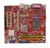
for choosing the 945GCM5 V2 series (MS-7267 v4.x) Micro-ATX mainboard. The 945GCM5 V2 series are based on Intel® 945GC & Intel® ICH7 chipsets for optimal system efficiency. Designed to fit the advanced Intel® Core2 Duo/ Pentium D/ Pentium 4 / Celeron D processor, the 945GCM5 V2 series deliver a high - MSI 945GCM5-F V2 | User Guide - Page 8
, please visit http://global.msi.com.tw/index.php?func=testreport) LAN l Supports 10/100 Mb/s Fast Ethernet by Realtek RTL 8101E l Or Supports 10/100/1000 Mb/s Fast Ethermet by Realtek RTL 8111B Audio l Chip integrated by Realtek ALC883, supports HD 5.1-channel audio-out l Or chip integrated - MSI 945GCM5-F V2 | User Guide - Page 9
Connectors l Back panel - 1 parallel port supporting SPP/EPP/ECP mode - 1 PS/2 mouse port - 1 PS/2 keyboard port - 1 COM port - 1 VGA port - 4 USB 2.0 Ports - 1 LAN jack - 3 flexible audio jacks (for ALC883 audio chip) or 6 audio jacks (for ALC888 audio chip) l On-Board Pinheaders / Connectors - 2 - MSI 945GCM5-F V2 | User Guide - Page 10
) Key boa rd Serial Port VGA Port USB Ports Mic SS-Out(optional) HARDWARE SETUP This chapter tells you how to install the CPU, memory modules, and expansion cards, as well as how to setup the jumpers on the mainboard. It also provides the instructions on connecting the peripheral devices - MSI 945GCM5-F V2 | User Guide - Page 11
to the Intel North Bridge 945GC chipset spec, this board supports CPU of FSB 800MHz at maximum by default. However, you may let your board running at FSB 1066MHz (Core 2 Duo CPUs) by overclocking and adjusting the CPU FSB frequency in the BIOS : Enter BIOS setup menu and go to [Frequency/ Voltage - MSI 945GCM5-F V2 | User Guide - Page 12
the CPU. GND GND Important: Make sure that all the connectors are connected to proper ATX power supplies to ensure stable operation of the mainboard. Power supply of 350 watts (and above) is highly recommended for system stability. Floppy Disk Drive Connector: FDD1 This connector supports 360KB - MSI 945GCM5-F V2 | User Guide - Page 13
power connectors support advantage of the CPU fan control. audio transmission. VCC SPDIF GND CD-In Connector: CD_IN1 This connector is provided for external audio input. L GND R Front Panel Audio Guide. JFP2 JFP1 87 Speaker Power LED 21 10 9 + -- + -+ Power Reset Switch Switch Power - MSI 945GCM5-F V2 | User Guide - Page 14
(Peripheral Component Interconnect) Slot The PCI slot supports LAN card, SCSI card, USB card, and other add-on cards that comply with PCI specifications. Important: When adding or removing expansion cards, make sure that you unplug the power supply first. Meanwhile, read the documentation for the - MSI 945GCM5-F V2 | User Guide - Page 15
this menu for basic system configurations, such as time, date etc. Advanced BIOS Features Use this menu to setup the items of special enhanced features. power management. PNP/PCI Configurations This entry appears if your system supports PnP/PCI. H/W Monitor This entry shows the status of your CPU, - MSI 945GCM5-F V2 | User Guide - Page 16
for system operations. Load Optimized Defaults Use this menu to load factory default settings into the BIOS for stable system performance operations. BIOS Setting Password Use this menu to set BIOS setting Password. Save & Exit Setup Save changes to CMOS and exit setup. Exit Without Saving Abandon - MSI 945GCM5-F V2 | User Guide - Page 17
frequency of Memory. Read-only. Adjust CPU FSB Frequency This item allows you to manually adjust the CPU FSB frequency. Adjust CPU Ratio This item allows you to adjust the CPU ratio. Adjusted CPU Frequency It shows the adjusted CPU frequency (FSB x Ratio). Read-only. Advance DRAM Configuration - MSI 945GCM5-F V2 | User Guide - Page 18
for long-term purpose is NOT recommended. Spread Spectrum When the motherboard's clock generator pulses, the extreme values (spikes) of the clock speed which may just cause your overclocked processor to lock up. Important: If you do not have any EMI problem, leave the setting at [Disabled] for - MSI 945GCM5-F V2 | User Guide - Page 19
carte mère des séries 945GCM5 V2(MS-7267 v4x). Les séries 945GCM5 V2 sont basées sur les VGA Port ATX1 USB ports PWRCONN1 T: LAN jack B: USB ports T:Line -I n M:Line-Out B:Mic JCI2 T:RS-Ou t (opti onal) I/O Chip M:CS-Out (optional) B:SS-Out (o ptio nal) LAN Chip PCI_E1 PCI_E2 AUDIO - MSI 945GCM5-F V2 | User Guide - Page 20
informations, veuillez visiter http://global.msi.com.tw/index.php?func=testreport) LAN: l Supporte 10/100 Mb/s Fast Ethernet par Realtek RTL 8101E l Ou supporte 10/100/1000 Fast Ethermet par Realtek RTL 8111B Audio: l Puce intégrée par Realtek ALC883, supporte 5.1 HD canal audio-sortie l Ou puce int - MSI 945GCM5-F V2 | User Guide - Page 21
l Panneau arrière : - 1 port parallèle qui supporte le mode SPP/EPP/ECP - 1 port souris PS/2 - 1 port clavier PS/2 - 1 port COM - 1 port VGA - 4 ports USB 2.0 - 1 jack LAN - 3 jacks audio flexibles (pour la carte mère qui possède la puce audio ALC883) ou 6 jacks audio (pour la carte mère qui possède - MSI 945GCM5-F V2 | User Guide - Page 22
Port VGA Port USB Ports Mic SS-Out(optional) INSTALLATION MATÉRIELLE : Ce chapitre vous donne des indications sur l'installation du CPU, des modules de mémoires, des cartes d'extension, ainsi que le positionnement des cavaliers de la carte mère. Vous retrouverez aussi des instructions pour - MSI 945GCM5-F V2 | User Guide - Page 23
supporte un CPU de FSB 800MHZ au maximum. Pourtant, vous pouvez permettre à votre carte de fonctionner à FSB 1066MHZ (Core 2 Duo CUPs) en overclockant et en ajustant la fréquence CPU FSB dans le BIOS: Entrez dans le menu d'installation du BIOS et allez à [Frequency/ Voltage Control]à[Adjust CPU FSB - MSI 945GCM5-F V2 | User Guide - Page 24
d'alimentation 12V est utilisé pour alimenter le CPU. +12V GND +12V GND Important: Assurez- la documentation du dispositif IDE pour les instructions de Configuration. Connecteurs Sérial ATA: SYSFAN2 Les connecteurs d'alimentation du ventilateur supportent le ventilateur du système avec +12V - MSI 945GCM5-F V2 | User Guide - Page 25
audio. VCC SPDIF GND Connecteur CD-Entrée: CD_IN1 Ce connecteur est utilisé pour l'entrée audio externe. L GND R Connecteur Panneau Audio en façade: JAUD1 Ce connecteur audio Guide. JFP2 JFP1 Speaker 21 10 9 Power LED + -- + -+ Power Reset Switch Switch Power dans le BIOS et désactiver - MSI 945GCM5-F V2 | User Guide - Page 26
MB/s. Slot PCI (Peripheral Component Interconnect) Le slot PCI supporte la carte LAN, la carte SCSI, la carte USB, et d'autres carte d'extension, tels que les cavaliers, les commutateurs ou la configuration du BIOS. PCI Interrupt Request Routing IRQ est l'abréviation de "interrupt request line". - MSI 945GCM5-F V2 | User Guide - Page 27
paramétrer les périphériques intégrés. Power Management Setup : Utilisez ce menu pour appliquer vos choix en ce qui concerne l'alimentation. PNP/PCI Configurations : Apparaît si votre système supporte PNP/PCI. H/W Monitor : Permet de voir les statuts du CPU, du ventilateur, et de l'alarme du syst - MSI 945GCM5-F V2 | User Guide - Page 28
l'opération du système. Load Optimized Defaults : Charge les paramètres optimaux du BIOS par défauts afin d'avoir un système plus stable. BIOS Setting Password : Utilisez ce menu pour entrer un mot de passe pour le BIOS. Save & Exit Setup : Les modifications sont enregistrées dans le CMOS avant la - MSI 945GCM5-F V2 | User Guide - Page 29
ne montre la fréquence actuelle de la Mémoire. Lecture uniquement. Adjust CPU FSB Frequency : Cette fonction vous permet d'ajuster manuellement la fréquence du CPU FSB. Adjust CPU Ratio : Cette fonction vous permet d'ajuster le ratio du CPU. Adjusted CPU Frequency : Il montre la fréquence ajustée du - MSI 945GCM5-F V2 | User Guide - Page 30
optimales. Dans le cas contraire, choisissez Enabled pour réduire les EMI. N'oubliez pas de désactiver cette fonction si vous voulez faire de l'overclocking, afin d'éviter tout problème. Important : Si vous n'avez pas de problème d'EMI, laissez l'option sur Disable, ceci vous permet d'avoir - MSI 945GCM5-F V2 | User Guide - Page 31
das 945GCM5 V2 Series (MS-7267 v4.x) Micro-ATX Mainboard gewählt haben. Das 945GCM5 V2 Series VGA Port ATX1 USB ports PWRCONN1 T: LAN jack B: USB ports T:Line -I n M:Line-Out B:Mic JCI2 T:RS-Ou t (opti onal) I/O Chip M:CS-Out (optional) B:SS-Out (o ptio nal) LAN Chip PCI_E1 PCI_E2 AUDIO - MSI 945GCM5-F V2 | User Guide - Page 32
CPU Informationen finden Sie unter http://global.msi.com.tw/index.php?func=cpuform) FSB LAN l Unterstützt 10/100 Mb/s Fast Ethernet über Realtek RTL 8101E l Unterstützt 10/100/1000 Mb/s Fast Ethermet über Realtek RTL 8111B Audio l Onboard Chip über Realtek ALC883, unterstützt 5.1- Kanal HD Audio - MSI 945GCM5-F V2 | User Guide - Page 33
/EPP/ECP - 1 PS/2 Mausanschluss - 1 PS/2 Tastaturanschluss - 1 COM Port - 1 VGA Port - 4 USB 2.0 Anschlüsse - 1 LAN Buchse - 3 flexible Audiobuchsen (für 5.1 Audio Kanal mit Realtek ALC883 Chipsatz) oder 6 Audiobuchsen (für 7.1 Audio Kanal mit Realtek ALC888 Chipsatz) l On-Board Stiftleiste / Anschl - MSI 945GCM5-F V2 | User Guide - Page 34
Mouse Parallel Port LAN Li ne-In RS-Out(optional) Li ne-Out CS-Out(optional) Key boa rd Serial Port VGA Port USB Ports Mic SS-Out(optional) HARDWARE SETUP Dieses Kapitel informiert Sie darüber, wie Sie die CPU, Speichermodule und Erweiterungskarten - MSI 945GCM5-F V2 | User Guide - Page 35
uft der 945GC Chipsatz mit einem maximalen FSB von 800MHz. Mit einem Eintrag im BIOS lässt sich der FSB erhöhen, um Intel Core 2 Duo Prozessoren mit einem FSB von 1066MHz betreiben zu können. Navigieren Sie im BIOS zu [Frequency/ Voltage Control]à[Adjust CPU FSB Frequency]. Setzen Sie hier den Wert - MSI 945GCM5-F V2 | User Guide - Page 36
GND +5V GND +5V GND PWR OK 5VSB +12V +12V +3.3V ATX 12V Stromanschluss: PWRCONN1 +12V +12V Dieser 12V Stromanschluss wird verwendet, um die CPU mit Strom GND GND zu versorgen. Wichtig: Stellen Sie die Verbindung aller drei Anschlüsse mit einem angemessenem ATX Netzteil sicher, um den stabilen - MSI 945GCM5-F V2 | User Guide - Page 37
+12V GND USB Frontanschluss: JUSB1/ JUSB2 Der Anschluss entspricht den Richtlinien des Intel® Front Panel I/O Connectivity Design Guide, und ist bestens geeignet, Hochgeschwindigkeits- USBPeripheriegeräte anzuschließen, wie z.B. USB Festplattenlaufwerke, Digitalkameras, MP3-Player, Drucker, Modems - MSI 945GCM5-F V2 | User Guide - Page 38
ügung gestellt. L GND R Audioanschluss des Frontpanels: JAUD1 Der Audio Frontanschluss ermöglicht den Anschluss von Audioein- und -ausgängen eines Panel I/O Connectivity Design Guide. JFP2 87 Speaker Power LED 21 JFP1 10 9 + -- + -+ Power Reset Switch Switch Power HDD LED LED 21 - MSI 945GCM5-F V2 | User Guide - Page 39
Steckbrücke zur CMOS- Löschung: JBAT1 1 Der Onboard CMOS Speicher (BIOS), enthält 2 Grundinformationen sowie erweite Eistellungen des 3 Mainboards. Der CMOS Speicher wird über eine Betterie mit Strom versotgt, damit die Daten nach Abschalten des PC- - MSI 945GCM5-F V2 | User Guide - Page 40
Component Interconnect) Slot Die PCI Steckplätze unterstützt LAN Karte, SCSI Karte, USB Karte und andere Zusatzkarten cards vorzunehmen, sei es an Steckbrücken („Jumpern"), Schaltern oder im BIOS. PCI Interrupt Request Routing Die IRQs (Interrupt Request Lines) sind Hardwareverbindungen - MSI 945GCM5-F V2 | User Guide - Page 41
BIOS Setup Nach dem Einschalten beginnt der Computer den POST (Power On Self Test - Selbstüberprüfung nach Anschalten). die Basiskonfiguration Ihres Systems anpassen, so z.B. Uhrzeit, Datum usw. Advanced BIOS Features Verwenden Sie diesen Menüpunkt, um AMI- eigene weitergehende Einstellungen an - MSI 945GCM5-F V2 | User Guide - Page 42
der CPU, des Lüfters und allgemeine Warnungen zum generellen Systemstatus. Frequency/Voltage Control Hier können Sie Einstellungen zu Frequenzen und Spannungen vornehmen. Load Fail-Safe Defaults In diesem Menü können Sie eine stabile, werkseitig gespeicherte Einstellung des BIOS Speichers laden - MSI 945GCM5-F V2 | User Guide - Page 43
für die CPU. Adjust CPU Ratio Hier können Sie die CPU-Taktrelation angeben. Adjusted CPU Frequency Zeigt die verstellte Frequenz der CPU (FSB x Ratio). das BIOS auf Basis der Einstellungen im SPD (Serial Presence Detect) EEPROM auf dem DRAM Modul. FSB/Memory Ratio Hier können Sie die FSB-/Speicher- - MSI 945GCM5-F V2 | User Guide - Page 44
Spannung ABGERATEN. Spread Spectrum Pulsiert der Taktgenerator des Motherboards, erzeugen die Extremwerte (Spitzen) der Pulse EMI um bestmögliche Systemstabilität und -leistung zu gewährleisten. Stellt für sie EMI ein Problem dar, wählen Sie die gewünschte Bandbreite zur Reduktion der EMI. Je größer - MSI 945GCM5-F V2 | User Guide - Page 45
945GCM5 V2 (MS-7267 v4.x) Micro-ATX 945GCM5 V2 Intel® 945GC & Intel® ICH7 Intel® Core2 Duo/ Pentium D/ Pentium 4 / Celeron D Top : mouse Bottom: keyboard CPUFAN1 DIMM1 DIMM2 Top : Parallel Port Bottom: COM Port VGA Port ATX1 USB ports PWRCONN1 T: LAN jack B: USB ports T:Line -I - MSI 945GCM5-F V2 | User Guide - Page 46
D/ Pentium 4/ Celeron D LGA 775 CPU http://global.msi.com.tw/index.php?func=cpuform) FSB l 800 / 533 МГц Чипсет l Intel® 945GC l Intel® ICH7 Память l DDR2 400/ 533/ 667 SDRAM (4 l 2 слота DDR2 DIMM (240-конт/ 1.8 http://global.msi.com.tw/index.php?func=testreport) LAN l 10/100 Мб/с Fast - MSI 945GCM5-F V2 | User Guide - Page 47
l 1 SPP/EPP/ECP - 1 PS/2 1 PS/2 1 COM порт - 1 VGA порт - 4 порта USB 2.0 - 1 LAN 3 ALC883) или 6 ALC888) l 2 USB 2.0 - 1 CD-In - 1 1 SPDIF-Out 1 Слоты l 1 PCI Express x16 слот l 1 PCI Express x1 слот l 2 PCI 3.3В/ 5В PCI шины) l Micro-ATX (24. - MSI 945GCM5-F V2 | User Guide - Page 48
Mouse Parallel Port LAN Li ne-In RS-Out(optional) Li ne-Out CS-Out(optional) Key boa rd Serial Port VGA Port USB Ports Mic SS-Out(optional) LGA 775 LGA 775 LGA 775. LGA 775. 1 2 3 4 42 - MSI 945GCM5-F V2 | User Guide - Page 49
5 6 7 8 9 10 11 BIOS Intel North Bridge 945GC FSB 800 FSB 1066МГц (Core 2 Duo CPUs FSB BIOS BIOS Setup, [Frequency/ Voltage Control]à[Adjust CPU FSB Frequency FSB до [266 Core 2 Duo 1 2 DIMM DIMM DIMM 3 43 - MSI 945GCM5-F V2 | User Guide - Page 50
Notch Vo l t DDR2 DDR DDR2 DDR2 DDR2 DIMM1. 24 ATX: ATX1 24 ATX 20 +3 . 3V -1 2V GND PS -ON # GND GND GND Res +5V +5 V +5 V GND +3.3V +3.3V GND +5V GND +5V GND PWR OK 5VSB +12V +12V +3.3V ATX +12V +12V 12В: PWRCONN1 GND GND 12 ATX 350 FDD1 360КБ, - MSI 945GCM5-F V2 | User Guide - Page 51
Serial ATA CPUFAN1, SYSFAN1 и SYSFAN2 12 12 GND Control Sensor +12V GND Sensor +12V GND USB JUSB1/ JUSB2 Intel® I/O Connectivity Design Guide USB HDD MP3 USB1+ USB1- GND (2)VCC (1)VCC N.C.(10) Key,no pin(9) USB0- GND USB0+ S/PDIF: JSPD1 S/PDIF (Sony & Philips Digital - MSI 945GCM5-F V2 | User Guide - Page 52
JFP1, JFP2 JFP1 Intel® Front Panel I/O Connectivity Design Guide. JFP2 JFP1 JCI2 BIOS. 87 Speaker Power LED 21 10 9 + -- + -+ Power Reset Switch Switch Power HDD LED LED 21 1 CINTRU 2 GND CMOS: JBAT1 CMOS CMOS 1 2 3 CMOS), 1 2 3 Keep Data 1 2 - MSI 945GCM5-F V2 | User Guide - Page 53
PCI (Peripheral Component Interconnect) PCI LAN, SCSI, USB PCI BIOS). PCI IRQ Interrupt ReQuest (line IRQ PCI PCI PCI Slot1 PCI Slot2 Order1 INT B# INT C# Order2 INT C# INT D# Order3 INT D# INT A# Order4 INT A# INT B# 47 - MSI 945GCM5-F V2 | User Guide - Page 54
BIOS POST DEL DEL SETUP RESET Ctrl>, и . Standard CMOS Features Advanced BIOS Features Integrated Peripherals Power Management Setup PNP/PCI Configurations PnP/PCI. H/W Monitor Frequency/Voltage Control Load Fail-Safe Defaults BIOS 48 - MSI 945GCM5-F V2 | User Guide - Page 55
Load Optimized Defaults BIOS BIOS Setting Password Save & Exit Setup CMOS). Exit Without Saving Frequency/Voltage Control Current CPU Frequency Current DRAM Frequency Adjust CPU FSB Frequency FSB Adjust CPU Ratio Adjusted CPU Frequency FSB x Ratio). Advance DRAM Configuration > DRAM - MSI 945GCM5-F V2 | User Guide - Page 56
CAS DRAM 2T 2.5T By SPD DRAM CAS# Latency SPD (Serial Presence Detect) EEPROM DRAM. FSB/Memory Ratio FSB/Ratio Adjusted DDR Memory Frequency DDR. Adjust PCI Frequency PCI PCI. Adjust PCIE Frequency PCI Express PCI Express. Auto Disable DIMM/PCI Frequency Enabled PCI - MSI 945GCM5-F V2 | User Guide - Page 57
简介 945GCM5 V2 系列(MS-7267 v4.x) Micro-ATX 主板。945GCM5 V2 Intel® 945GC & Intel® ICH7 Intel® Core2 Duo/ Pentium D/ Pentium 4 / Celeron D 945GCM5 V2 布局 Top : mouse Bottom: keyboard CPUFAN1 DIMM1 DIMM2 Top : Parallel Port Bottom: COM Port VGA Port ATX1 USB ports PWRCONN1 T: LAN jack B: USB - MSI 945GCM5-F V2 | User Guide - Page 58
Duo/ Pentium D/ Pentium 4/ Celeron D LGA 775 CPU http://global.msi.com.tw/index.php?func=cpuform) 前端总线 l 800 / 533 MHz 芯片组 l 北桥: Intel® 945GC 芯片组 l 南桥: Intel® ICH7 芯片组 l DDR2 400/ 533/667 (最大GB) l 2 条 DDR2 DIMM (240pin/ 1.8V http://global.msi.com.tw/index.php?func=testreport) 网络 l 由 Realtek - MSI 945GCM5-F V2 | User Guide - Page 59
接口 l 1 SPP/EPP/ECP 模式 - 1 个 PS/2 1 个 PS/2 1 个 COM 端口 - 1 个 VGA 端口 - 4 个 USB 2.0 端口 - 1 3 ALC883 6 ALC888 l 2 个 USB 2.0 针头 - 1 个 CD-In 接口 - 1 1 个 SPDIF-Out 针头 - 1 插槽 l 1 条 PCI Express x16 插槽 l 1 条 PCI Express x1 插槽 l 2 条 PCI 3.3V / 5V PCI 出厂规格 l Micro-ATX (24.5cm X 22.5 cm) 固定孔 l 6 - MSI 945GCM5-F V2 | User Guide - Page 60
LAN Li ne-In RS-Out(optional) Li ne-Out CS-Out(optional) Key boa rd Serial Port VGA Port USB Ports Mic SS-Out(optional) 硬件安装 CPU LGA775 CPU CPU CPU CPU CPU CPU CPU 安装 LGA 775 CPU LG775 CPU LG775 CPU 的表面. 1. CPU CPU CPU 2 3 4 5 CPU 盖盘。 6. 在确定 CPU CPU CPU - MSI 945GCM5-F V2 | User Guide - Page 61
8 9 10 11 12 注意: 在 BIOS 中查看 CPU CPU CPU CPU CPU Intel 北桥 945GC CPU FSB 最大 800MHZ BIOS 里调整 CPU FSB CPU FSB 运行在 1066MHZ (Core 2 Duo CPU BIOS Frequency/ Voltage Control] [Adjust CPU FSB Frequency Core 2 Duo CPU 266 安装内存 1 2 DIMM 3. DIMM Notch Vo l t DDR2 DDR DDR2 - MSI 945GCM5-F V2 | User Guide - Page 62
ON # GND GND GND Res +5V +5 V +5 V GND +3.3V +3.3V GND +5V GND +5V GND PWR OK 5VSB +12V +12V +3.3V ATX 12V PWRCONN1 此 12V CPU 供电。 +12V GND +12V GND 注意: ATX 350W FDD1 360KB, 720KB, 1.2MB, 1.44MB 或 2.88MB 软驱。 IDE 接口: IDE1 IDE IDE 设备。 注意: IDE cable select 串行 ATA 接口: SATA1 - MSI 945GCM5-F V2 | User Guide - Page 63
Sense Line-out_R JFP1, JFP2 LED。JFP1 是和 Intel® I/O JFP2 87 Speaker 21 10 9 Power LED + -- + -+ JFP1 Power Reset Switch Switch Power HDD LED LED 21 JCI2 BIOS 1 CINTRU 2 GND 清除 CMOS 跳线: JBAT1 1 2 CMOS RAM 3 CMOS RAM CMOS RAM 1 2 3 Keep Data 1 2 3 Clear - MSI 945GCM5-F V2 | User Guide - Page 64
PCI Express 插槽 PCI Express PCI Express PCI Express x 16 4.0 GB/s PCI Express x 1 支持 250 MB/s PCI PCI SCSI 卡,USB PCI BIOS 配置。 PCI IRQ PCI 的 IRQ PCI PCI Slot1 PCI Slot2 Order1 INT B# INT C# Order2 INT C# INT D# Order3 INT D# INT A# Order4 INT A# INT B# 58 - MSI 945GCM5-F V2 | User Guide - Page 65
BIOS 设置 POST DEL Press DEL to enter SETUP Setup restart Ctrl>, , 和 - MSI 945GCM5-F V2 | User Guide - Page 66
Load Fail-Safe Defaults BIOS Load Optimized Defaults BIOS Setting Password (BIOS BIOS Save & Exit Setup CMOS Exit Without Saving 60 - MSI 945GCM5-F V2 | User Guide - Page 67
DRAM Frequency (当前 DRAM Adjust CPU FSB Frequency (调整 CPU FSB CPU Disable CPU FSB 频率。 Adjust CPU Ratio (调整 CPU CPU 比率。 Adjusted CPU Frequency (调整 CPU CPU 频率(FSB x Ratio Advance DRAM Configuration > DRAM CAS# Latency CAS DRAM 2T 2.5T By SPD DRAM CAS#由 BIOS 在 DRAM SPD (Serial Presence - MSI 945GCM5-F V2 | User Guide - Page 68
Adjust PCIE Frequency (调整 PCIE PCIE Express MHZ PCIE Express Auto Disable DIMM/PCI Frequency DIMM/PCI Enabled DIMM 和 PCI EMI)。 Memory/ PCI Express Voltage (内存/ PCI Express PCI Express Spread Spectrum E M I Disabled EMI Disabled EMI Spread Spectrum EMI。 Spread Spectrum EMI Spread - MSI 945GCM5-F V2 | User Guide - Page 69
簡介 945GCM5 V2 系列(MS-7267 v4.x) Micro-ATX 945GCM5 V2 Intel® 945GC & Intel® ICH7 Intel® Core2 Duo/ Pentium D/ Pentium 4 / Celeron D 945GCM5 V2 Top : mouse Bottom: keyboard CPUFAN1 DIMM1 DIMM2 Top : Parallel Port Bottom: COM Port VGA Port ATX1 USB ports PWRCONN1 T: LAN jack B: USB - MSI 945GCM5-F V2 | User Guide - Page 70
D/ Pentium 4 / Celeron D CPU http://global.msi.com.tw/index.php?func=cpuform) 支援 FSB l 800/ 533 MHz 晶片組 l 南橋: Intel® 945GC 晶片 l 北橋: Intel® ICH7 晶片 記憶體 l DDR2 400/ 533/ 667 SDRAM 4GB) l 2 條 DDR2 DIMM slots (240pin/ 1.8V http://global.msi.com.tw/index.php?func=testreport) LAN l 由 Realtek RTL 8101E - MSI 945GCM5-F V2 | User Guide - Page 71
連接器 l SPP / EPP / ECP PS/2 PS/2 COM VGA USB2.0 LAN ALC883 ALC888 l USB2.0 CD-In S/PDIF-out 插槽 l 一個 PCI Express x16 插槽 l 一個 PCI Express x1 插槽 l 二個 PCI 3.3V / 5V PCI 尺寸 l Micro-ATX (24.5 X 22.5 公分) 裝機 l 65 - MSI 945GCM5-F V2 | User Guide - Page 72
Parallel Port LAN Li ne-In RS-Out(optional) Li ne-Out CS-Out(optional) Key boa rd Serial Port 硬體設定 VGA Port USB Ports USB Mic SS-Out(optional) 安裝 LGA775 LGA 775 LGA 775 CPU 針腳座 LGA 775 CPU 表面. Pin1 指示器 Pin1 指示器 1. CPU CPU CPU 2 3 4 5 6. 確認 CPU 66 - MSI 945GCM5-F V2 | User Guide - Page 73
7. 檢視 CPU CPU 8 9 10 11 12 BIOS 檢視 CPU CPU CPU Intel 南橋 945GC FSB 800MHz BIOS 調整 CPU FSB 1066MHz (Core 2 Duo CPU BIOS CPU FSB Core 2 Duo 系列 CPU 266 1 2 DIMM 3 Notch Vo l t 67 - MSI 945GCM5-F V2 | User Guide - Page 74
ATX 24-pin ATX 24-pin ATX 20-pin ATX 20-pin pin 1 及 pin 13 pin 11、12、23 及 pin 24 ATX 12V PWRCONN1 12V CPU ATX 350 +3 . 3V -1 2V GND PS -ON # GND GND GND Res +5V +5 V +5 V GND +12V GND +3.3V +3.3V GND +5V GND +5V GND PWR OK 5VSB - MSI 945GCM5-F V2 | User Guide - Page 75
CPUFAN1, SYSFAN1 & SYSFAN2 12V 12V GND CPU Control Sensor +12V GND Sensor +12V GND 面板 USB 連接器: JUSB1/ JUSB2 JFP1, JFP2 LED JFP1 Intel JFP2 87 Speaker Power LED 21 10 9 + -- + -+ JFP1 Power Reset Switch Switch Power HDD LED LED 21 JCI2 BIOS 1 CINTRU 2 GND 69 - MSI 945GCM5-F V2 | User Guide - Page 76
CMOS 1-2 CMOS PCI Express 插槽 PCI Express PCI Express PCI Express x 16 4.0 GB PCI Express x 1 250 MB PCI 插槽 PCI SCSI 卡、USB PCI BIOS PCI IRQ Interrupt request PCI 的 IRQ PCI PCI Slot1 PCI Slot2 Order1 INT B# INT C# Order2 INT C# INT D# Order3 INT D# INT A# Order4 INT - MSI 945GCM5-F V2 | User Guide - Page 77
BIOS 設定 POST DEL Press DEL to enter SETUP RESET Ctrl>、 及 - MSI 945GCM5-F V2 | User Guide - Page 78
Load Fail-Safe Defaults BIOS Load Optimized Defaults BIOS BIOS Setting Password(設定 BIOS BIOS 密碼。 Save & Exit Setup CMOS Exit Without Saving 72 - MSI 945GCM5-F V2 | User Guide - Page 79
CPU Frequency(目前 CPU CPU Current DRAM Frequency(目前 CPU Adjust CPU FSB Frequency CPU FSB Disable CPU FSB 頻率。 Adjust CPU Ratio(調整 CPU CPU 時脈。 Adjusted CPU Frequency CPU CPU FSB x Ratio Advance DRAM Configuration > DRAM CAS# Latency DRAM 2T 2.5T By SPD BIOS 依 DRAM SPD EEPROM DRAM FSB - MSI 945GCM5-F V2 | User Guide - Page 80
Adjust PCIE Frequency (PCIE PCI-Express MHz Auto Disable DIMM/PCI Frequency DIMM/PCI Enabled EMI)。 Memory/PCI Express Voltage PCI Express PCI Express Spread Spectrum EMI EMI EMI EMI Disabled EMI 74 - MSI 945GCM5-F V2 | User Guide - Page 81
945GCM5 V2 MS-7267 v4.x)Micro-ATX 945GCM5 V2 Intel® 945GC & Intel® ICH7 Intel® Core2 Duo/ Pemtium D/ Pemtium 4 / Celeron D 945GCM5 V2 Top : mouse Bottom: keyboard CPUFAN1 DIMM1 DIMM2 Top : Parallel Port Bottom: COM Port VGA Port ATX1 USB ports PWRCONN1 T: LAN jack B: USB - MSI 945GCM5-F V2 | User Guide - Page 82
D/ Pentium 4/ Celeron D LGA 775 CPU http://global.msi.com.tw/index.php?func=cpuform) FSB l 800 / 533 MHz l Intel® 945GC l Intel® ICH7 メモリ l DDR2 400/ 533/ 667 SDRAM (最大4GB l 2 DDR2 DIMMs (240 ピン/ 1.8V http://global.msi.com.tw/index.php?func=testreport) LAN l 10/100 Mb/s Realtek RTL - MSI 945GCM5-F V2 | User Guide - Page 83
l 1 SPP/EPP/ECP 1 PS/2 1 PS/2 1 COM 1 VGA 4 USB 2.0 1 LAN 3 ALC883 6 ALC888 l 2 USB 2.0 1 CD-In 1 1 SPDIF-Out 1 スロット l 1 PCI Express x16 l 1 PCI Express x1 l 2 PCI 3.3V/ 5V PCI 寸法 l Micro-ATX (24.5cm X 22.5 cm) 取付穴 l 6穴 77 - MSI 945GCM5-F V2 | User Guide - Page 84
Mouse Parallel Port LAN Li ne-In RS-Out(optional) Li ne-Out CS-Out(optional) Key boa rd Serial Port VGA Port USB Ports Mic SS-Out(optional) LGA775CPU CPU CPU CPU CPU と CPU CPU LGA 775 CPU LGA 775 CPU の pin-pad 側 LGA 775 CPU の正面 1. CPU 2. CPU す。 3. CPU 4 78 - MSI 945GCM5-F V2 | User Guide - Page 85
5 6. CPU の alignment key CPU 7. CPU 8 9 10. CPU 11 12 注意: BIOS に CPU CPU CPU CPU 945GC FSB 800MHz である CPU BIOS には CPU FSB FSB 1066MHz (Core 2 Duo CPUs BIOS Frequency/ Voltage Control]à[Adjust CPU FSB Frequency Core 2 Duo CPU 266 1 2. DIMM DIMM 3. DIMM 79 - MSI 945GCM5-F V2 | User Guide - Page 86
PS -ON # GND GND GND Res +5V +5 V +5 V GND +3.3V +3.3V GND +5V GND +5V GND PWR OK 5VSB +12V +12V +3.3V ATX 12V PWRCONN1 この 12V CPU +12V GND +12V GND 注意: ATX 350W FDD FDD1 360K, 720K, 1.2M, 1.44M 及び 2.88M IDE IDE1 IDE IDE 80 - MSI 945GCM5-F V2 | User Guide - Page 87
注意: ATA 90 CPUFAN1, SYSFAN1 & SYSFAN2 12V 12V GND Control Sensor +12V GND Sensor +12V GND USB JUSB1/ JUSB2 Intel® I/O Connectivity Design Guide USB HDD MP3 USB USB1+ USB1- GND (2)VCC (1)VCC N.C.(10) Key,no pin(9) USB0- GND USB0+ S/PDIF JSPD1 SPDIF(Sony& Philips - MSI 945GCM5-F V2 | User Guide - Page 88
JFP1 は Intel® Front Panel I/O Connectivity Design Guide JFP2 JFP1 JCI2 BIOS 87 Speaker Power LED 21 10 9 + -- + -+ Power Reset Switch Switch Power HDD LED LED 21 1 CINTRU 2 GND クリア CMOS JBAT1 CMOS RAM 1 BIOS 2 CMOS RAM 3 OS CMOS ボタ 1 2 3 Keep Data - MSI 945GCM5-F V2 | User Guide - Page 89
PCI PCI 注意: BIOS PCI IRQ(interrupt request line I-R-Q PCI の IRQ PCI バス INT A# から INT D PCI Slot1 PCI Slot2 Order1 INT B# INT C# Order2 INT C# INT D# Order3 INT D# INT A# Order4 INT A# INT B# 83 - MSI 945GCM5-F V2 | User Guide - Page 90
BIOS の設定 POST (Power On Self Test DEL Press DEL to enter SETUP とと - MSI 945GCM5-F V2 | User Guide - Page 91
Defaults BIOS Load Optimized Defaults BIOS BIOS Setting Password Save & Exit Setup CMOS Exit Without Saving CMOS Frequency/Voltage Control Current CPU Frequency CPU Current DRAM Frequency Adjust CPU FSB Frequency CPU FSB Adjust CPU Ratio CPU Adjusted CPU Frequency CPU FSB x 85 - MSI 945GCM5-F V2 | User Guide - Page 92
Advance DRAM Configuration > DRAM CAS# Latency DRAM CAS 2.5T]は [2T By SPD DRAM CAS# Latency DRAM SPD EEPROM BIOS FSB/Memory Ratio FSB Adjusted DDR Memory Frequency DDR Adjust PCI Frequency PCI PCI Adjust PCIE Frequency PCI Express PCI Express Auto Disable DIMM/PCI Frequency [ - MSI 945GCM5-F V2 | User Guide - Page 93
部件名称 Pb) 汞(Hg) 镉(Cd) 六价铬(Cr(VI PBB PBDE) PCB 板 ○ ○ ○ ○ ○ ○ 结构件 ○ ○ ○ ○ ○ ○ 芯 片 × ○ ○ ○ ○ ○ 连接器 × ○ ○ ○ ○ ○ ○ ○ ○ ○ ○ 线材 ○ ○ ○ ○ ○ ○ O SJ/T11363-2006 X SJ/T11363-2006 0.35 0.4 4%。 85%) pins microprocessors 80~85
-
 1
1 -
 2
2 -
 3
3 -
 4
4 -
 5
5 -
 6
6 -
 7
7 -
8
-
9
-
10
-
11
-
12
-
13
-
14
-
15
-
16
-
17
-
18
-
19
-
20
-
21
-
22
-
23
-
24
-
25
-
26
-
27
-
28
-
29
-
30
-
31
-
32
-
33
-
34
-
35
-
36
-
37
-
38
-
39
-
40
-
41
-
42
-
43
-
44
-
45
-
46
-
47
-
48
-
49
-
50
-
51
-
52
-
53
-
54
-
55
-
56
-
57
-
58
-
59
-
60
-
61
-
62
-
63
-
64
-
65
-
66
-
67
-
68
-
69
-
70
-
71
-
72
-
73
-
74
-
75
-
76
-
77
-
78
-
79
-
80
-
81
-
82
-
83
-
84
-
85
-
86
-
87
-
88
-
89
-
90
-
91
-
92
-
93
 |
 |

FCC-B Radio Frequency Interference Statement
This equipment has been tested and found to comply with the limits for a class B digital
device, pursuant to part 15 of the FCC rules. These limits are designed to provide
reasonable protection against harmful interference in a residential installation. This
equipment generates, uses and can radiate radio frequency energy and, if not installed and
used in accordance with the instruction manual, may cause harmful interference to radio
communications. However, there is no guarantee that interference will occur in a particular
installation. If this equipment does cause harmful interference to radio or television
reception, which can be determined by turning the equipment off and on, the user is
encouraged to try to correct the interference by one or more of the measures listed below.
n
Reorient or relocate the receiving antenna.
n
Increase the separation between the equipment and receiver.
n
Connect the equipment into an outlet on a circuit different from that to which the
receiver is connected.
n
Consult the dealer or an experienced radio/ television technician for help.
Notice 1
The changes or modifications not expressly approved by the party responsible for
compliance could void the user
’
s authority to operate the equipment.
Notice 2
Shielded interface cables and A.C. power cord, if any, must be used in order to comply with
the emission limits.
VOIR LA NOTICE D
’
NSTALLATION AVANT DE RACCORDER AU RESEAU.
Micro-Star International
MS-7267