MSI 945GCM7-F User Guide
MSI 945GCM7-F - Motherboard - Micro ATX Manual
 |
UPC - 816909043938
View all MSI 945GCM7-F manuals
Add to My Manuals
Save this manual to your list of manuals |
MSI 945GCM7-F manual content summary:
- MSI 945GCM7-F | User Guide - Page 1
945GCM7 series MS-7507 (v1.X) Mainboard i - MSI 945GCM7-F | User Guide - Page 2
from the user's manual, please contact your place of purchase or local distributor. Alternatively, please try the following help resources for further guidance. Visit the MSI website for FAQ, technical guide, BIOS updates, driver updates, and other information: http://global.msi.com.tw/index - MSI 945GCM7-F | User Guide - Page 3
1. Always read the safety instructions carefully. 2. Keep this User's Manual for future reference. 3. Keep this . 11. If any of the following situations arises, get the equipment checked by a service personnel: † The power cord or plug is damaged. † Liquid has penetrated into the equipment - MSI 945GCM7-F | User Guide - Page 4
and used in accordance with the instructions, may cause harmful interference to by turning the equipment off and on, the user is encouraged to try to correct the interference by D'INSTALLATIONAVANT DE RACCORDER AU RESEAU. Micro-Star International MS-7507 This device complies with Part 15 of the FCC - MSI 945GCM7-F | User Guide - Page 5
WEEE (Waste Electrical and Electronic Equipment) Statement v - MSI 945GCM7-F | User Guide - Page 6
vi - MSI 945GCM7-F | User Guide - Page 7
vii - MSI 945GCM7-F | User Guide - Page 8
Specifications 1-2 Mainboard Layout 1-4 Packing Checklist 1-5 Chapter 2. Hardware Setup 2-1 Quick Components Guide 2-2 CPU (Central Processing Unit 2-3 Memory ...2-7 Power Supply ...2-8 Back Panel ...2-9 Connectors ...2-11 Jumpers ...2-18 Slots ...2-19 Chapter 3 BIOS Setup 3-1 Entering - MSI 945GCM7-F | User Guide - Page 9
FAN Speed ...A-8 Temperature ...A-9 User Profile ...A-10 Appendix B Intel ICH7R SATA RAID B-1 ICH7R Introduction B-2 BIOS Configuration B-3 Installing Software B-9 RAID Migration Instructions B-15 Degraded RAID Array B-22 ix - MSI 945GCM7-F | User Guide - Page 10
you for choosing the 945GCM7 Series (MS-7507 v1.X) Micro-ATX mainboard. The 945GCM7 Series mainboards are based on Intel® 945GC & ICH7/ICH7R chipsets for optimal system efficiency. Designed to fit the advanced Intel® Core 2 Duo/Pentium/Celeron LGA775 processor, the 945GCM7 Series deliver a high - MSI 945GCM7-F | User Guide - Page 11
MS-7507 Mainboard Mainboard Specifications Processor Support - Intel® Core2 Duo/ Pemtium D/ Pemtium 4 / Celeron D Presott LGA775 processors in LGA775 package. - Supports 4 pin CPU Fan Pin-Header with Fan Speed Control. (For the latest information about CPU, please visit http://global.msi. com .tw/ - MSI 945GCM7-F | User Guide - Page 12
mouse port - 1 PS/2 keyboard port - 1 serial port (COM1) - 1 VGA port - 1 parallel port supporting SPP/EPP/ECP mode - 4 USB 2.0 Ports - 1 RJ-45 LAN Jack - 1 1394 port (optional) - 3/6 flexible audio jacks (optional) On-Board Pinheaders/ Connectors - 2 USB 2.0 pinheaders - 1 CD-in pinheader - 1 SPDIF - MSI 945GCM7-F | User Guide - Page 13
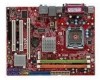
MS-7507 Mainboard Mainboard Layout Top : mouse Bottom:keyboard CPUFAN1 Parallel port Bottom: COM port VGA port ATX1 JPW1 T: 1394 port(optional) B: USB ports Top: LAN Jack Bottom: USB ports Intel 945GC SYSFAN2 JCI1 JTPM1 (optional) JSPI1 T:Line-In M:Line-Out B:Mic T:RS-Out M:CS-Out B:SS- - MSI 945GCM7-F | User Guide - Page 14
Packing Checklist Getting Started MSI motherboard MSI Driver/Utility CD SATA Cable Power Cable Standard Cable for IDE Devices Back IO Shield User's Guide * The pictures are for reference only and may vary from the packing contents of the product you purchased. 1-5 - MSI 945GCM7-F | User Guide - Page 15
Hardware Setup Chapter 2 Hardware Setup This chapter provides you with the information about hardware setup procedures. While doing the installation, be careful in holding the components and follow the installation procedures. For some components, if you install in the wrong orientation, the - MSI 945GCM7-F | User Guide - Page 16
MS-7507 Mainboard Quick Components Guide SYSFAN1, p.2-14 JCI1, p.2-14 JPW1, p.2-9 JTPM1, CPU, p.2-17 p.2-3 CPUFAN1,DDR2, p.2-14 p.2-7 Back Panel, p.2-10 SYSFAN2, p.2-14 ATX1, p.2-9 PCIE, p.2-20 PCI, p.2-20 IDE1, p.2-12 JSPD1, p.2-15 JFP2, p.2-16 SATA1~4, p.2-13 JFP1, p.2-16 CD_IN1, - MSI 945GCM7-F | User Guide - Page 17
doing overclocking. Any attempt to operate beyond product specifications is not recommended. We do not guarantee the damages or risks caused by inadequate operation or beyond product specifications. Introduction to LGA 775 CPU The pin-pad side of LGA 775 CPU. The surface of LGA 775 CPU. Remember - MSI 945GCM7-F | User Guide - Page 18
MS-7507 Mainboard CPU & Cooler Installation W hen you are installing the CPU, make sure the CPU has a cooler attached on the top to prevent overheating. Meanwhile, do not forget to apply some thermal paste on CPU before installing the heat sink/cooler fan for better heat dispersion. Follow the - MSI 945GCM7-F | User Guide - Page 19
Setup 5. Lift the load lever up and open the load plate. 6. After confirming the CPU direction for correct mating, put down the CPU in the socket housing frame. Be sure to grasp on the edge of the CPU base. Note that the alignment keys are matched. alignment key 7. Visually inspect if the - MSI 945GCM7-F | User Guide - Page 20
it) to lock the h ook s . 12. Turn over the mainboard to confirm that the clip-ends are correctly inserted. locking switch Important 1. Read the CPU status in BIOS (Chapter 3). 2. Whenever CPU is not installed, always protect your CPU socket pin with the plastic cap covered (shown in Figure 1) to - MSI 945GCM7-F | User Guide - Page 21
Hardware Setup Memory These DIMM slots are used for installing memory modules. For more information on compatible components, please visit http://global.msi.com. tw/index.php?func=testreport DDR2 240-pin, 1.8V 64x2=128 pin 56x2=112 pin Dual-Channel: Channel A in GREEN; Channel B in ORANGE Dual - MSI 945GCM7-F | User Guide - Page 22
MS-7507 Mainboard Installing Memory Modules 1. The memory module has only one notch on the center and will only fit in the right orientation. 2. Insert the memory module - MSI 945GCM7-F | User Guide - Page 23
Power Connector: JPW1 This 12V power connector is used to provide power to the CPU. JPW1 42 31 Pin Definition PIN SIGNAL 1 GND 2 GND 3 12V 4 connected to proper ATX power supplies to ensure stable operation of the mainboard. 2. Power supply of 350 watts (and above) is highly recommended - MSI 945GCM7-F | User Guide - Page 24
MS-7507 Mainboard Back Panel Mouse Keyboard Parallel Port 1394 Port (optional) Type A L-In RS-Out LAN L-Out CS-Out Serial Port VGA Port Mouse Parallel Port USB Ports Mic SS-Out 1394 Port (optional) Type B L-In / RS-Out LAN Keyboard L-Out Serial Port VGA Port USB Ports Mic / CS- - MSI 945GCM7-F | User Guide - Page 25
on the LAN. Off 10 Mbit/sec data rate is selected. On 100 Mbit/sec data rate is selected. On 1000 Mbit/sec data rate is selected. Audio Ports (Type A) These audio connectors are used for audio devices. You can differentiate the color of the audio jacks for different audio sound effects. Line - MSI 945GCM7-F | User Guide - Page 26
MS-7507 Mainboard Connectors Floppy Disk Drive Connector: FDD1 This connector supports 360KB, 720KB, 1.2MB, 1.44MB or 2.88MB floppy disk drive. FDD1 IDE Connector: IDE1 This connector supports IDE hard disk to IDE device's documentation supplied by the vendors for jumper setting instructions. 2-12 - MSI 945GCM7-F | User Guide - Page 27
~ SATA4 This connector is a high-speed Serial ATA interface port. Each connector can connect to one Serial ATA device. SATA4 SATA3 SATA2 SATA1 supported by ICH7/ICH7R(optional) Important Please do not fold the Serial ATA cable into 90-degree angle. Otherwise, data loss may occur during transmission - MSI 945GCM7-F | User Guide - Page 28
MS-7507 Mainboard Fan Power Connectors: CPUFAN1, SYSFAN1~2 The fan power connectors support system CPU fans at processor's official website or consult the vendors for proper CPU cooling fan. 2. CPUFAN1 / SYSFAN1 / SYSFAN2 supports fan control. You can adjust fan speed in H/W Monitor menu of BIOS - MSI 945GCM7-F | User Guide - Page 29
TPBCable power Ground IEEE1394 Bracket (Optional) S/PDIF-Out Connector: JSPD1 This connector is used to connect S/PDIF (Sony & Philips Digital Interconnect Format) interface for digital audio transmission. JSPD1 GND SPDIF VCC S/PDIF Bracket (Optional) 2-15 - MSI 945GCM7-F | User Guide - Page 30
MS-7507 Mainboard Front Panel Connectors: JFP1, JFP2 These connectors are for electrical connection to the front panel switches and LEDs. The JFP1 is compliant with Intel® Front Panel I/O Connectivity Design Guide : CD_IN1 This connector is provided for external audio input. CD_IN1 2-16 L GND R - MSI 945GCM7-F | User Guide - Page 31
connector allows you to connect the front panel audio and is compliant with Intel® Front Panel I/O Connectivity Design Guide. 2 1 10 9 JAUD1 PIN SIGNAL Platform Module) module (optional). Please refer to the TPM security platform manual for more details and usages. JTPM 1 2 14 1 13 Pin - MSI 945GCM7-F | User Guide - Page 32
MS-7507 Mainboard Front USB Connector: JUSB1 ~ 2 These connectors, compliant with Intel® I/O Connectivity Design Guide, is ideal for connecting high-speed USB interface peripherals such as USB HDD, digital cameras, MP3 players, printers, modems and the like. JUSB1~2 2 10 1 9 Pin - MSI 945GCM7-F | User Guide - Page 33
shorting 2-3 pin while the system is off. Then return to 1-2 pin position. Avoid clearing the CMOS while the system is on; it will damage the mainboard. 2-19 - MSI 945GCM7-F | User Guide - Page 34
MS-7507 Mainboard Slots PCI (Peripheral Component Interconnect) Express Slots The PCI Express slot supports the PCI Express interface expansion card. The PCI Express x 16 supports up to 4.0 GB/s transfer rate. The PCI Express x 1 supports up to 250 MB/s transfer rate. PCI Express x16 slot PCI - MSI 945GCM7-F | User Guide - Page 35
Hardware Setup PCI Interrupt Request Routing The IRQ, acronym of interrupt request line and pronounced I-R-Q, are hardware lines over which devices can send interrupt signals to the microprocessor. The PCI IRQ pins are typically connected to the PCI bus pins as follows: PCI Slot 1 PCI Slot 2 - MSI 945GCM7-F | User Guide - Page 36
This chapter provides information on the BIOS Setup program and allows you to configure the system for optimum use. You may need to run the Setup program when: ² An error message appears - MSI 945GCM7-F | User Guide - Page 37
MS-7507 Mainboard Entering Setup Power BIOS maker as A = AMI, W = AWARD, and P = PHOENIX. 2nd - 5th digit refers to the model number. 6th digit refers to the chipset as I = Intel, N = nVidia, and V = VIA. 7th - 8th digit refers to the customer as MS = all standard customers. V1.1 refers to the BIOS - MSI 945GCM7-F | User Guide - Page 38
BIOS Setup Control Keys Enter> Move to the sub-menu. If you want to return to the main menu, just press the . General Help The BIOS setup program provides a General Help screen. You can call up this screen from any menu by simply pressing . The - MSI 945GCM7-F | User Guide - Page 39
MS-7507 Mainboard The Main Menu Standard CMOS Features Use this menu for basic system configurations, such as time, date etc. Advanced BIOS Features Use for power management. PNP/PCI Configurations This entry appears if your system supports PnP/PCI. H/W Monitor This entry shows your PC health status. - MSI 945GCM7-F | User Guide - Page 40
Setup Load Optimized Defaults Use this menu to load the default values set by the mainboard manufacturer specifically for optimal performance of the mainboard. BIOS Setting Password Use this menu to set the password for BIOS. Save & Exit Setup Save changes to CMOS and exit setup. Exit Without Saving - MSI 945GCM7-F | User Guide - Page 41
MS-7507 Mainboard > . day Day of the week, from Sun to Sat, determined by BIOS. Read-only. month The month from Jan. through Dec. date The date from can be keyed by numeric function keys. year The year can be adjusted by users. Time (HH:MM :SS) This allows you to set the system time - MSI 945GCM7-F | User Guide - Page 42
BIOS Setup Device / Vender / Size It will showing the device information that you connected to the SATA connector. LBA/Large M ode This allows you to enable or disable the LBA Mode. Setting to Auto enables LBA mode if the device supports IDE/ SATA connector on the mainboard. Floppy A This item allows - MSI 945GCM7-F | User Guide - Page 43
MS-7507 Mainboard System Information Press to enter the sub-menu, and the following screen appears. This sub-menu shows the CPU information, BIOS version and memory status of your system (read only). 3-8 - MSI 945GCM7-F | User Guide - Page 44
Advanced BIOS Features BIOS Setup key when the system is powered on. Setting to [Off] will allow users to use the arrow keys on the numeric keypad. IOAPIC Function This Programmable Interrupt Controller). Due to compliance with PC2001 design guide, the system is able to run in APIC mode. Enabling - MSI 945GCM7-F | User Guide - Page 45
MS-7507 Mainboard MPS Table Version This field allows you to select which MPS (Multi-Processor Specification) version to be used for the operating system. You need to select the MPS version supported by your operating system. To find out which version to use, consult the vendor of your operating - MSI 945GCM7-F | User Guide - Page 46
BIOS Setup TCG/TPM SUPPORT This setting allows you to enable/disable the TCG/TPM. Excute TPM Command This item allows you to enable or disable the TPM security chip. Clearing the TPM This item allows you to clear the user information saved in the TPM security chip. W hen you press , a warning - MSI 945GCM7-F | User Guide - Page 47
MS-7507 Mainboard Integrated Peripherals USB Controller This setting allows you to enable/disable the onboard USB controller. USB Device Legacy Support Select [Enabled] if you need to use a USB-interfaced device in the operating system. Onboard LAN Controller This item is used to enable/disable the - MSI 945GCM7-F | User Guide - Page 48
BIOS Setup On-Chip SATA Controller These items allow users to enable or disable the SATA controller. RAID for the first serial port. Parallel Port There is a built-in parallel port on the on-board Super I/O chipset that provides Standard, ECP, and EPP features. It has the following options: [ - MSI 945GCM7-F | User Guide - Page 49
MS-7507 Mainboard Power Management Setup Important S3-related functions described in this section are available only when your BIOS supports S3 mode is a low power state. In this state, no system context is lost (CPU or chipset) and hardware maintains all system context. [S3] The S3 sleep mode is - MSI 945GCM7-F | User Guide - Page 50
BIOS Setup Suspend Time Out (Minute) If system activity is not detected for the length of time specified in this field, all devices except CPU will be shut off. Power Button Function This feature sets the function of the power button. Settings are: [On/ Off] The power button functions as - MSI 945GCM7-F | User Guide - Page 51
MS-7507 Mainboard PNP/PCI Configurations This section describes configuring the PCI bus system and PnP (Plug & Play) feature. PCI, or Peripheral Component Interconnect, is a system which allows I/O devices to operate at speeds nearing the speed the CPU itself uses when communicating with its special - MSI 945GCM7-F | User Guide - Page 52
IRQs passed to devices that are configurable by the system BIOS. The available IRQ pool is determined by reading the ESCD NVRAM. If more IRQs must be removed from the IRQ pool, the end user can use these settings to reserve the IRQ by assigning an [Reserved] service required by the I/O device. 3-17 - MSI 945GCM7-F | User Guide - Page 53
MS-7507 Mainboard H/W Monitor Chassis Intrusion The field enables or disables the feature Enabled] later. CPU Smart FAN Target The mainboard provides the Smart Fan function which can control the CPU fan speed automatically depending on the current temperature to keep it with in a specific range. You - MSI 945GCM7-F | User Guide - Page 54
This item allows you to set the CPU FSB frequency (in MHz). Adjust CPU Ratio This field appears only when the CPU supports this function. This item allows you to set the CPU ratio. Adjusted CPU Frequency It shows the adjusted CPU frequency (FSB x Ratio). Read-only. Advance DRAM Configuration - MSI 945GCM7-F | User Guide - Page 55
MS-7507 Mainboard Spectrum W hen the motherboard's clock generator pulses, the . If you do not have any EMI problem, leave the setting at Disabled for optimal system overclocking because even a slight jitter can introduce a temporary boost in clock speed which may just cause your overclocked processor - MSI 945GCM7-F | User Guide - Page 56
BIOS Setup Important 1. If you do not have any EMI problem, leave the setting at [Disabled] for optimal system disable Spread Spectrum if you are overclocking because even a slight jitter can introduce a temporary boost in clock speed which may just cause your overclocked processor to lock up. 3-21 - MSI 945GCM7-F | User Guide - Page 57
MS-7507 Mainboard Load Fail-Safe/ Optimized Defaults The two options on the main menu allow users to restore all of the BIOS settings to the default Fail-Safe or Optimized values. The Optimized Defaults are the default values set by the mainboard manufacturer specifically for optimal performance of - MSI 945GCM7-F | User Guide - Page 58
BIOS Setup BIOS Setting Password W hen you select this function, a message as below will appear on the screen: Type the password, up to six characters in length, and - MSI 945GCM7-F | User Guide - Page 59
MS-7507 Mainboard 3-24 - MSI 945GCM7-F | User Guide - Page 60
, helps users to monitor or configure the hardware status of MSI Mainboard & MSI Graphics card in windows, such as CPU/GPU clock, voltage, fan speed and temperature. Before you install the Dual CoreCenter, please make sure the system has meet the following requirements: 1. Intel Pentium4 / Celeron - MSI 945GCM7-F | User Guide - Page 61
MS-7507 Mainboard Activating Dual Core Center Once you have your Dual Core Center installed (locate the setup source file in the setup CD accompanying with your mainboard, path: Utility --> MSI Utility --> Dual Core Center), it will have an icon in the system tray, a short cut icon on the - MSI 945GCM7-F | User Guide - Page 62
status of the MSI mainboard would be available. Introduction: Click each button appearing above to enter sub-menu to make further configuration or to execute the function. MB Click MB button to read current CPU temperature, FSB and CPU clock of mainboard will show below. VGA Click VGA button to read - MSI 945GCM7-F | User Guide - Page 63
MS-7507 Mainboard AV/ Game/ Office/ Silence/ Cool MSI provides five common settings for different environments. The card. Temperature In this sub-menu, you can monitor the temperatures of MB and graphics card. User Profile In this sub-menu, you can set the values of clock, voltage and fan speed by - MSI 945GCM7-F | User Guide - Page 64
-UP Rate button DOT FSB-DOWN Rate button Important Even though the Dynamic Overclocking Technology is more stable than manual overclocking, basically, it is still risky. We suggest user to make sure that your CPU can afford to overclock regularly first. If you find the PC appears to be unstable or - MSI 945GCM7-F | User Guide - Page 65
MS-7507 Mainboard Clock In the Clock sub-menu, you can see clock status (including FSB/ CPU clock of mainboard and GPU/ memory clock of graphics card) of your system. And you can select desired value for overclocking. There will be several items for you to select for overclocking after you - MSI 945GCM7-F | User Guide - Page 66
your system, and you can select desired value for overclocking. It will show several items to select for overclocking after you click the button. You can click the up with red color will be shown. Important In the user profile, clicking the Save button can save the changes to it. In the default - MSI 945GCM7-F | User Guide - Page 67
MS-7507 Mainboard FAN Speed In the FAN Speed sub-menu, you can read fan color will be shown. Important 1. When you set the fan speed manually, please make sure to disabled the "CPU Smart FAN Target" item in the BIOS. 2. In the user profile, clicking the Save button can save the changes to it. In - MSI 945GCM7-F | User Guide - Page 68
Dual Core Center Temperature In the Temperature sub-menu, you can see temperature status of your system. On the underside, it shows the graphs of the temperatures. Only the curves of the item which the button is lit up with red color will be shown. A-9 - MSI 945GCM7-F | User Guide - Page 69
MS-7507 Mainboard User Profile In the User Profile sub-menu, click the setting button that besides the user profile bar, and the next screen will appear. Here you can define the clock/ fan speed/ voltage by your need, click the button to choose a - MSI 945GCM7-F | User Guide - Page 70
speed is lower than the threshold you defined, the system will pop up a warning message. After setting all values you need, you can change the user profile name in the box then click the save button to save all changes in a profile. Finally, you can choose the - MSI 945GCM7-F | User Guide - Page 71
SATA RAID Appendix B Intel ICH7R SATA RAID The ICH7R provides a hybrid solution that combines four independent SATAII ports for support of up to four Serial ATAII (Serial ATAII RAID) drives. It offers RAID level 0 (Striping), RAID level 1 (Mirroring and Duplexing), RAID level 5 (Block Interleaved - MSI 945GCM7-F | User Guide - Page 72
MS-7507 Mainboard ICH7R Introduction The ICH7R provides a hybrid solution that combines four independent SATAII ports for support of up to RAID 1 mirrors are created, and a RAID 0 stripe is created over these. Intel Matrix RAID Technology is the advanced ability for two RAID volumes to share the - MSI 945GCM7-F | User Guide - Page 73
should be integrated with the system BIOS on all motherboards with a supported Intel chipset. The Intel Matrix Stroage Manager Option ROM is the Intel RAID implementation and provides BIOS and DOS disk services. Please use + keys to enter the "Intel(R) RAID for Serial ATA" status screen - MSI 945GCM7-F | User Guide - Page 74
MS-7507 Mainboard After pressing the and keys simultaneously, the following window will appear: (1) Create RAID Volume 1. Select option 1 "Create RAID Volume" and press key. The - MSI 945GCM7-F | User Guide - Page 75
Intel ICH7R SATA RAID 3. In the Disk field, press key and the following screen appears. Use key to select the disks you want to - MSI 945GCM7-F | User Guide - Page 76
MS-7507 Mainboard Important Since you want to create two volumes (Intel Matrix RAID Technology), this default size (maximum) needs to be reduced. Type in a new size for the first volume. As an example: if you want - MSI 945GCM7-F | User Guide - Page 77
that all data on RAID drives will be lost. Important If your system currently boots to RAID and you delete the RAID volume in the Intel RAID Option ROM, your system will become unbootable. Select option 2 Delete RAID Volume from the main menu window and press key to select a RAID - MSI 945GCM7-F | User Guide - Page 78
MS-7507 Mainboard (3) Reset Disks to Non-RAID Select option 3 Reset Disks to Non-RAID and press to delete the RAID volume and remove any RAID structures - MSI 945GCM7-F | User Guide - Page 79
For ICH7R (NH82801GR) into drive A: and press . Important Please follow the instruction below to make an "Intel IAA RAID XP Driver For ICH7R (NH82801GR)" for yourself. 1. Insert the MSI CD into the CD-ROM drive. 2. Click the "Browse CD" on the Setup screen. 3. Copy all the contents in the - MSI 945GCM7-F | User Guide - Page 80
MS-7507 Mainboard Installation of Intel Matrix Storage Console The Intel Application Accelerator RAID Edition driver may be used to operate the hard drive from which the system is booting or a hard drive that contains important data. For this reason, you cannot remove or un-install this driver from - MSI 945GCM7-F | User Guide - Page 81
Intel ICH7R SATA RAID The InstallShield Wizard will begin automatically for installation showed as following: Click on the Next button to proceed the installation in the welcoming window. B-11 - MSI 945GCM7-F | User Guide - Page 82
MS-7507 Mainboard The window shows the components to be installed. Click Next button to continue. After reading the license agreement in the following window, click Yes button to continue. B-12 - MSI 945GCM7-F | User Guide - Page 83
Intel ICH7R SATA RAID Select the folder in which you want the program to be installed in the following window, and click Next button to start installation. Select a program folder in the following window where you want Setup to add the program icon. B-13 - MSI 945GCM7-F | User Guide - Page 84
MS-7507 Mainboard The following window appears to show the Intel Application Accelerator RAID Edition Setup installation status. Once the installation is complete, the following window appears. B-14 - MSI 945GCM7-F | User Guide - Page 85
Chip SATA Setting for properly setting of the BIOS. 2. Install the Intel Application Accelerator RAID Driver during W indows Setup. Refer to Installing Software for instructions on installing the driver during W indows Setup. 3. Install the Intel Matrix Storage Console after the operating system is - MSI 945GCM7-F | User Guide - Page 86
MS-7507 Mainboard Create RAID Volume from Existing Disk To create a RAID volume from an existing disk, choose Action --> Create RAID Volume from Existing Hard Drive. The Create RAID Volume from Existing Hard Drive Wizard pops up to lead you for the following procedure. Click Next to continue. B-16 - MSI 945GCM7-F | User Guide - Page 87
Intel ICH7R SATA RAID (1) Step 1: Configure Volume Here you can configure the new RAID volume by entering the volume name, selecting the RAID level and strip - MSI 945GCM7-F | User Guide - Page 88
MS-7507 Mainboard setting for most users, you should choose the strip size value which is best suited to your specific RAID usage model. Port 1) the single disk is attached to. You can also use the Intel Application Accelerator RAID Edition utility before the second disk is installed to verify - MSI 945GCM7-F | User Guide - Page 89
Intel ICH7R SATA RAID (3) Select Member Hard Drive(s) Then select the member disk (the target disk) that you wish to use and then click "-->" to move - MSI 945GCM7-F | User Guide - Page 90
MS-7507 Mainboard (4) Specify Volume Size Specify the amount of available array space to the rest hard drive space will be worked as RAID 1 volume, which is the new technology called Intel Matrix RAID. Then click Next to continue. (5) Start Creating RAID Volume from Existing Hard Drive Wizard Before - MSI 945GCM7-F | User Guide - Page 91
Intel ICH7R SATA RAID (6) Start Migration The migration process may take up to two hours to complete depending on the size of the disks being used - MSI 945GCM7-F | User Guide - Page 92
MS-7507 Mainboard Degraded RAID Array A RAID 1, RAID 5 or RAID 10 volume is reported hard drive with a new one that is of equal or greater c ap ac i t y. 3. Reboot the system to Intel RAID Option ROM by press and keys simultaneously during the Power-On Self Test (POST). 4. Select the port - MSI 945GCM7-F | User Guide - Page 93
system. 6. W hen prompted to rebuild the RAID volume, click 'Yes'. 7. The Intel(R) Storage Utility will be launched. Right-click the new hard drive and select 'Rebuild to this Disk'. The 'Rebuild W izard' will be launched which will guide you through the process of rebuilding to the new hard drive
-
 1
1 -
 2
2 -
 3
3 -
 4
4 -
 5
5 -
 6
6 -
 7
7 -
8
-
9
-
10
-
11
-
12
-
13
-
14
-
15
-
16
-
17
-
18
-
19
-
20
-
21
-
22
-
23
-
24
-
25
-
26
-
27
-
28
-
29
-
30
-
31
-
32
-
33
-
34
-
35
-
36
-
37
-
38
-
39
-
40
-
41
-
42
-
43
-
44
-
45
-
46
-
47
-
48
-
49
-
50
-
51
-
52
-
53
-
54
-
55
-
56
-
57
-
58
-
59
-
60
-
61
-
62
-
63
-
64
-
65
-
66
-
67
-
68
-
69
-
70
-
71
-
72
-
73
-
74
-
75
-
76
-
77
-
78
-
79
-
80
-
81
-
82
-
83
-
84
-
85
-
86
-
87
-
88
-
89
-
90
-
91
-
92
-
93
 |
 |

945GCM7 series
MS-7507 (v1.X) Mainboard