MSI Eclipse SLI User Guide
MSI Eclipse SLI - Motherboard - ATX Manual
 |
UPC - 816909051643
View all MSI Eclipse SLI manuals
Add to My Manuals
Save this manual to your list of manuals |
MSI Eclipse SLI manual content summary:
- MSI Eclipse SLI | User Guide - Page 1
ECLIPSE Series MS-7520 (v1.X) Mainboard i - MSI Eclipse SLI | User Guide - Page 2
's manual, please contact your place of purchase or local distributor. Alternatively, please try the following help resources for further guidance. Visit the MSI website for FAQ, technical guide, BIOS updates, driver updates, and other information: http://global.msi.com.tw/index.php? func=service - MSI Eclipse SLI | User Guide - Page 3
instructions carefully. 2. Keep this User's Manual Unplug the Power Cord before inserting any add-on card or module. 9. All cautions and warnings on the equipment should be the following situations arises, get the equipment checked by a service personnel: † The power cord or plug is damaged. † - MSI Eclipse SLI | User Guide - Page 4
if not installed and used in accordance with the instructions, may cause harmful interference to radio communications. However, limits. VOIR LANOTICE D'INSTALLATIONAVANT DE RACCORDER AU RESEAU. Micro-Star International MS-7520 This device complies with Part 15 of the FCC Rules. Operation is subject - MSI Eclipse SLI | User Guide - Page 5
WEEE (Waste Electrical and Electronic Equipment) Statement v - MSI Eclipse SLI | User Guide - Page 6
vi - MSI Eclipse SLI | User Guide - Page 7
vii - MSI Eclipse SLI | User Guide - Page 8
Revision History ...ii Technical Support ...ii Safety Instructions ...iii FCC-B Radio 2-1 Quick Components Guide 2-2 CPU (Central Processing Unit 2-3 Memory ...2-7 Power Supply BIOS Features 3-8 Integrated Peripherals 3-11 Power Management Setup 3-14 H/W Monitor ...3-17 Green Power ...3-18 BIOS - MSI Eclipse SLI | User Guide - Page 9
Configuration A-9 Appendix B Overclocking Center B-1 Activating Overclocking Center B-2 System Info ...B-3 DOT ...B-5 Appendix C Intel ICH10R SATA RAID C-1 Introduction ...C-2 BIOS Configuration C-3 Installing Driver C-10 Installing Software C-12 RAID Migration Instructions C-16 Recovery - MSI Eclipse SLI | User Guide - Page 10
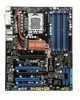
you for choosing the Eclipse (MS-7520 v1.X) ATX mainboard. The Eclipse mainboard is based on Intel® X58 & ICH10R chipsets for optimal system ef ficiency. Designed to fit the advanced Intel® i7 LGA1366 processor, the Eclipse delivers a high performance and professional desktop platform solution. 1-1 - MSI Eclipse SLI | User Guide - Page 11
MS-7520 Mainboard Mainboard Specifications Processor Support - Intel® i7 processors in the LGA1366 package (For the latest information about CPU, please visit ht t p: / / gl obal . m si . c om . t w / i ndex. php?func =c puform 2) Supported QPI - Up to 6.4 GT/s Chipset - IOH: Intel® X58 chipset - - MSI Eclipse SLI | User Guide - Page 12
RAID - SATA7 & SATA8 support RAID 0/ 1 & JBOD mode by 1st JMicron JMB322 - SATA9 & SATA10 support RAID 0/ 1 & JBOD mode by 2nd JMicron JMB322 1394 - Supports pinheader - 1 serial port pinheader - 1 TPM Module pinheader - 1 D-LED2 panel pinheader TPM - Supports TPM Slots - 3 PCI Express gen2 x16 slots - MSI Eclipse SLI | User Guide - Page 13
2 PCI _E5 S YSF AN5 ON 123 P OW ER1 RESET 1 DLED2 CPU_CLK1 J USB 2 Intel ICH10R J SM B1 S Y SFA N 3 BATT + JCI1 SATA5_6 SATA2_4 JMB322 SATA7 SATA8 SYSFAN2 I/O Chip JMB363 JUS B1 JMB322 JDLED2 SATA9 SATA10 IDE1 JCOM1 JTPM 1JFP2 JFP1 Eclipse (MS-7520 v1.X) ATX Mainboard SATA1 _3 1-4 - MSI Eclipse SLI | User Guide - Page 14
Packing Checklist Getting Started MSI motherboard MSI Driver/Utility CD Back IO Shield Power Cable SATA Cable IDE Cable CrossFire Video Link Cable external SATA Cable USB Bracket * The pictures are for reference only and may vary from the packing contents of the product you - MSI Eclipse SLI | User Guide - Page 15
MS-7520 Mainboard X-Fi Xtreme Audio Card Set (Card and Driver CD) D-LED2 Panel Set (1 panel & 1 cable) User's Guide and Quick Guide GreenPower Genie Set (1 GreenPower genie & 1 power cable & 1 (2x2 pin) cable) 1-6 - MSI Eclipse SLI | User Guide - Page 16
Hardware Setup Chapter 2 Hardware Setup This chapter provides you with the information about hardware setup procedures. While doing the installation, be careful in holding the components and follow the installation procedures. For some components, if you install in the wrong orientation, the - MSI Eclipse SLI | User Guide - Page 17
MS-7520 Mainboard Quick Components Guide SYSFAN4, p.2-21 SYSFAN2, p.2-21 JPWR2, p.2-16 CPU, p.2-3 CPUFAN, p.2-21 DDR3, p.2-7 Back Panel, p.2-17 JPWR1, p.2-16 PCI_E, p.2-26 SYSFAN3, p.2-21 JSMB1, p.2-24 SATA, p.2-20 SYSFAN1, p.2-21 - MSI Eclipse SLI | User Guide - Page 18
://global.msi.com. overclocking. Any attempt to operate beyond product specifications is not recommended. We do not guarantee the damages or risks caused by inadequate operation or beyond product specifications. Introduction to LGA 1366 CPU The pin-pad side of LGA 1366 CPU. The surface of LGA 1366 - MSI Eclipse SLI | User Guide - Page 19
MS-7520 Mainboard CPU & Cooler Installation W hen you are installing the CPU, make sure the CPU the load level. 2. Lift the load lever up and open the load plate. 3. The CPU socket has a plastic cap on it to protect the contack from damage. Before you install CPU, always cover it to protect the - MSI Eclipse SLI | User Guide - Page 20
Hardware Setup 5. Visually inspect if the CPU is seated well into the socket. If not, take out the CPU with pure vertical motion and reinstall. 6. C over the load plate onto your CPU cooler is firmly installed before turning on your system. 2. Do not touch the CPU socket pins to avoid damaging. 2-5 - MSI Eclipse SLI | User Guide - Page 21
MS-7520 Mainboard 9. Align the holes on the mainboard with the heatsink. Push inserted. Mainboard locking switch Hook Important 1. Read the CPU status in BIOS. 2. Whenever CPU is not installed, always protect your CPU socket pin with the plastic cap covered (shown in Figure 1) to avoid - MSI Eclipse SLI | User Guide - Page 22
, please visit http://global.msi.com. tw/index.php?func=testreport DDR3 240-pin, 1.5V 48x2=96 pin 72x2=144 pin Memory Population Rules Please refer to the following illustrations for memory population rules. Single-Channel mode W hen you have only one memory module, please always insert it - MSI Eclipse SLI | User Guide - Page 23
MS-7520 Mainboard Three-Channel mode In Three-Channel mode, the memory modules can transmit and receive data with three data bus lines simultaneously. Enabling Three-Channel mode can enhance the best system performance. W hen you have three or more memory modules, please always insert them as the - MSI Eclipse SLI | User Guide - Page 24
the DIMM _A0 first. - Due to the chipset resource deployment, the system density will only be detected up to 23+GB (not full 24GB) when each DIMM is installed with a 4GB memory module. - When you install incorrect memory module (the SA2-pin of the memory module connects to Ground) in the DIMM_C0/C1 - MSI Eclipse SLI | User Guide - Page 25
MS-7520 Mainboard Installing Memory Modules 1. The memory module has only one notch on the center and will only fit in the right orientation. 2. Insert the memory module vertically into the DIMM slot. Then push it in until the golden finger on the memory module is deeply inserted in the DIMM slot. - MSI Eclipse SLI | User Guide - Page 26
slot A1 A0 B1 B0 C1 C0 V V V V VVVV Compatible DDR3 1066 memory list Please refer to the following list to find the available DDR3 1066 memory modules. Vendor Aeneon Model Aeneon AEH660UD00-10FA98X(Aeneon AEH93R10F) ELPIDA EBJ51UD8BAFA-AC-E(ELPIDA J5308BASE) Qimonda IMSH51U03A1F1C-10F - MSI Eclipse SLI | User Guide - Page 27
MS-7520 Mainboard Vendor Micron Model MT8JTF12864AY-1G1D1(Micron 1GB 1GB 1GB 1GB 1GB 1GB 1GB 1GB 2GB 2GB 2GB 2GB 2GB 2GB 2GB 2GB 2GB 2GB Memory slot A1 A0 B1 B0 C1 C0 V V V V V VV V V V V V V V VV V V V V V V V VV V V V V VVVV V V VVVV V V V V V VV V V V - MSI Eclipse SLI | User Guide - Page 28
512MB 512MB 1GB 1GB 1GB 1GB 1GB 1GB 1GB 1GB 1GB 1GB 1GB 1GB 1GB 1GB 1GB 1GB Memory slot A1 A0 B1 B0 C1 C0 V V V V V VV V V V V VVVV V V VVVV V V VVVV V V V V V VV V V V V V V V VV V V VVVVVV V V V V V VV V V V V V V V VV V V V V V V V VV - MSI Eclipse SLI | User Guide - Page 29
MS-7520 Mainboard Vendor TAKEMS Model TMS1GB364D081-107EQ (With iron case) Bufaullo D3/1066-2G ( list Please refer to the following list to find the available DDR3 1066 memory modules. Vendor Qimonda Model IMNH51U03A1F1C-13G (With iron case) Qimonda IMSH51U03A1F1C-13H (Qimonda IDSH51-03A1F1C- - MSI Eclipse SLI | User Guide - Page 30
-HCH9) Size 1GB 1GB 1GB 1GB 1GB 1GB 1GB 2GB 2GB 2GB 2GB 2GB 2GB 2GB Memory slot A1 A0 B1 B0 C1 C0 V V V V V VV V V V V V V V VV V V V V V VV V V Important For more information on compatible components, please visit http://global. msi.com.tw/index.php?func=testreport. 2-15 - MSI Eclipse SLI | User Guide - Page 31
MS-7520 Mainboard Power Supply ATX 24-Pin Power Connector: JPWR1 This connector allows you to connect an ATX 24-pin power supply. To connect the ATX - MSI Eclipse SLI | User Guide - Page 32
Back Panel Mouse USB Ports Keyboard Hardware Setup LAN LAN 1394 Port eSATA Ports USB Ports Clear CMOS Button USB Ports M ouse/K ey boar d The standard PS/2® mouse/keyboard DIN connector is for a PS/2® mouse/keyboard. 1394 Port The IEEE1394 port on the back panel provides connection to - MSI Eclipse SLI | User Guide - Page 33
MS-7520 Mainboard LAN The standard RJ-45 LAN jack is for connection Yellow to the Local Area Network (LAN). You can connect a network cable to it. Green / Orange LED Color Left Yellow Green Right Orange LED State Condition Off LAN link is - MSI Eclipse SLI | User Guide - Page 34
Hardware Setup Connectors IDE Connector: IDE1 This connector supports IDE hard disk drives, optical disk drives and other IDE devices. Important If you install two IDE / slave mode by setting jumpers. Refer to IDE device's documentation supplied by the vendors for jumper setting instructions. 2-19 - MSI Eclipse SLI | User Guide - Page 35
-degree angle. Otherwise, data loss may occur during transmission. 2. Please always use the Intel default Black SATA connectors (SATA1~6) fir s t. 3. SATA7 & SATA8, SATA9 & SATA10, support RAID 0/ RAID 1/ JBOD function and you can set RAID mode in BIOS setup or in DRIVE BOOSTER MANAGER (refer to the - MSI Eclipse SLI | User Guide - Page 36
the mainboard has a System Hardware Monitor chipset on-board, you must use a Overclocking Center utility that will automatically control the CPU fan speed according to the actual CPU temperature. 3. SYSFAN1~3 support fan control, too. You may select how percentage of speed for the SYSFAN1/2/3 in BIOS - MSI Eclipse SLI | User Guide - Page 37
MS-7520 Mainboard Front Panel Connectors: JFP1, JFP2 These connectors are for electrical connection to the front panel switches and LEDs. The JFP1 is compliant with Intel® Front Panel I/O Connectivity Design Guide. PIN Power Power LED Switch 1 +- 2 JFP1 2 1 10 3 9 4 +- -+ 5 HDD Reset - MSI Eclipse SLI | User Guide - Page 38
Connector: JTPM1 This connector connects to a TPM (Trusted Platform Module) module (optional). Please refer to the TPM security platform manual for more details and usages. 2 14 1 13 Pin Signal To clear the warning, you must enter the BIOS utility and clear the record. GND 2 CINTRU 1 JCI1 2-23 - MSI Eclipse SLI | User Guide - Page 39
MS-7520 Mainboard Front USB Connector: JUSB1/ JUSB2 These connectors, compliant with Intel® I/O Connectivity Design Guide, is ideal for connecting high-speed USB interface peripherals such as USB HDD, digital cameras, MP3 players, printers, modems and the like. JUSB1/ JUSB2 2 10 1 9 - MSI Eclipse SLI | User Guide - Page 40
buttons for you to set the computer's function. This section will explain how to change your motherboard's function through the use of button. Power Button: POWER1 This power button is used to the menu on D-LED2 panel. Please refer to the D-LED2 quick guide for more details and usages. DLED2 2-25 - MSI Eclipse SLI | User Guide - Page 41
MS-7520 Mainboard Slots PCI (Peripheral Component Interconnect) Express Slot The PCI Express slot supports the PCI Express interface expansion card. The PCI Express 2.0 x16 supports up to 8.0 GB/s transfer rate. The PCI Express 2.0 x4 supports up to 2.0 GB/s transfer rate. The PCI Express x1 - MSI Eclipse SLI | User Guide - Page 42
have to enable the CrossFireX in BIOS by yourself. Following the process below to complete CrossFireX: 1. Install the CrossFire Edition graphics card in the First Only Windows® XP with Service Pack 2 (SP2)& Windows® XP Profes -sional x64 Edition & Windows® Vista support the CrossFire function. 2-27 - MSI Eclipse SLI | User Guide - Page 43
MS-7520 Mainboard 3.W hen all of the hardware and software has been properly set up and installed, reboot the system. After entering the O.S., click the "Catalyst™ Control Center" icon on the desktop. There is a setting in the Catalyst™ Control Center that needs to be enabled for CrossFire™ to - MSI Eclipse SLI | User Guide - Page 44
Setup PCI (Peripheral Component Interconnect) Slot The PCI slot supports LAN card, SCSI card, USB card, and other add hardware or software settings for the expansion card, such as jumpers, switches or BIOS configuration. PCI Interrupt Request Routing The IRQ, acronym of interrupt request line and - MSI Eclipse SLI | User Guide - Page 45
MS-7520 Mainboard Switch Hardware Overclock Base clock Switch: CPU_CLK1 You can overclock the Base clock to increase the processor frequency by changing this switch. Follow the instructions below to set the CPU clock. ON 123 133 MHz (default) ON 123 166 MHz ON 123 200 MHz Important 1. Make sure - MSI Eclipse SLI | User Guide - Page 46
LED Status Indicators CPU Phase LEDs Hardware Setup DIMM warning LED QPI Phase LEDs IOH Phase LEDs PCIE LED PCIE LED PCIE LED PCI LED PCIE LED PCI LED PCIE LED ON 123 DDR Phase LEDs Power LED Standby LED 2-31 - MSI Eclipse SLI | User Guide - Page 47
MS-7520 Mainboard N am e CPU Phase LEDs QPI Phase LEDs IOH Phase LEDs DDR Phase LEDs PCI E LEDs PCI LEDs Power when the system is in standby (S3/S4/S5 ) status. Lights red when the incorrect memory installed into DIMM_C0/ DIMM_C1 (the DIMMs of 3rd channel). Important You can install the Green Power - MSI Eclipse SLI | User Guide - Page 48
This chapter provides information on the BIOS Setup program and allows you to configure the system for optimum use. You may need to run the Setup program when: ² An error message appears - MSI Eclipse SLI | User Guide - Page 49
V1.0 090108 where: 1st digit refers to BIOS maker as A = AMI, W = AWARD, and P = PHOENIX. 2nd - 5th digit refers to the model number. 6th digit refers to the chipset as I = Intel, N = nVidia, and V = VIA. 7th - 8th digit refers to the customer as MS = all standard customers. V1.0 refers to the - MSI Eclipse SLI | User Guide - Page 50
changes Enter the CPU Spec. menu, and read the CPU information Enter the Memory-Z menu, and read the memory information Load Optimized Defaults to the main menu, just press the . General Help The BIOS setup program provides a General Help screen. You can call up this screen from any - MSI Eclipse SLI | User Guide - Page 51
MS-7520 Mainboard The Main Menu Standard CMOS Features Use this menu for basic system configurations, such as time, date etc. Advanced BIOS Features Use Use this menu to specify the power phase. BIOS Setting Password Use this menu to set the password for BIOS. Cell Menu Use this menu to specify your - MSI Eclipse SLI | User Guide - Page 52
from storage drive (FAT/ FAT32 format only). Load Fail-Safe Defaults Use this menu to load the default values set by the BIOS vendor for stable system performance. Load Optimized Defaults Use this menu to load the default values set by the mainboard manufacturer specifically for optimal performance - MSI Eclipse SLI | User Guide - Page 53
MS-7520 Mainboard Standard CMOS Features The items in Standard CMOS Features Menu includes The format is . day Day of the week, from Sun to Sat, determined by BIOS. Read-only. month The month from Jan. through Dec. date The date from 1 to 31 can be keyed by numeric - MSI Eclipse SLI | User Guide - Page 54
BIOS Setup Device / Vendor / Size It will showing the device information that you connected to the SATA connector. Important IDE Primary Master enter the sub-menu, and the following screen appears. This sub-menu shows the CPU information, BIOS version and memory status of your system (read only). 3-7 - MSI Eclipse SLI | User Guide - Page 55
MS-7520 Mainboard Advanced BIOS Features BIOS Flash Protection W hen enabled, the BIOS' data cannot be changed when attempting to update the BIOS with a Flash utility. To successfully update the BIOS, you'll need to disable this Flash BIOS with PC2001 design guide, the system is able to - MSI Eclipse SLI | User Guide - Page 56
may occur. Execute Bit Support Intel's Execute Disable Bit functionality can prevent certain classes of malicious "buffer overflow" attacks when combined with a supporting operating system. This functionality allows the processor to classify areas in memory by where application code can execute and - MSI Eclipse SLI | User Guide - Page 57
the first/ second/ third boot device where BIOS attempts to load the disk operating system. Trusted Computing Press to enter the sub-menu and the following screen appears: TCG/TPM SUPPORT Setting the option to [Yes] enables TPM (Trusted Platform Module) to the system. Clearing the TPM Press - MSI Eclipse SLI | User Guide - Page 58
Integrated Peripherals BIOS Setup USB Controller This setting allows you to enable/disable the onboard USB controller. USB Device Legacy Support Select controller. RAID Mode (for E-SATA) This item allows you to configure SATA RAID mode. Setting options: [RAID], [AHCI] or [IDE]. Extra RAID/ IDE - MSI Eclipse SLI | User Guide - Page 59
MS-7520 Mainboard Drive Booster Controller #1 (for SATA7 & 8)/ #2(for SATA9 & 10) Press to enter the sub-menu, and the following screen appears. Current Mode This item shows the current SATA mode. Read only. Drive Booster M ode Update: Update To RAID0 (Stripe)/ RAID1(Mirror)/ JBOD(Large)/ - MSI Eclipse SLI | User Guide - Page 60
BIOS Setup AHCI CD/DVD Boot Time out Select the waiting time for the AHCI CD/ DVD when booting. AHCI Port 1/2/3/4/5/6 Press to enter the - MSI Eclipse SLI | User Guide - Page 61
MS-7520 Mainboard Power Management Setup Important S3-related functions described in this section are available only when your BIOS supports this state, no system context is lost (CPU or chipset) and hardware maintains all system context. [S3] The main memory that remains powered while most other hardware - MSI Eclipse SLI | User Guide - Page 62
] allows BIOS to call VGABIOS to initialize the VGA card when system wakes up (resumes) from S3 sleep state. The system resume time is shortened when you disable the function, but system will need an VGA driver to initialize the VGA card. Therefore, if the VGA driver of the card does not support the - MSI Eclipse SLI | User Guide - Page 63
MS-7520 Mainboard Resume by PCI-E Device W hen set to [Enabled], the feature allows your system to be awakened from the power saving modes through any event - MSI Eclipse SLI | User Guide - Page 64
for cooling down automaticlly . SYS FAN1/2/3 Control This item allows users to select how percentage of speed for the SYS FAN1/2/3. PC Health Status CPU/ IOH/ System Temperature, CPU FAN/ SYS FAN1/ SYS FAN2/ SYSFAN3 Speed, CPU Vcore, 3.3V, 5V, 12V These items display the current status of all of the - MSI Eclipse SLI | User Guide - Page 65
MS-7520 Mainboard Green IOH chipset power phase according to the loading of it to reach the best power saving function. DDR Phase Control W hen set to [Auto], the hardware will auto adjust the memory power phase according to the loading of memory to reach the best power saving function. Motherboard - MSI Eclipse SLI | User Guide - Page 66
BIOS Setup BIOS Setting Password W hen you select this function, a message as below will appear on the screen: Type the password, up to six characters in length, and press . The password typed now will replace any previously set password from CMOS memory. You will be prompted to confirm the - MSI Eclipse SLI | User Guide - Page 67
MS-7520 Mainboard Cell Menu Important Change these settings only if you are familiar with the chipset. Current Core / DRAM / QPI Frequency These items show the current clocks of CPU and Memory speed. Read-only. 3-20 - MSI Eclipse SLI | User Guide - Page 68
BIOS Setup CPU Specifications Press to enter the sub-menu and the following screen appears. This sub-menu displays the informations of installed CPU. CPU Technology Support the technologies that the installed CPU supported. Intel EIST The Enhanced Intel SpeedStep technology allows you to set - MSI Eclipse SLI | User Guide - Page 69
MS-7520 Mainboard Base Clock (MHz) This item allows you to set the CPU Base clock (in MHz). You may overclock the CPU by adjusting this value. Please note the overclocking behavior is not guaranteed. Intel Turbo Boost tech This item will appear when you install a CPU with Intel Turbo Boost - MSI Eclipse SLI | User Guide - Page 70
BIOS Setup Adjusted CPU Frequency (M Hz) It shows the adjusted CPU frequency (Base QPI Frequency This item allows you to select the QPI frequency. Memory-Z Press to enter the sub-menu and the following screen appears. DIMM1~6 Memory SPD Information Press to enter the sub-menu and the - MSI Eclipse SLI | User Guide - Page 71
MS-7520 Mainboard Advance DRAM Configuration Press to enter the sub-menu and advance memory timing automatically to be determined by BIOS. Setting to [Manual] allows you to set advanced memory timings. Extreme Memory Profile This item is used to enable/disable the Intel Extreme Memory Profile - MSI Eclipse SLI | User Guide - Page 72
IOH CLK Skew These items are used to select the CPU/ IOH chipset clock skew. They can help CPU to reach the higher overclocking IOH Voltage (V), ICH Voltage (V) These items are used to asjust the voltage of CPU, Memory, QPI and chipset : According to the Inte CPU spec, DRAM Voltage setting 1.65V may - MSI Eclipse SLI | User Guide - Page 73
MS-7520 Mainboard Spread Spectrum W hen the motherboard's clock generator pulses, the extreme values (spikes) of the pulses create EMI (Electromagnetic Interference). The Spread Spectrum function reduces the EMI generated by modulating the pulses so that the spikes of the pulses are reduced to - MSI Eclipse SLI | User Guide - Page 74
BIOS Setup CPU and Memory Clock Overclocking The D.O.T Control, Base Clock, Memory Ratio items for you to overclock the CPU and the Memory. Please refer to the descriptions of these fields for more information. Important 1. CPU Speed = Base clock * CPU Ratio 2. This motherboard supports overclocking - MSI Eclipse SLI | User Guide - Page 75
MS-7520 Mainboard User Settings Save Settings 1/ 2/ 3/ 4 These items are used to save the settings set by yourself to CMOS. Load Settings 1/ 2/ 3/ 4 These items are available after you save your settings in Save Settings 1/ 2/ 3/ 4 items , and are used to load the settings from CMOS. 3-28 - MSI Eclipse SLI | User Guide - Page 76
via the USB/ Storage drive directly. Update BIOS ROM chip data from selected file, which is download from official website and must be saved in the root directory of the USB/ Storage drive. It only supports particular file name, which is the official BIOS file name from us. [USB Drive] After - MSI Eclipse SLI | User Guide - Page 77
MS-7520 Mainboard Important 1. Please refer to the block diagram below about the M-Flash function. Set [BIOS Update] or [USB Drive] in "M-Flash function as" field Select BIOS file from the root directory of USB/ Storage drive (FAT/FAT32 format only) in "Load BIOS source file from" field Save - MSI Eclipse SLI | User Guide - Page 78
Device Please setup a specific folder in specific USB drive/ storage drive to save BIOS file from BIOS ROM chip data. Note: it only supports FAT/ FAT32 file system drive. Save File Name as Please setup a specific name for the BIOS file, which will be saved into the USB drive/ storage drive. Note: we - MSI Eclipse SLI | User Guide - Page 79
MS-7520 Mainboard Load Fail-Safe/ Optimized Defaults The two options on the main menu allow users to restore all of the BIOS settings to the default Fail-Safe or Optimized values. The Optimized Defaults are the default values set by the mainboard manufacturer specifically for optimal performance - MSI Eclipse SLI | User Guide - Page 80
Audio Card The X-Fi Xtreme Audio card is powered by Creative CA0110 Audio chip. It supports up to 8-channel & SPDIF audio effect and allows users to attach 2, 4, 6, or 8 speakers for better surround sound effect. This manual will tell you about the specifications of the card, how to install it to - MSI Eclipse SLI | User Guide - Page 81
MS-7520 Mainboard Introduction X-Fi Xtreme Audio Card is powered by Creative CA0110 Digital Audio Controller. This card provides advanced audio functions by offering a comprehensive suite of - MSI Eclipse SLI | User Guide - Page 82
and General MIDI - Microsoft® DirectSound®, DirectSound 3D & derivatives - Plug and Play - Sound Blaster PCI - EAX® ADVANCED HD™ - EAX - PCI 2.3 compliant - AC97 compliant Sound Blaster Live! 24-bit Audio Performance - Signal-to-Noise Ratio (A-W eighted) = 100 dB (2V) - Frequency Response at -3 dBr - MSI Eclipse SLI | User Guide - Page 83
MS-7520 Mainboard Hardware Installation Installing the Card The interface of X-Fi Xtreme integrates audio function or an audio card installed, after installing the X-Fi Xtreme Audio Card and its driver, there will be two audio controllers available on your system. Either one can be selected and - MSI Eclipse SLI | User Guide - Page 84
X-Fi Xtreme Audio Card Connecting the Speakers W hen you have set the Multi-Channel Audio Function mode properly in the software utility, connect your speakers to the correct jacks in accordance with the setting in software utility. n 2-Channel Mode for 2-Speaker Output Refer to the diagram and - MSI Eclipse SLI | User Guide - Page 85
MS-7520 Mainboard n 6-Channel Mode for 6-Speaker Output Refer to the diagram and caption for the function 1 of each jack on the back panel when 6-Channel Mode - MSI Eclipse SLI | User Guide - Page 86
audio operations. Follow the procedures below to install the drivers for W indows 2000/ XP/ VISTA operating system. Installation for Windows XP/ VISTA Install W indows® XP Service Pack 1 for W indows® XP before installing the driver. The following illustrations are based on W indows® XP environment - MSI Eclipse SLI | User Guide - Page 87
MS-7520 Mainboard 3. Select your region from the list . 4. Select the language that you need from the list . 5. On the next page, click Install to start the installation and follow the setup instructions to complete. 6. Finally, you have to restart the system after the installation is done . A-8 - MSI Eclipse SLI | User Guide - Page 88
X-Fi Xtreme Audio Card Software Configuration After installing the creative audio driver, you are able to use the 2-, 4-, 6- or 8channel and the SPDIF audio features. Double click on the creative volume control audio icon from the system - MSI Eclipse SLI | User Guide - Page 89
MS-7520 Mainboard Creative MediaSource Go! Launcher Click on the Creative MediaSource Go! Launcher icon to enter its configuraton screen. Creatvie MediaSource Go! Launcher consists of various tabs such as Programs, Product Settings, Product Support and Companion Products. In each tab, you can access - MSI Eclipse SLI | User Guide - Page 90
sounds on your computer with the high-quality sound of a SoundFont bank. - Adjust SoundFont cache memory Allocate SoundFont cache memory according to your needs, to better utilize the memory resources of yout computer. - Audition presets on your computer The virtual keyboard in SFBM allows you - MSI Eclipse SLI | User Guide - Page 91
MS-7520 Mainboard Creative MediaSourceTM Play/ Organizer Click on the Creative MediaSourceTM Play/ Organizer icon to enter its configuraton screen. Creative MediaSourceTM Player/ Oraganizer is your digital - MSI Eclipse SLI | User Guide - Page 92
X-Fi Xtreme Audio Card Entertainment Mode Console Click on the Entertainment Mode icon to enter its configuraton screen. In Entertainment Mode, you audio device is optimized for movie soundtrack and music playback. You can configure Entertainment Mode settings in the Entertainment Mode consloe. W - MSI Eclipse SLI | User Guide - Page 93
MS-7520 Mainboard The following table lists the function of each control on the main interface. Close button - Click on this button to close the Entertainment Mode - MSI Eclipse SLI | User Guide - Page 94
X-Fi Xtreme Audio Card Speaker & Headphone Click on the speaker button to enter its configuration screen. Here you can adjust your speakers configuration. Select the type of your speaker system, and adjust the volume and cuff frequency for your subwoofer. This is the main application to use for the - MSI Eclipse SLI | User Guide - Page 95
MS-7520 Mainboard X-Fi CMSS-3D Click on the X-Fi CMSS-3D button to enter its configuration screen. Creative MultiSpeaker Surround (CMSS) 3D makes ordinary two-channel ( - MSI Eclipse SLI | User Guide - Page 96
monitor or configure the hardware status of MSI Mainboard in windows, such as CPU clock, voltage, fan speed and temperature. Before you install the Overclocking Center, please make sure the system has meet the following requirements: 1. 256MB system memory. 2. CD-ROM drive for software installation - MSI Eclipse SLI | User Guide - Page 97
MS-7520 Mainboard Activating Overclocking Center Once you have your Overclocking Center installed (locate the setup source file in the setup CD accompanying with your mainboard, path: Utility --> M SI Utility --> Overclocking Center), it will have a short cut icon on the desktop, and a short cut - MSI Eclipse SLI | User Guide - Page 98
Overclocking Center System Info In the System Info screen, you can read the informations of mainboard/ memory/ PCI. Motherboard Click Motherboard to read the informations of mainboard, mainboard BIOS, installed CPU and installed graphics card. B-3 - MSI Eclipse SLI | User Guide - Page 99
MS-7520 Mainboard Memory Click Memory to read the information of each memory DIMM slot. You can select a DIMM slot you want to read from the SPD list. PCI Click PCI to read the information of devices on the mainboard. B-4 - MSI Eclipse SLI | User Guide - Page 100
DOT screen. In DOT, you can select the basic setting to reach optimal perf ormance in Basic menu or you can adjust advanced values for overclocking in Advance menu. Basic In the Basic menu, it provides one default setting and five common settings for different environments. You may choose one of - MSI Eclipse SLI | User Guide - Page 101
MS-7520 Mainboard Advance In the Advance menu, you can adjust the values for each environment setting/ default setting. Click the Cooling/ Silence/ Default/ Game/ Cinema button to enter it's setting menu. Please refer to the following descriptions to adjust the values and save them. B-6 - MSI Eclipse SLI | User Guide - Page 102
Center In each setting menu, you can select desired values for manual overclocking. Simply click the right side of the button which arranges an arrow sign, and a drop-down menu will appear below the button, then select a value. - MSI Eclipse SLI | User Guide - Page 103
MS-7520 Mainboard After you adjust the values in setting menu, you can save it for future use. Click the Save button, and enter a name in the - MSI Eclipse SLI | User Guide - Page 104
Intel ICH10R SATA RAID Appendix C Intel ICH10R SATA RAID This appendix will assist users in configuring and enabling RAID functionality on platforms C-1 - MSI Eclipse SLI | User Guide - Page 105
MS-7520 Mainboard Introduction The ICH10R provides a hybrid solution that combines 6 independent SATAII ports for support of up to 6 Serial ATAII (Serial ATAII RAID) drives. Serial ATAII (SATAII) is the latest generation of the ATA interface. SATA hard drives deliver blistering transfer speeds up to - MSI Eclipse SLI | User Guide - Page 106
should be integrated with the system BIOS on all motherboards with a supported Intel chipset. The Intel Matrix Stroage Manager Option ROM is the Intel RAID implementation and provides BIOS and DOS disk services. Please use + keys to enter the "Intel(R) RAID for Serial ATA" status screen - MSI Eclipse SLI | User Guide - Page 107
MS-7520 Mainboard After pressing the and keys simultaneously, the following window will appear: (1) Create RAID Volume 1. Select option 1 "Create RAID Volume" and press key. The following screen appears. Then in the Name field, specify a RAID Volume name and then press the - MSI Eclipse SLI | User Guide - Page 108
Intel ICH10R SATA RAID 3. In the Disk field, press key and the following screen appears. Use key to select the disks you want to create for the RAID volume, then click key to finish selection. 4. Then select the strip value for the RAID array by using the "upper arrow" or " - MSI Eclipse SLI | User Guide - Page 109
MS-7520 Mainboard Important Since you want to create two volumes (Intel Matrix RAID Technology), this default size (maximum) needs to be reduced. for you to confirm if you are sure to create the RAID volume. Press to continue. 7. Then the following screen appears to indicate that the creation - MSI Eclipse SLI | User Guide - Page 110
volume, but please be noted that all data on RAID drives will be lost. Important If your system currently boots to RAID and you delete the RAID volume in the Intel RAID Option ROM, your system will become unbootable. Select option 2 Delete RAID Volume from the main menu window and press key - MSI Eclipse SLI | User Guide - Page 111
MS-7520 Mainboard (3) Reset Disks to Non-RAID Select option 3 Reset Disks to Non-RAID and press to delete the RAID volume and remove any RAID structures from the drives. The following screen appears: Press key to accept the selection. Important 1. You will lose all data on the RAID - MSI Eclipse SLI | User Guide - Page 112
Intel ICH10R SATA RAID (4) Recovery Volume Options Select option 4 Recovery Volume Options and press to change recovery volume mode. The following screen appears: Recovery mode will change from Continuous Update to On-Request after you enable "Only Recovery Disk" or "Only Master Disk". C-9 - MSI Eclipse SLI | User Guide - Page 113
MS-7520 Mainboard Installing Driver Install Driver in Windows Vista / XP † New Windows Vista / XP Installation The following details the installation of the drivers drive. Important Please follow the instruction below to make an "Intel® RAID Driver" for yourself. 1. Insert the MSI CD into the CD-ROM - MSI Eclipse SLI | User Guide - Page 114
RAID † Existing Windows Vista/XP Driver Installation 1. Insert the MSI CD into the CD-ROM drive. 2. The CD will auto-run and the setup screen will appear. 3. Under the Driver tab, click on Intel IAA RAID Edition. 4. The drivers will be automatically installed. † Confirming Windows Vista/XP Driver - MSI Eclipse SLI | User Guide - Page 115
MS-7520 Mainboard Installing Software Install Intel Matrix Storage Console The Intel Application Accelerator RAID Edition driver may be used to operate the hard drive from which the system is booting or a hard drive that contains important data. For this reason, you - MSI Eclipse SLI | User Guide - Page 116
Intel ICH10R SATA RAID The InstallShield Wizard will begin automatically for installation showed as following: Click on the Next button to proceed the installation in the welcoming window. C-13 - MSI Eclipse SLI | User Guide - Page 117
MS-7520 Mainboard The window shows the components to be installed. Click Next button to continue. After reading the license agreement in the following window, click Yes button to continue. C-14 - MSI Eclipse SLI | User Guide - Page 118
Intel ICH10R SATA RAID The following window appears to show the Readme File Information. It shows the system requirements and installation information. Once the installation is complete, the following window appears. C-15 - MSI Eclipse SLI | User Guide - Page 119
order to take advantage of RAID when upgrading to a second SATA hard drive: 1. BIOS must be configured for RAID before installing W indows on the single SATA hard drive. Refer to BIOS section properly setting. 2. Install the Intel Application Accelerator RAID Driver during W indows Setup. Refer to - MSI Eclipse SLI | User Guide - Page 120
Intel ICH10R SATA RAID Create RAID Volume from Existing Disk To create a RAID volume from an existing disk, choose Action --> Create RAID Volume from Existing Hard Drive. The Create RAID Volume from Existing Hard Drive Wizard pops up to lead you for the following procedure. Click Next to continue. - MSI Eclipse SLI | User Guide - Page 121
MS-7520 Mainboard (1) Configure Volume Here you can configure the new RAID volume by entering the volume name, selecting the RAID level and strip size. † RAID Volume Name: A desired RAID volume name needs to be typed in where the 'Volume_0000' text currently appears above. The RAID volume name has - MSI Eclipse SLI | User Guide - Page 122
Intel ICH10R SATA RAID expensive (requiring read-in prior to write, in order to be able to calculate the correct parity information), or similar to RAID-1 writes. The write efficiency depends heavily on the amount of memory in the machine, and the usage pattern of the array. Heavily scattered writes - MSI Eclipse SLI | User Guide - Page 123
MS-7520 Mainboard (3) Select Member Hard Drive(s) Then select the member disk (the target disk) that you wish to use and then click "-->" to move it to - MSI Eclipse SLI | User Guide - Page 124
, if you do not specify 100% of the hard drive space, the rest hard drive space will be worked as RAID 1 volume, which is the new technology called Intel Matrix RAID. Then click Next to continue. (5) Start Creating RAID Volume from Existing Hard Drive Wizard Before you continue the procedure of - MSI Eclipse SLI | User Guide - Page 125
MS-7520 Mainboard (6) Start Migration The migration process may take up to two hours to complete depending on the size of the disks being used and the - MSI Eclipse SLI | User Guide - Page 126
ICH10R SATA RAID Recovery Volume Creation A recovery volume can be created using either Basic mode or Advanced mode in the Intel Matrix Storage Console. Recovery Volume in Basic Mode Creation Important Creating a recovery volume will permanently delete any existing data on the drive selected as - MSI Eclipse SLI | User Guide - Page 127
MS-7520 Mainboard Recovery Volume in Advanced Mode Creation Important Creating a recovery Advanced mode, use the following steps: (1) Open the Intel Matrix Storage Console. (Start --> All Programs --> Intel Matrix Storage Manager --> Intel Matrix Storage Console) (2) Select Advanced Mode in the View - MSI Eclipse SLI | User Guide - Page 128
Intel ICH10R SATA RAID (6) Select a hard drive to be used as the master hard drive for the recovery volume. (7) Select a hard drive to be used as the recovery hard drive for the recovery volume. C-25 - MSI Eclipse SLI | User Guide - Page 129
MS-7520 Mainboard (8) Select an update policy. (9) Select Finish to begin recovery volume creation. C-26 - MSI Eclipse SLI | User Guide - Page 130
system is powered off. 2. Replace the failed hard drive with a new one that is of equal or greater c ap ac i t y. 3. Reboot the system to Intel RAID Option ROM by press and keys simultaneously during the Power-On Self Test (POST). 4. Select the port of the destination disk for rebuilding - MSI Eclipse SLI | User Guide - Page 131
MS-7520 Mainboard 5. Exit Intel RAID Option ROM, and then reboot to W indows system. 6. W hen prompted to rebuild the RAID volume, click 'Yes'. 7. The Intel(R) Storage Utility will be launched. Right-click the new hard drive and select 'Rebuild to this Disk'. The 'Rebuild W izard' will be launched - MSI Eclipse SLI | User Guide - Page 132
JMicron RAID Appendix D JMicron 362 RAID This appendix will assist users in configuring and enabling RAID functionality on platforms. The JMicron RAID solution supports RAID level 0 (striping), RAID level 1 (mirroring) and JBOD (C onc aten ate). D-1 - MSI Eclipse SLI | User Guide - Page 133
MS-7520 Mainboard Introduction JMicron JMB362 offers RAID level 0 (Striping), RAID level 1 (Mirroring and Duplexing) and JBOD (Concatenate) for E-SATA ports on this mainboard. RAID 0 breaks the data into blocks which are written to separate hard drives. Spreading the hard drive I/O load across - MSI Eclipse SLI | User Guide - Page 134
- Sovle a mirror conflict. Rebuild Mirror Drive - Rebuild data, when RAID 1 data mirroring is lost. Save And Exit Setup - Save all settings and exit the BIOS utility. Exit W ithout Saving - Exit the BIOS utiltiy without any saving. Hard Disk Driver List The menu shows the model number and capacities - MSI Eclipse SLI | User Guide - Page 135
MS-7520 Mainboard Creating RAID set 1. Select "Create RAID Disk Drive". Then press . 2. Then in the Name field, specify a RAID set name and then press the to go to the next field. 3. Choose a 0-Striped, a 1-Mirror, or a JBOD-Concatenate combination set and then press - MSI Eclipse SLI | User Guide - Page 136
Disk Disk List menu, use key to select the disks you want to create for the RAID set, then click key to finish selection. 5. Then select the block value (stripe value) for the RAID array by using the "upper arrow" or "down arrow" keys to scroll through the available values - MSI Eclipse SLI | User Guide - Page 137
MS-7520 Mainboard 6. Then select the capacity of the RAID set in the Size field. The default value is display a message to ask you to confirm the creation. Then press key to proceed with the RAID set creation. 8. Then the following screen appears to indicate that the creation is finished. 9. Go - MSI Eclipse SLI | User Guide - Page 138
Deleting RAID set 1. Select "Delete RAID Disk Drive". Then press . JMicron RAID 2. In the RAID Disk Driver List menu, use key to select the RAID set you want to delete. Then press key. 3. Press "Y" to accept the deletion when a deletion message is appeared. D-7 - MSI Eclipse SLI | User Guide - Page 139
MS-7520 Mainboard Revert HDD to non-RAID Select Revert HDD to non-RAID and press . In the Hard Disk Driver List menu use key to select the disks you want to revert then click key. The following screen appears, press key to remove any RAID structures from the drives. - MSI Eclipse SLI | User Guide - Page 140
Conflict A Mirror conflict occurs when both disks in a RAID 1 (Mirror) configuration are unplugged from the system in Hard Disk Driver List menu use key to select the disks you want to set as source drive. Using the , move to the RAID Disk Drive List menu and highlight the RAID set that - MSI Eclipse SLI | User Guide - Page 141
MS-7520 Mainboard Rebuilding a Mirror drive W hen one of the disk in a RAID 1 (Mirror) configuration is unplugged from the Mirror Drive and press . Using the , move to the RAID Disk Drive List menu and highlight the RAID set that you want to rebuild. Press to begin rebuilding the - MSI Eclipse SLI | User Guide - Page 142
can use the USB floppy drive only. For W indows Vista you can use CD/ DVD/ USB drive. Important Please follow the instruction below to make an "JMicron RAID Driver" for yourself. 1. Insert the MSI CD into the CD-ROM drive. 2. Click the "Browse CD" on the Setup screen. 3. Copy all the contents in the - MSI Eclipse SLI | User Guide - Page 143
MS-7520 Mainboard † Existing Windows Vista/XP Driver Installation 1. Insert the MSI CD into the CD-ROM drive. 2. The CD will auto-run and the setup screen will appear. 3. Under the Driver tab, click on JMicron JMB362 Drivers. 4. The drivers will be automatically installed. † Confirming Windows Vista - MSI Eclipse SLI | User Guide - Page 144
which helps you perform the following tasks of JMicron RAID. • Viewing RAID Array Configurations View an array configuration (mirrored, striped) • Creating RAID Arrays • Deleting a RAID Array • Rebuilding RAID Arrays • Solving Mirror Conflict View RAID Array Configurations Left-click the "Show Disks - MSI Eclipse SLI | User Guide - Page 145
MS-7520 Mainboard Create RAID JMRaidTool supports the creation of RAID 0, 1 and JBOD. 1. Left-click the "Create Raid" button. 2. A CREATE RAID W IZARD dialogue will display on the screen, following the descrip- tion of every step to complete the creation. Create RAID from Existing Disk You can - MSI Eclipse SLI | User Guide - Page 146
1 1. Right-click the name of the disk array you want to delete and the "Remove" menu will appear. Select the "Remove Raid" of the pop-up menu. 2. A warning message appears to remind you that the data will be lost. Press the "Yes" button if you really want - MSI Eclipse SLI | User Guide - Page 147
MS-7520 Mainboard Way2 1. Left-Click the "Remove Raid" icon on the toolbar. 2. A "REMOVE RAID" wizard dialogue will display on the screen, following the de- scription of every step to complete the deletion. Rebuild RAID RAID 1 can be rebuild while RAID 0, JBOD cannot be rebuild. There are two ways - MSI Eclipse SLI | User Guide - Page 148
JMicron RAID 2. Select "Rebuild Raid". 3. A "REBUILD RAID W IZARD" dialogue will display on the screen, following the description of every step to complete the rebuilding. Way 2 1. If the disk array needs to rebuild then the rebuild button will be enabling on the toolbar. D-17 - MSI Eclipse SLI | User Guide - Page 149
MS-7520 Mainboard 2. Left-Click the "Rebuild Raid" button on the toolbar. 3. A "REBUILD RAID W IZARD" dialogue will display on the screen, following the description of every step to complete the rebuilding. Solve Mirror Conflict If the conflict occurs, it will show the "REBUILDING RAID W IZARD" - MSI Eclipse SLI | User Guide - Page 150
JMicron RAID Appendix E Drive Booster Manager This appendix will assist users in configuring and enabling RAID functionality on platform. The DRIVER BOOSTER MANAGER solution supports RAID level 0 (striping), RAID level 1 (mirroring) and JBOD (Concatenate). E-1 - MSI Eclipse SLI | User Guide - Page 151
MS-7520 Mainboard Introduction DRIVER BOOSTER MANAGER offers RAID level 0 (Striping), RAID level 1 (Mirroring and Duplexing)and JBOD (Concatenate) for SATA ports (SATA7/8 & SATA9/10) on this mainboard. RAID 0 breaks the data into blocks which are written to separate hard drives. Spreading the hard - MSI Eclipse SLI | User Guide - Page 152
There is an application called DRIVE BOOSTER MANAGER which helps you perform the following tasks of JMicron RAID. • Viewing SATA Drive informations • Creating RAID Arrays • Deleting RAID Installing the DRIVE BOOSTER MANAGER Follow the procedures described below to install the Drive Booster Manager - MSI Eclipse SLI | User Guide - Page 153
MS-7520 Mainboard View SATA Drive Information Click the "Drive Booster Information" button and the information of all hard disks will display on the right side of - MSI Eclipse SLI | User Guide - Page 154
1 and JBOD. 1. First, you have to choose a controller, that supports 2 SATA devices with RAID mode, in the Drive Booster Information screen. "Drive Booster I nf or mat i on" button 2.Click the "Drive Booster Configuration" button, and select a RAID mode you want to create. Then click the "Apply" to - MSI Eclipse SLI | User Guide - Page 155
MS-7520 Mainboard 3. A warning message will appear to remind you that the data will be erased. Press the "Yes" if you really want to perform this creation. - MSI Eclipse SLI | User Guide - Page 156
JMicron RAID Setup Password You may set a password for a volume. Click the "Change Password", a screen will display. Please enter a new password in the "New Password" box,and - MSI Eclipse SLI | User Guide - Page 157
MS-7520 Mainboard Delete RAID 1. First, you have to choose a volume that you intend to delete RAID mode in the Drive Booster Information screen. 2. Click the "Drive Booster Configuration" button, and click the "Normal Mode" button. And then, click "Apply" to remove - MSI Eclipse SLI | User Guide - Page 158
JMicron RAID 4. A warning will appear to inform you that the deletion is finished. Click "OK" to close the window. Event Log Click the "Event Log" button, all of the significant events will be listed. "Event Log" button E-9
-
 1
1 -
 2
2 -
 3
3 -
 4
4 -
 5
5 -
 6
6 -
 7
7 -
8
-
9
-
10
-
11
-
12
-
13
-
14
-
15
-
16
-
17
-
18
-
19
-
20
-
21
-
22
-
23
-
24
-
25
-
26
-
27
-
28
-
29
-
30
-
31
-
32
-
33
-
34
-
35
-
36
-
37
-
38
-
39
-
40
-
41
-
42
-
43
-
44
-
45
-
46
-
47
-
48
-
49
-
50
-
51
-
52
-
53
-
54
-
55
-
56
-
57
-
58
-
59
-
60
-
61
-
62
-
63
-
64
-
65
-
66
-
67
-
68
-
69
-
70
-
71
-
72
-
73
-
74
-
75
-
76
-
77
-
78
-
79
-
80
-
81
-
82
-
83
-
84
-
85
-
86
-
87
-
88
-
89
-
90
-
91
-
92
-
93
-
94
-
95
-
96
-
97
-
98
-
99
-
100
-
101
-
102
-
103
-
104
-
105
-
106
-
107
-
108
-
109
-
110
-
111
-
112
-
113
-
114
-
115
-
116
-
117
-
118
-
119
-
120
-
121
-
122
-
123
-
124
-
125
-
126
-
127
-
128
-
129
-
130
-
131
-
132
-
133
-
134
-
135
-
136
-
137
-
138
-
139
-
140
-
141
-
142
-
143
-
144
-
145
-
146
-
147
-
148
-
149
-
150
-
151
-
152
-
153
-
154
-
155
-
156
-
157
-
158
 |
 |

ECLIPSE Series
MS-7520 (v1.X) Mainboard