MSI G965M-FI User Guide
MSI G965M-FI - Motherboard - Micro ATX Manual
 |
UPC - 816909036923
View all MSI G965M-FI manuals
Add to My Manuals
Save this manual to your list of manuals |
MSI G965M-FI manual content summary:
- MSI G965M-FI | User Guide - Page 1
G965M/Q965M/Q963M Series MS-7241 (V1.X) Mainboard G52-72411X1 i - MSI G965M-FI | User Guide - Page 2
, please try the following help resources for further guidance. Visit the MSI website for FAQ, technical guide, BIOS updates, driver updates, and other information: http://www.msi.com.tw/program/service/faq/ faq/esc_faq_list.php Contact our technical staff at: http://support.msi.com.tw ii - MSI G965M-FI | User Guide - Page 3
1. Always read the safety instructions carefully. 2. Keep this User's Manual for future reference. 3. Keep this equipment k . 11. If any of the following situations arises, get the equipment checked by service personnel: † The power cord or plug is damaged. † Liquid has penetrated into the - MSI G965M-FI | User Guide - Page 4
installed and used in accordance with the instructions, may cause harmful interference to radio Shielded interface cables and A.C. power cord, if any, must be used in order to comply with the emission limits. VOIR LANOTICE D'INSTALLATIONAVANT DE RACCORDER AU RESEAU. Micro-Star International MS-7241 - MSI G965M-FI | User Guide - Page 5
WEEE (Waste Electrical and Electronic Equipment) Statement v - MSI G965M-FI | User Guide - Page 6
vi - MSI G965M-FI | User Guide - Page 7
vii - MSI G965M-FI | User Guide - Page 8
...ii Trademarks ...ii Revision History ...ii Technical Support ...ii Safety Instructions ...iii FCC-B Radio Frequency Interference Statement iv W Hardware Setup 2-1 Quick Components Guide 2-2 CPU (Central Processing Unit 2-3 Introduction to LGA 775 CPU 2-3 CPU & Cooler Installation 2-4 Memory - MSI G965M-FI | User Guide - Page 9
HD Audio Driver A-2 Installation for W indows 2000/XP A-2 Software Configuration A-4 Sound Effect A-5 Mixer ...A-8 Audio I/O ...A-12 Microphone A-16 3D Audio Demo A-17 Information A-18 Hardware Setup A-19 Appendix B Intel ICH8R SATA RAID B-1 ICH8R Introduction B-2 BIOS Configuration - MSI G965M-FI | User Guide - Page 10
Install Driver in W indows XP / 2000 B-9 Installation of Intel Matrix Storage Console B-10 RAID Migration Instructions B-14 Create RAID Volume from Existing Disk B-15 Degraded RAID Array B-21 Missing Hard Drive Member B-21 Failed Hard Drive Member B-21 x - MSI G965M-FI | User Guide - Page 11
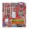
Thank you for choosing the G965M/ Q965M/ Q963M Series (MS-7241 v1.X) Micro-ATX mainboard. The G965M/ Q965M/ Q963M Series mainboards are based on Intel® G965/ Q965/ Q963 & ICH8/ ICH8R chipsets for optimal system efficiency. Designed to fit the advanced Intel® CoreTM 2 Duo, Pentium 4, Pentium D and - MSI G965M-FI | User Guide - Page 12
MS-7241 Mainboard Mainboard Specifications Processor Support - Intel® CoreTM 2 Duo, Pentium 4, Pentium D and Celeron D processors in the LGA775 package. For the latest information about CPU, please visit http://www.msi. c om . t w / progr am / prod uc t s/ m ai nboard/ m bd/ pro_ m bd_c pu _support - MSI G965M-FI | User Guide - Page 13
USB 2.0 pinheaders (JUSB1 is optional) - 1 CD-IN pinheader - 1 SPDIF-out pinheader (optional) Slots - 1 PCI Express x16 slot (for G965M/ Q965M series) - 1 PCI Express x1 slot - 2 PCI slots, support 3.3V/ 5V PCI bus Interface. Form Factor - Micro-ATX (24.4cm X 24.4cm) Mounting - 8 mounting holes 1-3 - MSI G965M-FI | User Guide - Page 14
E1 I nte l G965,Q965, Q963 R TL8110 SB / 810 0C/ 8110S C PCI E2 PCI 1 BATT + Int e l ICH8/ ICH8R (optional) JMicron Jm20335 JBAT1 ALC883/ ALC888 PCI 2 J AU D 1 CD_IN1 JSPD1 PWRFAN1 JUSB1 JUSB2 JU SB 3 SATA5 SATA3 SATA1 JCOM 1 SATA6 SATA4 SATA2 G965M/ Q965M/ Q963M Series (MS-7241 v1 - MSI G965M-FI | User Guide - Page 15
Packing Checklist Getting Started MSI motherboard MSI Driver/Utility CD SATA Cable (Optional) Power Cable Standard Cable for IDE Devices Back IO Shield User's Guide * The pictures are for reference only. Your packing contents may vary depending on the model you purchased. 1-5 - MSI G965M-FI | User Guide - Page 16
Hardware Setup Chapter 2 Hardware Setup This chapter provides you with the information about hardware setup procedures. While doing the installation, be careful in holding the components and follow the installation procedures. For some components, if you install in the wrong orientation, the - MSI G965M-FI | User Guide - Page 17
MS-7241 Mainboard Quick Components Guide CPUFAN1, p.2-14 SYSFAN1, p.2-14 CPU, p.2-3 DDRII DIMMs, p.2-7 JPW1, p.2-9 JCASE1, p.2-14 Back Panel, p.2-10 FDD1, p.2-12 IDE1, p.2-12 PCIE x16 Slot, p.2-19 PCIE x1 Slot, p.2-19 PCI Slots, p.2-19 PWRFAN1, p.2-14 - MSI G965M-FI | User Guide - Page 18
Central Processing Unit) This mainboard supports Intel® CoreTM 2 Duo, Pentium 4, Pentium D, Celeron D processor in LGA 775 package. W hen you are installing the CPU, make sure to install the cooler to prevent overheating. If you do not have the CPU cooler, contact your dealer to purchase and install - MSI G965M-FI | User Guide - Page 19
MS-7241 Mainboard CPU & Cooler Installation W hen you are installing the CPU, make sure the CPU has a cooler attached on the top to prevent not forget to apply some silicon heat transfer compound on CPU before installing the heat sink/ cooler fan for better heat dispersion. Follow the steps below to - MSI G965M-FI | User Guide - Page 20
the socket housing frame. Be sure to grasp on the edge of the CPU base. Note that the alignment keys are matched. alignment key 7. Visually inspect if the CPU is seated well into the socket. If not, take out the CPU with pure vertical motion and reinstall. 8. Cover the load plate onto the - MSI G965M-FI | User Guide - Page 21
MS-7241 Mainboard 9. Press down the load lever lightly onto the load plate, and switch Important 1. Check the information in H/W M onitor in BIOS (Chapter 3) for the CPU temperature. 2. Whenever CPU is not installed, always protect your CPU socket pin with the plastic cap covered (shown in Figure - MSI G965M-FI | User Guide - Page 22
Memory The mainboard provides four 240-pin non-ECC DDRII 800/ 667/ 533 DIMM slots. For more information on compatible components, please visit http://www.msi.com.tw/ p ro gr a m/ pr o du c t s /m ain bo ar d /m bd / pr o_ m bd _t r p_ lis t. ph p DDRII 240-pin, 1.8V 64x2=128 pin 56x2 - MSI G965M-FI | User Guide - Page 23
MS-7241 Mainboard Installing DDRII Modules 1. The memory module has only one notch on the center and will only fit in the right orientation. 2. Insert the memory - MSI G965M-FI | User Guide - Page 24
11 +12V 12 +3.3V 23 +5V 24 GND ATX 12V Power Connector: JPW1 This 12V power connector is used to provide power to the CPU. JPW1 2 1 4 3 Pin Definition PIN SIGNAL 1 GND 2 GND 3 12V 4 12V pin 13 pin 12 Important 1. Maker sure that all the connectors are connected to proper - MSI G965M-FI | User Guide - Page 25
MS-7241 Mainboard Back Panel Mouse Parallel Port IEEE1394 Port (optional) LAN L-In a PS/2® mouse/keyboard. Parallel Port Connector A parallel port is a standard printer port that supports Enhanced Parallel Port (EPP) and Extended Capabilities Parallel Port (ECP) mode. Serial Port Connector The - MSI G965M-FI | User Guide - Page 26
Hardware Setup USB Connectors The OHCI (Open Host Controller Interface) Universal Serial Bus root is for attaching USB devices such as keyboard, mouse, or other USB-compatible devices. Audio Port Connectors These audio connectors are used for audio devices. You can differentiate the color of the - MSI G965M-FI | User Guide - Page 27
MS-7241 Mainboard Connectors Floppy Disk Drive Connector: FDD1 This standard FDD connector supports 360K, 720K, 1.2M, 1.44M and 2.88M floppy disk types. FDD1 Hard Disk Connector: IDE1 (optional) The mainboard provides a USB to IDE connector that supports Ultra DMA 66/ 100 function. You can connect - MSI G965M-FI | User Guide - Page 28
Hardware Setup Serial ATA Connectors: SATA1~SATA6 SATA1~SATA6 are high-speed Serial ATA interface ports. Each supports 2nd generation serial ATA data rates of 300MB/s and is fully compliant with Serial ATA 2.0 specifications. Each Serial ATA connector can connect to 1 hard disk - MSI G965M-FI | User Guide - Page 29
MS-7241 Mainboard Fan Power Connectors: CPUFAN1, SYSFAN1 & PWRFAN1 The fan power connectors support Please refer to the recommended CPU fans at Intel® official website or consult the vendors for proper CPU cooling fan. CD-In Connector BIOS utility and clear the record. CINTRU 1 JCASE1 GND 2-14 - MSI G965M-FI | User Guide - Page 30
and is compliant with Intel® Front Panel I/O Connectivity Design Guide. 2 10 1 9 JAUD1 Pin Definition PIN SIGNAL DESCRIPTION 1 PORT 1L Analog Port 1 - Left channel 2 GND Ground 3 PORT 1R Analog Port 1 - Right channel 4 PRESENCE# Active low signal - signals BIOS - MSI G965M-FI | User Guide - Page 31
MS-7241 Mainboard Front Panel Connectors: JFP1/JFP2 The mainboard provides two front panel connectors for electrical connection to the front panel switches and LEDs. The JFP1 is compliant with Intel® Front Panel I/O Connectivity Design Guide. JFP1 1 HDD + LED Reset Switch + 9 2 Power LED + Power - MSI G965M-FI | User Guide - Page 32
, JUSB2, JUSB3 (JUSB1 is optional) The mainboard provides USB 2.0 pinheaders (optional USB 2.0 bracket available) that are compliant with Intel® I/O Connectivity Design Guide. USB 2.0 technology increases data transfer rate up to a maximum throughput of 480Mbps, which is 40 times faster than USB - MSI G965M-FI | User Guide - Page 33
MS-7241 Mainboard Jumpers Clear CMOS Jumper: JBAT1 There is a CMOS RAM onboard that has a power supply from external battery to keep the data of system configuration. - MSI G965M-FI | User Guide - Page 34
of 4.0 GB/s over a PCI Express x16 lane for graphics controllers, while PCI Express x1 supports transfer rate of 250 MB/s. PCI Express x16 Slot PCI Express x1 Slot PCI (Peripheral Component Interconnect software settings for the expansion card, such as jumpers, switches or BIOS configuration. 2-19 - MSI G965M-FI | User Guide - Page 35
MS-7241 Mainboard PCI Interrupt Request Routing The IRQ, acronym of interrupt request line and pronounced I-R-Q, are hardware lines over which devices can send interrupt signals to - MSI G965M-FI | User Guide - Page 36
This chapter provides information on the BIOS Setup program and allows you to configure the system for optimum use. You may need to run the Setup program when: ² An error message appears - MSI G965M-FI | User Guide - Page 37
MS-7241 under each BIOS category described in this chapter are under continuous update for BIOS maker as A = AMI, W = AWARD, and P = PHOENIX. 2nd - 5th digit refers to the model number. 6th digit refers to the chipset as I = Intel, N = nVidia, and V = VIA. 7th - 8th digit refers to the customer as MS - MSI G965M-FI | User Guide - Page 38
BIOS Setup Control Keys Enter> Move to sub-menu. If you want to return to the main menu, just press the . General Help The BIOS setup program provides a General Help screen. You can call up this screen from any menu by simply pressing . The - MSI G965M-FI | User Guide - Page 39
MS-7241 Mainboard The Main Menu Standard CMOS Features Use this menu for basic system configurations, such as time, date etc. Advanced BIOS Features Use for power management. PNP/PCI Configurations This entry appears if your system supports PnP/PCI. H/W Monitor This entry shows your PC health status. - MSI G965M-FI | User Guide - Page 40
BIOS Setting Password Use this menu to set the password for BIOS. Save & Exit Setup Save changes to CMOS and exit setup. Exit Without Saving Abandon all changes and exit setup. BIOS Setup 3-5 - MSI G965M-FI | User Guide - Page 41
MS-7241 Mainboard Standard CMOS Features The items in Standard CMOS Features Menu includes The format is . day Day of the week, from Sun to Sat, determined by BIOS. Read-only. month The month from Jan. through Dec. date The date from 1 to 31 can be keyed by numeric - MSI G965M-FI | User Guide - Page 42
BIOS Setup Device/ Vender/ Size It will showing the device information that you connected to the IDE/SATA connector . LBA/Large M ode This allows you to enable or disable the LBA Mode. Setting to Auto enables LBA mode if the device supports it and the devices is not already formatted with LBA mode - MSI G965M-FI | User Guide - Page 43
MS-7241 Mainboard System Information Press to enter the sub-menu, and the following screen appears. This sub-menu shows the CPU information, BIOS version and memory status of your system (read only). 3-8 - MSI G965M-FI | User Guide - Page 44
hen enabled, the BIOS data cannot be changed when attempting to update the BIOS with a Flash utility. To successfully update the BIOS, you will need inside the processor as two logical processors that can execute instructions simultaneously. In this way, the system performance is highly improved. If - MSI G965M-FI | User Guide - Page 45
MS-7241 Mainboard the processor will use only one core to execute the instructions. Please disable this item if your operating system doesn't support * CPU: An Intel® Pentium® 4 Processor with HT Technology; * Chipset: An Intel® Chipset that supports HT Technology; * BIOS: A BIOS that supports HT - MSI G965M-FI | User Guide - Page 46
Advanced Chipset Features BIOS Setup DRAM Frequency Setting to Auto, the system will auto detect the memory clock. Or use this item to configure the clock frequency of the - MSI G965M-FI | User Guide - Page 47
MS-7241 Mainboard DVMT/ FIXED M emory The field specifies the size of system memory allocated for video memory. "Fixed" mode is non-contiguous pagelocked memory allocated during driver initialization to provide a static amount of memory."DVMT" mode is memory that is dynamically allocated based on - MSI G965M-FI | User Guide - Page 48
you to enable/disable the onboard USB controller. USB Device Legacy Support Select [Enabled] if you need to use a USB-interfaced device in the operating system. USB 2.0 Controller Mode This setting allows you to select the USB controller mode. BIOS EHCI Hand-Off This item can used to stop the EHCI - MSI G965M-FI | User Guide - Page 49
MS-7241 Mainboard SATA Device Configuration Press to enter the sub-menu and IRQ14/ 15 for SATA devic es [Enhanced] Select Enhanced if you want to use the SATA as IDE / RAID or AHCI function Configure SATA#1 as W hen the SATA#1 Configuration sets to [Enhanced], the field is adjustable. - MSI G965M-FI | User Guide - Page 50
BIOS Setup Onboard Floppy Controller Select [Enabled] if your system has a floppy disk operate in ECP mode only. Choosing [ECP + EPP] will allow the onboard parallel port to support both the ECP and EPP modes simultaneously. Parallel Port IRQ This item allows you to set parallel port IRQ. - MSI G965M-FI | User Guide - Page 51
MS-7241 Mainboard Power Management Setup Important S3-related functions described in this section are available only when your BIOS supports mode is a low power state. In this state, no system context is lost (CPU or chipset) and hardware main- tains all system context. [S3/STR] The S3 sleep - MSI G965M-FI | User Guide - Page 52
Yes] allows BIOS to call VGABIOS driver of the card does not support the initialization feature, the display may work abnormally or not function after resuming from S3. Suspend Time Out (Minute) If system activity is not detected for the length of time specified in this field, all devices except CPU - MSI G965M-FI | User Guide - Page 53
MS-7241 Mainboard S3 Power On by PS/2 M ouse This setting determines whether the system will be awakened from S3 when input signal of the PS/2 mouse - MSI G965M-FI | User Guide - Page 54
BIOS Setup PNP/PCI Configurations This section describes configuring the PCI bus system and PnP (Plug & Play) feature. PCI, or Peripheral Component Interconnect, is a system which allows I/O devices to operate at speeds nearing the speed the CPU ) is where the BIOS stores resource information for - MSI G965M-FI | User Guide - Page 55
MS-7241 of available IRQs passed to devices that are configurable by the system BIOS. The available IRQ pool is determined by reading the ESCD NVRAM. operating system is ready, the system will interrupt itself and perform the service required by the I/O device. DM A Resource Setup Press - MSI G965M-FI | User Guide - Page 56
H/W Monitor BIOS Setup Chassis Intrusion The field enables or disables the feature set the field to [Reset]. The setting of the field will automatically return to [Enabled] later. CPU/ System Temperature, CPU/ SYSTEM FAN Speed, Vcore, 3VCC, +12.0V, VSB, VBAT These items display the current status - MSI G965M-FI | User Guide - Page 57
MS-7241 Mainboard Load Optimized Defaults The option on the main menu allows users to restore all of the BIOS settings to the default Optimized values. The Optimized Defaults are the default values set by the mainboard manufacturer specifically for optimal performance of the mainboard. W - MSI G965M-FI | User Guide - Page 58
BIOS Setup BIOS Setting Password W hen you select this function, a message as below will appear on the screen: Type the password, up to six characters in length, and - MSI G965M-FI | User Guide - Page 59
Realtek ALC883 Audio Appendix A Realtek ALC883 Audio The Realtek ALC883 provides 10-channel DAC that simultaneously supports 7.1 sound playback and 2 channels of independent stereo sound output (multiple streaming) through the Front-Out-Left and Front-OutRight channels. A-1 - MSI G965M-FI | User Guide - Page 60
MS-7241 Mainboard Installing the Realtek HD Audio Driver You need to install the driver for Realtek ALC883 codec to function properly before you can get access to 2-, 4-, 6-, 8- channel or 7.1+2 channel audio operations. Follow the procedures described below to install the drivers for different - MSI G965M-FI | User Guide - Page 61
Realtek ALC883 Audio 3. Click Next to install the Realtek High Definition Audio Driver. 4. Click Finish to restart the system. Click here Select this option Click here A-3 - MSI G965M-FI | User Guide - Page 62
MS-7241 Mainboard Software Configuration After installing the audio driver, you are able to use the 2-, 4-, 6- or 8- channel audio feature now Audio Configuration. It is also available to enable the audio driver by clicking the Azalia HD Sound Effect M anager from the Control Panel. Double click A-4 - MSI G965M-FI | User Guide - Page 63
Realtek ALC883 Audio Sound Effect Here you can select a sound effect you like from the Environment list. Environment Simulation You will be able to enjoy different sound experience by pulling down the arrow, totally 23 kinds of sound effect will be shown for selection. Realtek HD Audio Sound Manager - MSI G965M-FI | User Guide - Page 64
MS-7241 Mainboard Equalizer Selection Equalizer frees users from default settings; users may create their owned preferred settings by utilizing this tool. 10 bands of equalizer, ranging - MSI G965M-FI | User Guide - Page 65
Realtek ALC883 Audio Frequently Used Equalizer Setting Realtek recognizes the needs that you might have. By leveraging our long experience at audio field, Realtek HD Audio Sound Manager provides you certain optimized equalizer settings that are frequently used for your quick enjoyment. [How to Use - MSI G965M-FI | User Guide - Page 66
MS-7241 Mainboard Mixer In the Mixer part, you may adjust the volumes of the rear are well plugged in the jacks on the rear or front panel. 2. Multi-Stream Function ALC883 supports an outstanding feature called Multi-Stream, which means you may play different audio sources simultaneously and let - MSI G965M-FI | User Guide - Page 67
Realtek ALC883 Audio W hen you are playing the first audio source (for example: use W indows Media Player to play DVD/VCD), the output will be played from the rear panel, which is the default setting. Then you must to select the Realtek HD Audio 2nd output from the scroll list first, and use a - MSI G965M-FI | User Guide - Page 68
MS-7241 Mainboard 3. Playback control Tool Mute Playback device This function is to let you freely decide which ports to output the sound. And this is essential - MSI G965M-FI | User Guide - Page 69
4. Recording control Realtek ALC883 Audio Tool Mute Recording device -Realtek HD Digital input -Realtek HD Audio input Mute You may choose to mute single or multiple volume controls or to completely mute sound input. Tool - Show the following volume controls This is to let you freely decide - MSI G965M-FI | User Guide - Page 70
MS-7241 Mainboard Audio I/O In this tab, you can easily configure your multi-channel audio function and speakers. You can choose a desired jack changed to the one that is same as your device. - If not correct, Realtek HD Audio Manager will guide you to plug the device into the correct jack. A-12 - MSI G965M-FI | User Guide - Page 71
Connector Settings Click to access connector settings. Realtek ALC883 Audio Disable front panel jack detection (option) Jack detection function only works with HD audio front panel. Mute rear panel output when front headphone plugged in. Enable auto popup dialogue, when device has been plugged - MSI G965M-FI | User Guide - Page 72
MS-7241 Mainboard S/PDIF Short for Sony/Philips Digital Interface, a standard audio file transfer format. S/PDIF allows the transfer of digital audio signals from one device to - MSI G965M-FI | User Guide - Page 73
Realtek ALC883 Audio Test Speakers You can select the speaker by clicking it to test its functionality. The one you select will light up and make testing sound. If any speaker fails to make sound, then check whether the cable is inserted firmly to the connector or replace the bad speakers with - MSI G965M-FI | User Guide - Page 74
MS-7241 Mainboard Microphone In this tab you may set the function of the microphone. Select the Noise Suppression to remove the possible noise during recording, or - MSI G965M-FI | User Guide - Page 75
Realtek ALC883 Audio 3D Audio Demo In this tab you may adjust your 3D positional audio before playing 3D audio applications like gaming. You may also select different environment to choose the most suitable environment you like. A-17 - MSI G965M-FI | User Guide - Page 76
MS-7241 Mainboard Information In this tab it provides some information about this HD Audio Configuration utility, including Audio Driver Version, DirectX Version, Audio Controller & Audio Codec. You may also select the language of this utility by choosing from the Language list. Also there is a - MSI G965M-FI | User Guide - Page 77
Realtek ALC883 Audio Hardware Setup Connecting the Speakers W hen you have set the Multi-Channel Audio Function mode properly in the software utility, connect your speakers to the correct phone jacks in accordance with the setting in software utility. n 2-Channel Mode for Stereo-Speaker Output Refer - MSI G965M-FI | User Guide - Page 78
MS-7241 Mainboard n 4-Channel Mode for 4-Speaker Output Back Panel 1 4 2 5 3 6 4-Channel Analog Audio Output Description: Connect two speakers to back panel's front-channel Line Out connector and - MSI G965M-FI | User Guide - Page 79
Realtek ALC883 Audio n 6-Channel Mode for 6-Speaker Output Back Panel 1 4 2 5 3 6 6-Channel Analog Audio Output Description: Connect two speakers to back panel's Line Out connector, two speakers to the rear-channel Line out connector and two speakers to the center/ subwoofer-channel Line - MSI G965M-FI | User Guide - Page 80
MS-7241 Mainboard n 8-Channel Mode for 8-Speaker Output 1 4 2 5 3 6 8-Channel Analog Audio Output 1 Line In 2 Line Out (Front channels) 3 MIC 4 Line Out (Rear surround channels) 5 Line Out (Center - MSI G965M-FI | User Guide - Page 81
Intel ICH8R SATA RAID Appendix B Intel ICH8R SATA RAID The ICH8R (NH82801GR) provides a hybrid solution that combines six independent SATAII ports for support of up to six Serial ATAII (Serial ATAII RAID) drives. It offers RAID level 0 (Striping), RAID level 1 (Mirroring and Duplexing), RAID level 5 - MSI G965M-FI | User Guide - Page 82
MS-7241 Mainboard ICH8R Introduction The ICH8R provides a hybrid solution that combines 6 independent SATAII ports for support of up to 6 Serial ATAII (Serial ATAII RAID) drives. Serial ATAII (SATAII) is the latest generation of the ATA interface. SATA hard drives deliver blistering transfer speeds - MSI G965M-FI | User Guide - Page 83
should be integrated with the system BIOS on all motherboards with a supported Intel chipset. The Intel Matrix Stroage Manager Option ROM is the Intel RAID implementation and provides BIOS and DOS disk services. Please use + keys to enter the "Intel(R) RAID for Serial ATA" status screen - MSI G965M-FI | User Guide - Page 84
MS-7241 Mainboard After pressing the and keys simultaneously, the following window will appear: (1) Create RAID Volume 1. Select option 1 "Create RAID Volume" and press key. The following screen appears. Then in the Name field, specify a RAID Volume name and then press the - MSI G965M-FI | User Guide - Page 85
Intel ICH8R SATA RAID 3. In the Disk field, press key and the following screen appears. Use key to select the disks you want to create for the RAID volume, then click key to finish selection. 4. Then select the strip value for the RAID array by using the "upper arrow" or " - MSI G965M-FI | User Guide - Page 86
MS-7241 Mainboard Important Since you want to create two volumes (Intel Matrix RAID Technology), this default size (maximum) needs to be reduced for you to confirm if you are sure to create the RAID volume. Press to continue. 7. Then the following screen appears to indicate that the creation is - MSI G965M-FI | User Guide - Page 87
volume, but please be noted that all data on RAID drives will be lost. Important If your system currently boots to RAID and you delete the RAID volume in the Intel RAID Option ROM, your system will become unbootable. Select option 2 Delete RAID Volume from the main menu window and press key - MSI G965M-FI | User Guide - Page 88
MS-7241 Mainboard (3) Reset Disks to Non-RAID Select option 3 Reset Disks to Non-RAID and press to delete the RAID volume and remove any RAID structures from the drives. The following screen appears: Press key to accept the selection. Important 1. You will lose all data on the RAID - MSI G965M-FI | User Guide - Page 89
to specify an Additional Device(s). 3. Insert the driver diskette Intel IAA RAID Driver For ICH8R into drive A: and press . Important Please follow the instruction below to make an "Intel IAA RAID Driver For ICH8R (NH82801GR)" for yourself. 1. Insert the MSI CD into the CD-ROM drive. 2. Click - MSI G965M-FI | User Guide - Page 90
MS-7241 Mainboard Installation of Intel Matrix Storage Console The Intel Application Accelerator RAID Edition driver may be used to operate the hard drive from which the system is booting or a hard drive that contains important data. For this reason, you cannot remove or un-install this driver from - MSI G965M-FI | User Guide - Page 91
Intel ICH8R SATA RAID The InstallShield Wizard will begin automatically for installation showed as following: Click on the Next button to proceed the installation in the welcoming window. B-11 - MSI G965M-FI | User Guide - Page 92
MS-7241 Mainboard The window shows the components to be installed. Click Next button to continue. After reading the license agreement in the following window, click Yes button to continue. B B-12 - MSI G965M-FI | User Guide - Page 93
Intel ICH8R SATA RAID The following window appears to show the Readme File Information. It shows the system requirements and installation information. Once the installation is complete, the following window appears. B-13 - MSI G965M-FI | User Guide - Page 94
MS-7241 Mainboard RAID Migration Instructions The Intel Matrix Storage Console offers the flexibility to upgrade from a single Serial ATA (SATA) hard drive to RAID configuration when an additional SATA hard drive is added to the system. This process will create a new RAID volume from an existing - MSI G965M-FI | User Guide - Page 95
Intel ICH8R SATA RAID Create RAID Volume from Existing Disk To create a RAID volume from an existing disk, choose Action --> Create RAID Volume from Existing Hard Drive. The Create RAID Volume from Existing Hard Drive Wizard pops up to lead you for the following procedure. Click Next to continue. B- - MSI G965M-FI | User Guide - Page 96
MS-7241 Mainboard (1) Step 1: Configure Volume Here you can configure the new RAID volume by entering the volume name, selecting the RAID level and strip size. † RAID Volume Name: A desired RAID volume name needs to be typed in where the 'RAID_Volume1' text currently appears above. The RAID volume - MSI G965M-FI | User Guide - Page 97
system, this can be determined by making a note during POST of which port the single disk is attached to. You can also use the Intel Application Accelerator RAID Edition utility before the second disk is installed to verify the Port and serial number of the drive that contains all the data. B-17 - MSI G965M-FI | User Guide - Page 98
MS-7241 Mainboard (3) Select Member Hard Drive(s) Then select the member disk (the target disk) that you wish to use and then click "-->" to move it to - MSI G965M-FI | User Guide - Page 99
, if you do not specify 100% of the hard drive space, the rest hard drive space will be worked as RAID 1 volume, which is the new technology called Intel Matrix RAID. Then click Next to continue. (5) Start Creating RAID Volume from Existing Hard Drive Wizard Before you continue the procedure of - MSI G965M-FI | User Guide - Page 100
MS-7241 Mainboard (6) Start Migration The migration process may take up to two hours to complete depending on the size of the disks being used and the - MSI G965M-FI | User Guide - Page 101
system is powered off. 2. Replace the failed hard drive with a new one that is of equal or greater c ap ac i t y. 3. Reboot the system to Intel RAID Option ROM by press and keys simultaneously during the Power-On Self Test (POST). 4. Select the port of the destination disk for rebuilding - MSI G965M-FI | User Guide - Page 102
MS-7241 Mainboard 5. Exit Intel RAID Option ROM, and then reboot to W indows system. 6. W hen prompted to rebuild the RAID volume, click 'Yes'. 7. The Intel(R) Storage Utility will be launched. Right-click the new hard drive and select 'Rebuild to this Disk'. The 'Rebuild W izard' will be launched
-
 1
1 -
 2
2 -
 3
3 -
 4
4 -
 5
5 -
 6
6 -
 7
7 -
8
-
9
-
10
-
11
-
12
-
13
-
14
-
15
-
16
-
17
-
18
-
19
-
20
-
21
-
22
-
23
-
24
-
25
-
26
-
27
-
28
-
29
-
30
-
31
-
32
-
33
-
34
-
35
-
36
-
37
-
38
-
39
-
40
-
41
-
42
-
43
-
44
-
45
-
46
-
47
-
48
-
49
-
50
-
51
-
52
-
53
-
54
-
55
-
56
-
57
-
58
-
59
-
60
-
61
-
62
-
63
-
64
-
65
-
66
-
67
-
68
-
69
-
70
-
71
-
72
-
73
-
74
-
75
-
76
-
77
-
78
-
79
-
80
-
81
-
82
-
83
-
84
-
85
-
86
-
87
-
88
-
89
-
90
-
91
-
92
-
93
-
94
-
95
-
96
-
97
-
98
-
99
-
100
-
101
-
102
 |
 |

G965M/Q965M/Q963M Series
MS-7241 (V1.X) Mainboard
G52-72411X1