MSI K8N NEO4-F User Guide
MSI K8N NEO4-F - Motherboard - ATX Manual
 |
UPC - 816909007725
View all MSI K8N NEO4-F manuals
Add to My Manuals
Save this manual to your list of manuals |
MSI K8N NEO4-F manual content summary:
- MSI K8N NEO4-F | User Guide - Page 1
K8N Neo4 Series MS-7125 (v1.X) ATX Mainboard G52-M7125X4 i - MSI K8N NEO4-F | User Guide - Page 2
Manual Rev: 1.1 Release Date: January 2005 FCC-B Radio Frequency Interference Statement This equipment has been tested not installed and used in accordance with the instruction manual, VOIR LA NOTICE D'INSTALLATION AVANT DE RACCORDER AU RESEAU. Micro-Star International MS-7125 This device complies - MSI K8N NEO4-F | User Guide - Page 3
properties of their respective owners. AMD, Athlon™, Athlon™ XP, Thoroughbred™, and Duron™ are registered trademarks of AMD Corporation. Intel® and Pentium® and CardBus are registered trademarks of the Personal Computer Memory Card International Association. Revision History Revision V1.0 V1.1 - MSI K8N NEO4-F | User Guide - Page 4
guide, BIOS updates, driver updates, and other information: http://www.msi.com.tw & http://www.msi. com.tw/program/service/faq/faq/esc_faq_list.php † Contact our technical staff at: [email protected] Safety Instructions 1. Always read the safety instructions carefully. 2. Keep this User's Manual - MSI K8N NEO4-F | User Guide - Page 5
Layout 1-5 Packing Contents 1-6 Chapter 2. Hardware Setup 2-1 Quick Components Guide 2-2 Central Processing Unit: CPU 2-3 CPU Installation Procedures for Socket 939 2-4 Installing AMD Athlon64 CPU Cooler Set 2-5 Memory Jack 2-14 Audio Port Connectors ATA/Serial ATA RAID Connectors controlled - MSI K8N NEO4-F | User Guide - Page 6
BIOS Setup 3-1 Entering Setup ...3-2 Selecting the First Boot Device 3-2 Control Keys 3-3 Getting Help 3-3 The Main Menu ...3-4 Standard CMOS Features 3-6 Advanced BIOS Features 3-8 Advanced Chipset Features 3-11 Integrated Peripherals 3-12 Power Management Setup 3-17 PNP/PCI Configurations - MSI K8N NEO4-F | User Guide - Page 7
of RAID Configurations 5-2 RAID Configuration 5-3 Basic Configuration Instructions 5-3 Setting Up the NVRAID BIOS 5-3 NVIDIA RAID Untility Installation 5-7 Installing the RAID Driver (for bootable RAID Array 5-7 Installing the NVIDIA RAID Software Under W indows (for Non-bootable RAID Array - MSI K8N NEO4-F | User Guide - Page 8
viii - MSI K8N NEO4-F | User Guide - Page 9
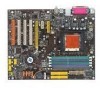
1. Getting Started Getting Started Thank you for choosing the K8N Neo4 series (MS-7125) v1. X ATX mainboard. The K8N Neo4 series mainboard is based the advanced AM D® K8 Athlon 64 FX / Athlon 64 processor, the K8N Neo4 series mainboard delivers a high performance and professional desktop platform solution. - MSI K8N NEO4-F | User Guide - Page 10
AMD Athlon 64/Athlon 64 FX CPU - HyperTransport supporting speed up to 1GHz (2000MT/s) - Supports PCI Express x16/x1/x2 interface - Two independent SATA controllers, for four drives - Dual Fast ATA-133 IDE controllers - IEEE802.3 nVIDIA MAC for 1000BASE-T Main Memory † Supports dual channel, eight - MSI K8N NEO4-F | User Guide - Page 11
1, 0+1, JBOD is supported - RAID function available for PATA+SATA H/D drives Gigabit LAN † Supports one LAN jacks - Supports 10/100/1000 Fast Ethernet by Marvell 88E1111 IEEE 1394 (Optional) † Supports up to two 1394 ports (rear panel x 1, pinheader x 1). Transfer rate is up to 400Mbps Audio † Chip - MSI K8N NEO4-F | User Guide - Page 12
the nVidia nForce4 system driver is only available for Windows 2000 and Windows XP. 2. To create a bootable RAID volume for a Windows 2000 environment, Microsoft's Windows 2000 Service Pack 4 (SP4) is required. As the end user cannot boot without SP4, a combination installation CD must be created - MSI K8N NEO4-F | User Guide - Page 13
Mainboard Layout Getting Started DIMM 1 DIMM 2 DIMM 3 DIMM 4 W inbo nd W 836 27 THF Top : mo use B otto m: key bo ard To p : Slot 1 J1394_1 ( O p tio n a l ) Codec PCI Slot 2 PCI Slot 3 PCI Slot 4 JAUD1 JCD1 JDB1 MSI C oreC ell BATT + N Fo rc e4 U ltra/ St an dard S ATA 2 S ATA 1 S ATA 4 - MSI K8N NEO4-F | User Guide - Page 14
S-7125 ATX M ainboard Packing Contents MSI motherboard MSI Driver/Utility CD SATA RAID Driver Diskette SATA Cable (Optional) Power Cable D-Bracket 2 (Optional) Round Cable of IDE Devices (Optional) Round Cable of Floppy Disk (Optional) 1394 Cable (Optional) Back IO Shield User's Guide 1-6 - MSI K8N NEO4-F | User Guide - Page 15
Hardware Setup Chapter 2. Hardware Setup Hardware Setup This chapter tells you how to install the CPU, memory modules, and expansion cards, as well as how to setup the jumpers on the mainboard. Also, it provides the instructions on connecting the peripheral devices, such as the mouse, keyboard, etc. - MSI K8N NEO4-F | User Guide - Page 16
M S-7125 ATX M ainboard Quick Components Guide Back Panel I/ O,(Optional) p.2-12 CPU, p.2-3 DDR DIMMs, p.2-7 JPW1, p.2-10 SFAN1, p.2-16 CPUFAN1, p.2-16 JCI1, p.2-7 ATX1, p.2-10 JIR1, p.2-20 FDD1, p.2-16 PCI_E3, p.2-26 PCI_E2, p.2-26 PCI_E1, p.2-26 J1394_1, p.2-21 (Optional) PCI - MSI K8N NEO4-F | User Guide - Page 17
Setup Central Processing Unit: CPU The mainboard supports AMD® Athlon64 processor. The mainboard uses a CPU socket called Socket-939 for easy CPU installation. W hen you are installing the CPU, make sure the CPU safety of CPU. Overclocking This motherboard is designed to support overclocking. However - MSI K8N NEO4-F | User Guide - Page 18
Open Lever 90 degree 3. Look for the gold arrow on the CPU. The gold arrow should point as shown in the picture. The CPU can only fit in the correct orientation.Lower the CPU down onto the socket. 4. If the CPU is correctly installed, the pins should be completely embedded into the socket and can - MSI K8N NEO4-F | User Guide - Page 19
Hardware Setup Installing AMD Athlon64 CPU Cooler Set W hen you are installing the CPU, make sure the CPU has a heat sink and a cooling fan attached on the top to prevent overheating. If you do not have the heat sink and cooling fan, contact your dealer to purchase and install them before turning - MSI K8N NEO4-F | User Guide - Page 20
Fix Lever, Safety Hook and the Fixed Bolt. Lift up the intensive fixed lever. Safety Hook 9. Attach the CPU Fan cable to the CPU fan connector on the mainboard. Fixed Lever Fixed Bolt MSI Reminds You... While disconnecting the Safety Hook from the fixed bolt, it is necessary to keep an eye on - MSI K8N NEO4-F | User Guide - Page 21
Setup Memory The mainboard provides 4 slots for 184-pin DDR SDRAM DIMM (Double In-Line Memory Module) modules and supports the memory size up to 4GB. You can install DDR266/ 333/400 modules on the DDR DIMM slots (DDR 1~4). For the updated supporting memory modules, please visit http://www.msi - MSI K8N NEO4-F | User Guide - Page 22
1GB System Density 256MB~2GB 256MB~2GB 512MB~4GB MSI Reminds You... - Dual-channel DDR works ONLY in the 3 combinations listed in the table as below. - Please select the identical memory modules to install on the dual channel, and DO NOT install three memory modules on three DIMMs, or it may cause - MSI K8N NEO4-F | User Guide - Page 23
Hardware Setup MSI Reminds You... 1. The maximum memory speed decreases when the following two Memory Combination is selected (you can also refer to the Recommended Memory Combination list shown in the previous page: - Each channel is installed with two double-sided memory mod- ules - Both DIMM1 and - MSI K8N NEO4-F | User Guide - Page 24
supports ATX power supply for the power system. Before inserting the power supply connector, always make sure that all components are installed used to provide power to the CPU. 3 4 1 2 JPW1 JPW1 Pin Definition PIN SIGNAL 1 GND 2 GND 3 12V 4 12V MSI Reminds You... 1. These two - MSI K8N NEO4-F | User Guide - Page 25
modules under S5 (power-off) states, and the power code is plugged while installing modules. Due to several pins are very sensitive to ESD, so this kind of memory-replacement actions might cause system chipset unable to boot. Please follow the following solution to avoid this situation. Unplug - MSI K8N NEO4-F | User Guide - Page 26
M S-7125 ATX M ainboard Back Panel The back panel provides the following connectors: Mouse Parallel LAN L-In RS-Out Keyboard COM Port 1394 Port SPDIF (Optional) Out (Coaxial) USB Ports L-Out CS-Out Mic SPDIF Out (Optical) Mouse Connector (Green) / Keyboard Connector (Purple) The mainboard - MSI K8N NEO4-F | User Guide - Page 27
Setup a wide range of devices, including consumer electronics audio/video (A/V) appliances, storage peripherals, other PCs, 5 VCC 6 -Data 1 7 +Data 1 8 GND DESCRIPTION +5V Negative Data Channel 0 Positive Data Channel 0 Ground +5V Negative Data Channel 1 Positive Data Channel 1 Ground 2-13 - MSI K8N NEO4-F | User Guide - Page 28
. Mic is a connector for microphones. However, there is an advanced audio application provided by Realtek ALC850 to offer support for 7.1-channel audio operation and can turn rear audio connectors from 2-channel to 4-/5.1-/7.1 channel audio. S/PDIF Out-Coaxial Line In ( in 7.1CH / 6CH) Line Out - MSI K8N NEO4-F | User Guide - Page 29
Hardware Setup Parallel Port Connector: LPT1 The mainboard provides a 25-pin female centronic connector as LPT. A parallel port is a standard printer port that supports Enhanced Parallel Port (EPP) and Extended Capabilities Parallel Port (ECP) mode. 13 1 25 14 Pin Definition PIN SIGNAL - MSI K8N NEO4-F | User Guide - Page 30
NBFAN1 MSI Reminds You... 1. Always consult the vendors for proper CPU cooling fan. 2. CPUFAN1 supports fan control. You can install Core Center util- ity that will automatically control the CPU fan speed according to the actual CPU temperature. 3. Please refer to the recommended CPU fans at AMD - MSI K8N NEO4-F | User Guide - Page 31
Master and a Slave drive. MSI Reminds You... If you install two hard disks on cable, you must configure the second drive to Slave mode by setting its jumper. Refer to the hard disk documentation supplied by hard disk vendors for jumper setting instructions. Chassis Intrusion Switch Connector: JCI1 - MSI K8N NEO4-F | User Guide - Page 32
serial ATA connectors SATA1~SATA4. SATA1~SATA4 support 1st generation serial ATA data rates of 150MB/s. Each Serial ATA connector can connect to 1 serial ATA device. Please refer to the nVidia RAID Introduction for detailed software installation procedure. SATA2 7 1 SATA1 SATA4 SATA1~ SATA4 Pin - MSI K8N NEO4-F | User Guide - Page 33
- JUSB1, JUSB2, JUSB3 (USB 2.0) Connected to JUSB1, JUSB2, or JUSB3 (the USB pinheader in YELLOW color) 5 USB0+ 7 GND 9 Key (no pin) 6 USB1+ 8 GND 10 USBOC USB 2.0 Bracket (Optional) MSI Reminds You... Note that the pins of VCC and GND must be connected correctly, or it may cause some - MSI K8N NEO4-F | User Guide - Page 34
future use to control headphone amplifier No pin Left channel audio signal to front panel Left channel audio signal return from front panel MSI Reminds You... If you don't want to connect to the front audio header, pins 5 & 6, 9 & 10 have to be jumpered in order to have signal output directed to - MSI K8N NEO4-F | User Guide - Page 35
Hardware Setup IEEE 1394 Connectors: J1394_1 (Optional) The mainboard provides another 1394 J1394_1 PIN SIGNAL PIN 1 TPA+ 2 3 Ground 4 5 TPB+ 6 7 Cable power 8 9 Key (no pin) 10 SIGNAL TPAGround TPBCable power Ground Connected to J1394 (the 1394 pinheader in GREEN color) - MSI K8N NEO4-F | User Guide - Page 36
a USB Bracket that supports both USB1.1 & 2.0 spec. It integrates four LEDs and allows users to identify system problem through 16 various combinations DBG4 (high for green color) 8 DBR4 (high for red color) 9 Key 10 NC Connected to JDB1 D-Bracket™ 2 (Optional) Connected to JUSB1, JUSB2 or JUSB3 - MSI K8N NEO4-F | User Guide - Page 37
Memory Detection Test Testing onboard memory size. The D-LED will hang if the memory module is damaged or not installed properly. Decompressing BIOS image to RAM for fast booting. Initializing Keyboard Controller. Testing VGA BIOS This will start writing VGA sign-on message to the screen - MSI K8N NEO4-F | User Guide - Page 38
Video Interface This will start detecting CPU clock, checking type of video onboard. Then, detect and initialize the video adapter. BIOS Sign On This will start showing information about logo, processor brand name, etc... Testing Base and Extended Memory Testing base memory from 240K to 640K and - MSI K8N NEO4-F | User Guide - Page 39
will explain how to change your motherboard's function through the use of button. Clear CMOS Button: SW1 There is a CMOS RAM on board that has a power supply from external battery to keep the system configuration data. W ith the CMOS RAM, the system can automatically boot OS every time it is turned - MSI K8N NEO4-F | User Guide - Page 40
, while PCI Express x1 supports transfer rate of 250 MB/s. PCI Express x16 slot PCI Express x1 slot PCI Express x4 slot (supports PCI-E x2 device only) hardware or software settings for the expansion card, such as jumpers, switches or BIOS configuration. The orange PCI slot (PCI4) also works as a - MSI K8N NEO4-F | User Guide - Page 41
Hardware Setup PCI Interrupt Request Routing The IRQ, acronym of interrupt request line and pronounced I-R-Q, are hardware lines over which devices can send interrupt signals to the - MSI K8N NEO4-F | User Guide - Page 42
BIOS Setup program and allows you to configure the system for optimum use. You may need to run the Setup program when: ” An error message appears on the screen during the system booting up, and requests you to run SETUP. ” You want to change the default settings for customized features. MSI Reminds - MSI K8N NEO4-F | User Guide - Page 43
MS-7125 ATX Mainboard Entering Setup Power on the computer and the system will start POST (Power On Self Test) process. When the message below appears on the screen, press key to enter Setup. Press DEL to enter SETUP If the message disappears before you respond and you still wish to enter - MSI K8N NEO4-F | User Guide - Page 44
to the main menu, just press the . General Help The BIOS setup program provides a General Help screen. You can call up this screen from any menu by simply pressing . The Help screen lists the appropriate keys to use and the possible selections for the highlighted item. Press to - MSI K8N NEO4-F | User Guide - Page 45
on the screen. The Main Menu allows you to select from twelve setup functions and two exit choices. Use arrow keys to select among the items and press to accept or enter the sub-menu. Standard CMOS Features Use this menu for basic system configurations, such as time, date etc. Advanced BIOS - MSI K8N NEO4-F | User Guide - Page 46
Optimized Defaults Use this menu to load the BIOS values for the best system performance, but the system stability may be affected. BIOS Setting Password Use this menu to set the password for BIOS. Save & Exit Setup Save changes to CMOS and exit setup. Exit Without Saving Abandon all changes and - MSI K8N NEO4-F | User Guide - Page 47
MS-7125 ATX Mainboard Standard CMOS Features The items in Standard CMOS Features Menu includes some basic setup items. Use the arrow keys to highlight the item and then use the or keys or listed, you can use [Manual] to define your own drive type manually. If you select [Manual], - MSI K8N NEO4-F | User Guide - Page 48
is detected at boot. Available options are: [All Errors] [No Errors] [All, But Keyboard] [All, But Diskette] [All, But Disk/Key] The system stops and the following screen appears: CPU Type/BIOS Version/System Memory/Total Memory The items show the CPU type, BIOS version and memory status of your - MSI K8N NEO4-F | User Guide - Page 49
to use, consult the vendor of your operating system. Settings: [1.4], [1.1]. Full Screen LOGO Display This item enables you to show the company logo on the bootup screen. Settings are: [Enabled] Shows a still image (logo) on the full screen at boot. [Disabled] Shows the POST messages at - MSI K8N NEO4-F | User Guide - Page 50
BIOS Setup Boot Sequence Press to enter the sub-menu and the following screen appears: 1st/2nd/3rd Boot Device The items allow you to set the sequence of boot devices where BIOS attempts to load the disk operating system. Boot Other Device Setting the option to [Enabled] allows the system to - MSI K8N NEO4-F | User Guide - Page 51
MS-7125 ATX Mainboard Advanced Chipset Features DRAM Configuration Press to enter the sub-menu and the following screen appears: Timing Mode This field has the capacity to automatically detect all of the DRAM timing. If you set this field to [Manual], the following fields will be selectable. - MSI K8N NEO4-F | User Guide - Page 52
DRAM is installed in the system. Available settings: [Auto], [2T], [3T], [4T], [5T], [6T], [7T]. Row cycle time (Trc) When the Timing Mode is set to [Manual], the field is adjustable. The row cycle time determines the minimum number of clock cycles a memory row takes to complete a full cycle, from - MSI K8N NEO4-F | User Guide - Page 53
another address higher than 00E0. (This item only activities in 64-bit OS) The settings are: [0000~00E0]. 1T/ 2T Memory Timing When the User Config mode is set to [Manual], the field is adjustable. This field controls the SDRAM command rate. Selecting [1T] makes SDRAM signal controller to run at 1T - MSI K8N NEO4-F | User Guide - Page 54
BIOS Setup Read Preamble value When the User Config mode is set to [Manual], the field is adjustable. [6ns], [7ns], [8ns], [9ns], [10ns], [11ns]. S/W memory hole Remapping This field enables software to remap the physical memory to the address higher than 00E0. (This item only activities in 64-bit - MSI K8N NEO4-F | User Guide - Page 55
MS-7125 ATX Mainboard Integrated Peripherals USB Controller This setting allows you to enable/disable the onboard USB controller. Selecting [V1.1+V2.0] enables the system to support both USB 1.1 and 2.0 spec. Setting options: [Disabled], [V1.1], [V1.1+V2.0]. USB KB/Storage Support Select [Enabled] - MSI K8N NEO4-F | User Guide - Page 56
controller cards to connect an audio device. The settings are: [Auto], [Disabled]. I/O Device Configuration Press to enter the sub-menu and the following screen appears: Onboard FDC Controller Select [Enabled] if your system has a floppy disk controller (FDD) installed on the system board - MSI K8N NEO4-F | User Guide - Page 57
MS-7125 ATX of IR transmission/reception. Setting options: [Full], [Half]. Under [Full] Duplex mode, synchronous, bi-directional transmission/ only. Choosing [ECP + EPP] will allow the onboard parallel port to support both the ECP and EPP modes simultaneously. Choose [Normal] to use Standard - MSI K8N NEO4-F | User Guide - Page 58
BIOS Setup EPP Mode Select The onboard parallel port is EPP Spec. compliant, so after the user chooses the onboard parallel port with the EPP function, the following message will be displayed on the screen: "EPP Mode Select." At this time either [EPP 1.7] spec or [EPP 1.9] spec can be chosen. ECP - MSI K8N NEO4-F | User Guide - Page 59
] IrDA-compliant Serial Infrared Port [ASKIR] Amplitude Shift Keyed Infrared Port SATA Devices Configuration Press to enter the sub-menu and the following screen appears: RAID Enabled This item is used to enable/disable the onchip RAID function. When you set to enable and the following - MSI K8N NEO4-F | User Guide - Page 60
BIOS Setup MSI Reminds You... S3-related functions described in this section are available only when your BIOS supports S3 sleep mode. ACPI Standby State This item specifies the power saving modes for ACPI function. If your operating system supports ACPI, such as Windows 98SE, Windows ME, Windows - MSI K8N NEO4-F | User Guide - Page 61
MS-7125 ATX Mainboard Power Button Function This feature sets the function of Settings: [Enabled], [Disabled]. Resume By RTC Alarm The field is used to enable or disable the feature of booting up the system on a scheduled time/date. Settings: [Enabled], [Disabled]. Date The field specifies the date - MSI K8N NEO4-F | User Guide - Page 62
Plug and Play BIOS has the capacity to automatically configure all of the boot and Plug and Play compatible devices. However, this capability means absolutely nothing unless you are using a Plug and Play operating system such as Windows® 95/98. If you set this field to [Manual], choose specific - MSI K8N NEO4-F | User Guide - Page 63
MS-7125 ATX Mainboard ** PCI Express relative items ** Maximum Payload Size This item allows you to set the PCI Express Maximum payload size per time . Settings: [4096], [128], [256], [512], [1024], [2048]. MSI the system will interrupt itself and perform the service required by the I/O device. 3-22 - MSI K8N NEO4-F | User Guide - Page 64
BIOS Setup H/W Monitor This section shows the status of your CPU, fan, overall system status, etc. Monitor [Disabled]. PC Health Status Press and the following sub-menu appears. Current System/CPU Temperature, System Fan/CPU Fan Speed, Vcore, +12.0V, +3.3V, +5.0V, Battery, +5VSB These items - MSI K8N NEO4-F | User Guide - Page 65
MS-7125 ATX Mainboard Cell Menu The items in Cell Menu includes some important settings of CPU, AGP, DRAM and overclocking functions. MSI Reminds You... Change these settings only if you are familiar with the chipset. Current CPU / DDR Clock These two items show the current clocks of CPU & DDR. Read - MSI K8N NEO4-F | User Guide - Page 66
of overclocking, increasing the CPU frequency by 7%. 5th level of overclocking, increasing the CPU frequency by 9%. 6th level of overclocking, increasing the CPU frequency by 11%. MSI Reminds You... Even though the Dynamic Overclocking Technology is more stable than manual overclocking, basically - MSI K8N NEO4-F | User Guide - Page 67
MS-7125 ATX Mainboard SATA Spread Spectrum This setting is used to enable or disable the SATA Spread Spectrum feature. Setting options: [Disabled], [Down Spread]. PCIE Spread Spectrum This setting is used to enable or disable the CPU Spread Spectrum feature. When overclocking the CPU, always set it - MSI K8N NEO4-F | User Guide - Page 68
: [Auto], [2.50V]~[2.85V]. NF4 Voltage NV4 voltage is adjustable in the field. Setting options are: [1.50V]~[1.85V]. MSI Reminds You... The settings shown in different color in CPU Voltage, Memory Voltage and NF4 Voltage help to verify if your setting is proper for your system. Gray: Default setting - MSI K8N NEO4-F | User Guide - Page 69
MS-7125 ATX Mainboard Optimized Defaults The two options on the main menu allow users to restore all of the BIOS settings to the default Optimized mainboard. The Fail-Safe Defaults are the default values set by the BIOS vendor for stable system performance. When you select Load Optimized Defaults, a - MSI K8N NEO4-F | User Guide - Page 70
BIOS Setup BIOS Setting Password When you select this function, a message as below will appear on the screen: Type the password, up to eight characters in length, and press . The password typed now will replace any previously set password from CMOS memory boot and you can enter Setup without - MSI K8N NEO4-F | User Guide - Page 71
activate the MSI well-known features, Live Update and Core Center, which makes it easier to update the BIOS/drivers online, and to monitor the system hard- ware status (CPU/Fan temperature and speed) or to overclock the CPU/ memory. Once you have your DigiCell installed (locate the setup source - MSI K8N NEO4-F | User Guide - Page 72
MS-712M5SAI TFXeaMtuarienboard Main Before using this utility, it is required to have all the integrated peripherals/cards (LAN card, Wireless LAN card, MegaStick... etc.) and all the necessary drivers (onboard LAN driver, audio driver, CoreCenter, Live Update... etc.) installed correctly. The icon - MSI K8N NEO4-F | User Guide - Page 73
You can take advantage of Live Update to detect and update BIOS and drivers online. Core Center You can take advantage of Core Center to monitor the health status of your system and to overclock under Windows OS if your system supports overclocking function. MEGA STICK If you have your MEGA STICK - MSI K8N NEO4-F | User Guide - Page 74
In the H/W Diagnostic sub-menu, you can see the information, status and note of each DigiCell. You may double check the connection and installation of the item marked as gray. You may also click on the Mail to MSI button to send your questions or suggestions to MSI's technical support staff. 4-4 - MSI K8N NEO4-F | User Guide - Page 75
the status of all the LAN / WLAN / Bluetooth on the screen if the hardware is installed. The first icon indicates the onboard LAN on your system, the second icon indicates the wireless connection. You may click this icon to configure the advanced settings in the WLAN Card Mode dialogue box (see the - MSI K8N NEO4-F | User Guide - Page 76
settings are configured for your usage. The default software access point mode is set to WLAN Card Mode. For more advanced security settings and channels switching, . When building the network, you can set up 4 sets of WEP keys, which can be 5 characters (10 hex-adecimal digital) or 13 characters - MSI K8N NEO4-F | User Guide - Page 77
In this case you don't have toenable this function. SSID Means Service Set Identifier, a unique name shared among all points in a wireless channel in Infrastructure mode, which should be set to an available one (ex: with less traffic to ensure the stable and better connection). Associated Client List - MSI K8N NEO4-F | User Guide - Page 78
, or click "Refresh" button to update the available WLAN connections. If the network you are selecting is encrypted (WEP shown in the Encryption column), the screen will display as below. You need to enter the correct WEP key defined by AP in the specified WEP Key 1~4 fields to make the connection - MSI K8N NEO4-F | User Guide - Page 79
for the correct BIOS/driver version throughout the whole Web site. To use the function, you need to install the "MSI Live Update 3" application. After the installation, the "MSI Live Update 3" icon (as shown on the right) will appear on the screen. Double click the "MSI Live Update 3" icon, and the - MSI K8N NEO4-F | User Guide - Page 80
MS-712M5SAI TFXeaMtuarienboard MEGA STICK In the MEGA STICK sub-menu, you can configure the settings of MSI MEGA STICK and the media files (*.m3u, *.mp3, *.wav, *.cda, *.wma) on your system. Basic Function Here you can edit your own play list with the buttons "load", "save", "delete", "shuttle", " - MSI K8N NEO4-F | User Guide - Page 81
Introduction to DigiCell There is also a toolbar for you to execute some basic function, like play, stop, pause, previous/next song, song info and volume adjust. There is also a scroll bar on the top for you to forward/rewind. previous pause next forward/rewind bar stop play song's - MSI K8N NEO4-F | User Guide - Page 82
incorrectly. However, you can install the Supplemental Language Support provided by Microsoft to solve this problem. You need to have your Microsoft Setup CD prepared in the CD-ROM. The system will start to install the necessary components after the settings are configured here. Follow the steps - MSI K8N NEO4-F | User Guide - Page 83
the [Advanced] tab and select the language you want to be supported (the language of the filename in the MegaStick) from the dropdown list in the [Language for non-Unicode programs], then click [Apply]. The system will install the necessary components from your Microsoft Setup CD immediately. 4-13 - MSI K8N NEO4-F | User Guide - Page 84
MS-712M5SAI TFXeaMtuarienboard Core Center (for AMD K8 Processor) Click on the Core Center icon in the main menu and the Core Center program will be enabled. Cool'n'Quiet This utility provides a CPU open for users to overclock, overspec or to adjust the thresholds of system to send out the warning - MSI K8N NEO4-F | User Guide - Page 85
the system will automatically configure an optimal setting for you. MSI Reminds You... To ensure that Cool'n'Quiet function is activated and will be working properly, it is required to double confirm that: 1. Run BIOS Setup, and se- lect Cell Menu. Under Cell Menu, find Cool'n'Quiet Support, and set - MSI K8N NEO4-F | User Guide - Page 86
MS-712M5SAI TFXeaMtuarienboard Audio Speaker Setting In the Audio Speaker Setting sub-menu, you can configure the multi-channel audio operation, perform speaker test, and choose the environment you prefer while enjoying the music. You can scroll the bar of each equalizer to regulate the current - MSI K8N NEO4-F | User Guide - Page 87
test" button and the following dialogue box will appear: In this Speaker Configuration dialogue box, select the audio configuration which is identical to the audio jack on your mainboard. Once the correct audio configuration is selected, click "Apply" to save the changes. Then the following screen - MSI K8N NEO4-F | User Guide - Page 88
, you can configure setting of power-on, poweroff and restarting status. In the screen below, you can set the date, time, start-up programs respectively for power-on, power-off and restarting. Power On Here are the available settings for Power On function: Date Use the drop-down list to select - MSI K8N NEO4-F | User Guide - Page 89
Introduction to DigiCell Power Off / Restart You may configure the time (in the format hh:mm:ss) for , or you can right-click on the selected program and click Delete. delete the added program MSI Reminds You... You can also enable the Every turn on function, which will enable the specified program - MSI K8N NEO4-F | User Guide - Page 90
MS and you need to enter your user name & password everytime when you boot up your computer. 2. If there are multi users using the same computer It supports the following operating systems: Win9X, Windows ME, Windows 2000 & Windows XP. Default User Name It is only available for Windows 2000 & Windows - MSI K8N NEO4-F | User Guide - Page 91
businesses-to the common PC desktop. This technology uses multiple drives to either increase total disk space or to offer data protection. For all levels, RAID techniques optimize storage solutions by using multiple disks grouped together and treating them as a single storage resource. 5-1 - MSI K8N NEO4-F | User Guide - Page 92
MS-7125 ATX Mainboard Introduction System Requirement Operating System Support NVRAID supports the following operating systems: Windows XP Home Edition Windows XP Professional Edition Windows 2000 Professional RAID Arrays NVRAID supports the following types of RAID arrays described in this - MSI K8N NEO4-F | User Guide - Page 93
the desired RAID array. 3. Boot from the Windows CD, use the floppy disk that has the RAID driver to copy and install the nForce RAID software. (Check p.5-9 for details.) 4. Initialize the NVRAID Array Disks. Setting Up the NVRAID BIOS Be sure to enable the IDE RAID or SATA RAID items in RAID Config - MSI K8N NEO4-F | User Guide - Page 94
MS-7125 ATX Mainboard Understanding the "Define a New Array" Window Use the Define a New Array window to • Select the RAID Mode • Set up the Striping Block • Specify which disks to use for the RAID Array Depending on the platform used, the system can have one or more channels. In a typical system - MSI K8N NEO4-F | User Guide - Page 95
BIOS setup page appear in the Free Disks block. These are the drives that are available for use as RAID array disks. To designate a free disk to be used as a RAID array disk, 1. Tab to the Free Disks section. The first disk in the list is selected. 2. Move it from the Free Disks block to - MSI K8N NEO4-F | User Guide - Page 96
again to go back to the previous window and then press Ctrl-X to exit the RAID setup. Now that the RAID setup has been configured from the RAID BIOS, the next step is to configure and load NVRAID drivers under Windows, as explained in "Installing the NVIDIA RAID Software Under Windows" on p5-9. 5-6 - MSI K8N NEO4-F | User Guide - Page 97
nVIDIA RAID Introduction NVIDIA RAID Utility Installation Installing the RAID Driver (for bootable RAID Array) 1. After you complete the RAID BIOS setup, boot from the Windows CD, and the Windows Setup program starts. 2. Press F6 and wait for the Windows Setup screen to appear. 3. Specify the NVIDIA - MSI K8N NEO4-F | User Guide - Page 98
the floppy drive until the blue screen portion of Windows XP installation is completed, then take out the floppy. 5. Follow the instructions on how to install Windows XP. During the GUI portion of the install you might be prompted to click Yes to install the RAID driver. Click Yes as many times as - MSI K8N NEO4-F | User Guide - Page 99
upgrade the Windows IDE driver and install the RAID software. 1. Start the nForce Setup program to open the NVIDIA Windows nForce Drivers page. 2. Select the modules that you want to install. Make sure that the "NVIDIA IDE Driver" is selected. 3. Click Next and then follow the instructions. 4. After - MSI K8N NEO4-F | User Guide - Page 100
MS-7125 ATX Mainboard Initializing and Using the Disk Array The RAID array is now ready to be initialized under Windows. 1. Launch Computer Management by clicking . The Select Disks to Initialize window appears. The disks listed depend on how many arrays you have configured. 4. Click Next. The Select - MSI K8N NEO4-F | User Guide - Page 101
nVIDIA RAID Introduction 5. Check the disk in the list if you want to make the array a dynamic disk, then click Next. The Completing the Initialize and Convert Disk Wizard window appears. 6. Click Finish. The "Computer Management" window appears. The actual disks listed will depend on your system, - MSI K8N NEO4-F | User Guide - Page 102
nVidia\System\CK804\IDE\WinXP\raidtool or \\nVidia\System\CK804\ide\win2k\raidtool of the setup CD accompanied with your mainboard). The RAID configuration information appears in the right-side pane, as shown below. MSI Reminds You... The information in the figures in this part may very from what it - MSI K8N NEO4-F | User Guide - Page 103
nVIDIA RAID Introduction NVRAID Striped Array The figure below shows an example of a two hard drive striped array using identical 55.90 GB IDE hard drives (ST360015A), where one drive is configured as Master and the other drive is configured as Slave. The total disk space used is 111.80 GB. NVRAID - MSI K8N NEO4-F | User Guide - Page 104
, or not a part of any array, 1. Enter the system BIOS setup and make sure that the drive that you want to mark as free is RAID enabled. 2. Enter the RAID BIOS and make sure that the drive is not part of any array (if one exists). 3. Boot into Windows and run the NVRAIDMAN program. The drive appears - MSI K8N NEO4-F | User Guide - Page 105
the Disk as a Free Disk 1. Enter the system BIOS setup and make sure that the drive that you want to mark as free is RAID enabled. 2. Enter the RAID BIOS and make sure that the drive is not part of any array (if one exists). 3. Boot into Windows and run the NVRAIDMAN program. The drive appears under - MSI K8N NEO4-F | User Guide - Page 106
MS-7125 ATX Mainboard 3. Click Next. The RAID Array Selection page appears. 4. From the RAID Array Selection page, select one of the arrays from the list. This is the array to which you want to allocate the dedicated free disk. 5. Click Next. The Completing the NVIDIA Spare Disk Allocation page - MSI K8N NEO4-F | User Guide - Page 107
nVIDIA RAID Introduction Method 2: Select an array and then assign a free disk to it. 1. Right click on the array to The Free Disk Selection page appears. 4. From the Free Disk Selection page, select one of the disks from the list. Please note that there can be more than one disk to choose from. 5-17 - MSI K8N NEO4-F | User Guide - Page 108
MS-7125 ATX Mainboard 5. Click Next. The Completing the NVIDIA Spare Disk Allocation page appears. 6. Click Finish. You have now assigned a dedicated free disk to a mirrored - MSI K8N NEO4-F | User Guide - Page 109
. Then click Designate Spare to launch the Spare Disk Allocation Wizard. 2. Click Designate Spare and then follow the instructions in the Wizard. The figure below shows an example of a RAID 1 array that has one spare disk dedicated to it. Once a dedicated disk has been assigned to a particular array - MSI K8N NEO4-F | User Guide - Page 110
is synchronized between the two hard drives. This only applies to RAID 1 array as well as a RAID 0+1 array. Rebuilding Instructions After creating a mirrored array, you can rebuild the array using the following steps: 1. Go to Windows and run the NVRAID Management utility. The figure below shows an - MSI K8N NEO4-F | User Guide - Page 111
nVIDIA RAID Introduction 4. Click Next. The Disk Selection page appears. 5. Select the drive that you want to rebuild by clicking it from the list, then right corner of the screen as shown in the figure below. During the rebuilding process, the NVRAID Management utility screen shows the status under - MSI K8N NEO4-F | User Guide - Page 112
MS-7125 ATX Mainboard More About Rebuilding Arrays • Rebuilding Occurs in the Background The rebuilding process is very slow (it can take up to a day) and occurs in the background so as not to affect the performance of the system. • Rebuilding Applies Only to RAID 1 or RAID 0+1 Arrays Rebuilding an - MSI K8N NEO4-F | User Guide - Page 113
while utilizing full disk capacity. With SiIicon Image Serial ATA host controller and SATARAID5, both of these problems are solved. SATARAID5 software provides a Graphical User Interface (GUI) for easy-to-use configurations of the RAID Groups. MSI Reminds You... All the information/volumes listed in - MSI K8N NEO4-F | User Guide - Page 114
MS-7125 ATX Mainboard Introduction RAID - Redundant Array of Independent Disks RAID technology manages multiple disk drives to enhance I/O performance and provide redundancy in order to withstand the failure of any individual member, without loss of data. SATA RAID provides two RAID Set types, - MSI K8N NEO4-F | User Guide - Page 115
rotated from disk to disk. Parity RAID uses less capacity for protection and is the preferred method to reduce the cost per megabyte for larger installations. Mirroring requires 100% increase in capacity or a segment of a single disk drive. For home edition, JBOD function only supports one disk. 6-3 - MSI K8N NEO4-F | User Guide - Page 116
MS-7125 ATX Mainboard SATARAID5 Features h RAID 0, RAID 1, RAID 5, RAID 10, and JBOD Groups are supported. h Supported OS: Win2000/XP/Server 2003. h RAID Groups can be created and deleted without exiting Windows. h Hot Spare and On-line Rebuilding. The spare policy supports testing periodically for - MSI K8N NEO4-F | User Guide - Page 117
groups must be created and managed by the SATARAID5 GUI. During boot up, a screen similar to that below will appear for about 5 seconds. Press CTRL+S or the F4 key to enter the BIOS RAID utility. The RAID Utility menu screen will be displayed. A brief description of each section is presented on the - MSI K8N NEO4-F | User Guide - Page 118
of the drives physically attached to the SATA host adapter. Logical Drive Information This window displays all logical drives connected to the controller. The upper part lists RAID sets and JBOD drives reported to the system BIOS. The lower part lists spare drives, reserved drives, conflict drives - MSI K8N NEO4-F | User Guide - Page 119
Groups As previously discussed, the Silicon Image SATA host adapter supports RAID 0, 1, 5, 10, and JBOD configurations. The selection of the RAID level to be used should be based upon factors including performance, data security, and number of drives available. It is best to carefully consider the - MSI K8N NEO4-F | User Guide - Page 120
MS-7125 ATX Mainboard 4. If manual configuration is selected, the chunk size of Striped Sets can be selected. 5. If auto configuration is selected, BIOS will select RAID member drives automatically. 6. Select RAID set size with and keys. 7. After the RAID set size is set, the message "Are You Sure?" - MSI K8N NEO4-F | User Guide - Page 121
-RAID boot drive or data drive is desired, a JBOD can be created so BIOS will report it to the system BIOS. 1. To create a JBOD, Select "Create RAID set" 2. Select "JBOD" and press Enter. 3. Select JBOD drive from the physical drive list and press Enter. 4. Select JBOD size with and keys. 5. After - MSI K8N NEO4-F | User Guide - Page 122
set will be rebuilt. The status of the rebuild is displayed in the MAIN MENU window. Resolving Conflicts When a RAID set is created, the metadata written to the disk includes drive connection information including the channel on the host adapter to which it is connected. If after a disk failure the - MSI K8N NEO4-F | User Guide - Page 123
Silicon Image SATARAID5TM Introduction 2. Select the "Conflict" entry in the Logical Drive Status window and press Enter. 6-11 - MSI K8N NEO4-F | User Guide - Page 124
may need to be swapped, or in the case of a SATA-based removable drive unit, the order of the drives within the chassis made need to be changed. Press 'Y' to accept the change and resolve the conflict. 4. The conflict will be resolved. The RAID Set will appear in the Logical Drive window. 6-12 - MSI K8N NEO4-F | User Guide - Page 125
of the assignment of physical drives within a logical set (RAID set, RAID 1 spare, or unassigned). It is a display-only function. Use the up and down arrow keys to scroll between the drives in the Logical Drive Properties window. Press the ESC key when done viewing logical drive information. 6-13 - MSI K8N NEO4-F | User Guide - Page 126
a RAID set, spare drive, or JBOD, he or she has to select size for the set or drive. BIOS will set a default size for it and user can use the and keys to change the size. If the physical drive has never been used to create a set or drive by the BIOS before, the full - MSI K8N NEO4-F | User Guide - Page 127
of the drivers while installing Windows XP / 2000. 1. Start the installation: Boot from the CD-ROM. Press F6 when the message "Press F6 if you need to install third party SCSI or RAID driver" appears. 2. When the Windows XP/2000/Server 2003 Setup window is generated, press key to specify - MSI K8N NEO4-F | User Guide - Page 128
MS-7125 ATX Mainboard Installing Drivers and GUI Before installing the SATARAID5 software, Silicon Image Serial ATA host adapter driver must be installed. Insert MSI driver CD into the computer's CDROM drive and select Silicon Image SATA RAID Drivers. The Java 2 Runtime Environment is required for - MSI K8N NEO4-F | User Guide - Page 129
Silicon Image SATARAID5TM Introduction When a window appears asking for acceptance the license agreement, select I accept the terms of this license agreement and click Next. Choose the Typical setup type and click Next. When the installation completes, click Finish. Restart the computer when - MSI K8N NEO4-F | User Guide - Page 130
Installation of Drivers and Utility Chapter 6. Installation of Driver & Utility Installation of Drivers & Utility MSI provides a setup CD along with your mainboard, which contains the required drivers for your system, and many other useful and powerful utility to bring you the best experience for - MSI K8N NEO4-F | User Guide - Page 131
MS-7125 ATX Mainboard Driver Installation Click on the Driver tab and the screen below will display. Click on the driver you like to install, and follow the proceeding instructions. NVIDIA nForce4 System Driver This driver is only available for Windows 2000 and Windows XP operating system. Please - MSI K8N NEO4-F | User Guide - Page 132
. All the components shown here will be selected to be installed by default. Then click Next. 3. The system will start installing the selected driver components automatically. 4. Then the following screen displays the information for the NVIDIA IDE SW Driver installation. Click Next to continue. 7-3 - MSI K8N NEO4-F | User Guide - Page 133
from hacking. However, it is strongly suggested that you do not install this component. Please follow the instruction below to make a software firewall CD for yourself. 1. Insert the MSI CD into the CD-ROM drive. 2. Ignore the Setup screen and use "Explorer" to browse the CD. 3. In the \\nVidia - MSI K8N NEO4-F | User Guide - Page 134
and Utility Realtek AC97 Audio Driver 1. Click on this button to install the Realtek AC97 Audio Driver. Then the welcome dialogue will display. Click Next to continue. The installation process will launch automatically. 2. The following screen indicates the installation is complete. Click Yes - MSI K8N NEO4-F | User Guide - Page 135
MS-7125 ATX Mainboard Utility Installation Click on the Utility tab and the screen below will display. Click on the utility you like to install, and follow the proceeding instructions. 7-6
-
 1
1 -
 2
2 -
 3
3 -
 4
4 -
 5
5 -
 6
6 -
 7
7 -
8
-
9
-
10
-
11
-
12
-
13
-
14
-
15
-
16
-
17
-
18
-
19
-
20
-
21
-
22
-
23
-
24
-
25
-
26
-
27
-
28
-
29
-
30
-
31
-
32
-
33
-
34
-
35
-
36
-
37
-
38
-
39
-
40
-
41
-
42
-
43
-
44
-
45
-
46
-
47
-
48
-
49
-
50
-
51
-
52
-
53
-
54
-
55
-
56
-
57
-
58
-
59
-
60
-
61
-
62
-
63
-
64
-
65
-
66
-
67
-
68
-
69
-
70
-
71
-
72
-
73
-
74
-
75
-
76
-
77
-
78
-
79
-
80
-
81
-
82
-
83
-
84
-
85
-
86
-
87
-
88
-
89
-
90
-
91
-
92
-
93
-
94
-
95
-
96
-
97
-
98
-
99
-
100
-
101
-
102
-
103
-
104
-
105
-
106
-
107
-
108
-
109
-
110
-
111
-
112
-
113
-
114
-
115
-
116
-
117
-
118
-
119
-
120
-
121
-
122
-
123
-
124
-
125
-
126
-
127
-
128
-
129
-
130
-
131
-
132
-
133
-
134
-
135
 |
 |

MS-7125 (v1.X) ATX Mainboard
K8N Neo4 Series
G52-M7125X4