MSI K9N6SGM-V User Guide
MSI K9N6SGM-V - Motherboard - Micro ATX Manual
 |
UPC - 816909036312
View all MSI K9N6SGM-V manuals
Add to My Manuals
Save this manual to your list of manuals |
MSI K9N6SGM-V manual content summary:
- MSI K9N6SGM-V | User Guide - Page 1
if not installed and used in accordance with the instruction manual, may cause harmful interference to radio communications. However, VOIR LA NOTICE D'NSTALLATION AVANT DE RACCORDER AU RESEAU. Micro-Star International MS-7309 This device complies with Part 15 of the FCC Rules. Operation is subject - MSI K9N6SGM-V | User Guide - Page 2
trademark of Microsoft Corporation. Windows® 98/2000/NT/XP are registered trademarks of Microsoft Corporation. NVIDIA, the NVIDIA logo, DualNet, and nForce are registered trademarks or trademarks of NVIDIA Corporation in the United States and/or other countries. Netware® is a registered trademark of - MSI K9N6SGM-V | User Guide - Page 3
1. Always read the safety instructions carefully. 2. Keep this User Manual for future reference. 3. Keep this equipment away shock. 11. If any of the following situations arises, get the equipment checked by a service personnel: - The power cord or plug is damaged. - Liquid has penetrated into the - MSI K9N6SGM-V | User Guide - Page 4
sein de la communauté européenne. Par conséquent vous pouvez retourner localement ces matériels dans les points de collecte. MSI WEEE 2002/96/EC 13 2005 MSI MSI EC Español MSI como empresa comprometida con la protección del medio ambiente, recomienda: Bajo la directiva 2002/96/EC de la Uni - MSI K9N6SGM-V | User Guide - Page 5
mlü olacaktır. Avrupa Birliği'ne satılan MSI markalı ürünlerin kullanım süreleri bittiğinde MSI ürünlerin geri alınması isteği MAGYAR Annak érdekében, hogy környezetünket megvédjük, illetve környezetvédőként fellépve az MSI emlékezteti Önt, hogy ... Az Európai Unió („EU") 2005. augusztus 13-án hatá - MSI K9N6SGM-V | User Guide - Page 6
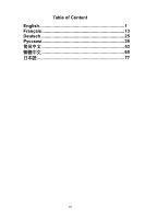
Table of Content English 1 Français 13 Deutsch 25 39 53 65 77 vi - MSI K9N6SGM-V | User Guide - Page 7
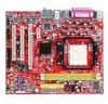
Introduction Thank you for choosing the K9N6GM series (MS-7309 v1.x) Micro-ATX mainboard. The K9N6GM series is design based on MCP(P)61 / MCP(S)61 / MCP(V)61 chipset for optimal system efficiency. Supports the AMD® Socket-AM2 processor, the K9N6GM series delivers a high performance and professional - MSI K9N6SGM-V | User Guide - Page 8
Specifications Processor Support • Supports Socket AM2 for AMD Sempron , Athlon 64 and Athlon 64 X2 (For the latest information about CPU, please visit http://www.msi.com.tw/program/products/mainboard/mbd/pro_mbd_cpu_support.php ) Chipset • nVIDIA MCP61(P) / MCP61(S) / MCP61(V) Memory Support • - MSI K9N6SGM-V | User Guide - Page 9
Intrusion Switch connector - 1 x Intel® Front Audio pin-head - 1 x CD-in connector - 1 x SPDIF-OUT connector Slots • 1 PCI Express x16 slot (K9N6PGM-FI/F) • 1 PCI Express x16 slot but only provides x8 bandwidth (K9N6SGM-V) • 1 PCI Express x1 slot • 2 PCI slots (support 3.3V/ 5V PCI bus Interface - MSI K9N6SGM-V | User Guide - Page 10
.msi.com.tw/program/products/mainboard/mbd/pro_mbd_cpu_support.php) Central Processing Unit: CPU The mainboard supports AMD® Athlon64 X2 / Athlon64 / Sempron processors. The mainboard uses a CPU socket called Socket AM2(940-pin) for easy CPU installation. CPU Installation Procedures for Socket AM2 - MSI K9N6SGM-V | User Guide - Page 11
This motherboard is designed to support overclocking. However, please make sure your components are able to tolerate such abnormal setting, while doing overclocking. Any attempt to operate beyond product specifications is not recommended. We do not guarantee the damages or risks caused by inadequate - MSI K9N6SGM-V | User Guide - Page 12
the socket. 3. The plastic clip at each side of the DIMM slot will automatically close. Power Supply The mainboard supports ATX used to provide power to the CPU. Floppy Disk Drive Connector: FDD1 The mainboard provides a standard floppy disk drive connector that supports 360K, 720K, 1.2M, 1.44M - MSI K9N6SGM-V | User Guide - Page 13
disk vendors for jumper setting instructions. Serial ATAII Connectors: SATA1~2 SATA 1, 2 are dual high-speed Serial ATA interface ports. Each supports 2nd generation serial ATA data rates of 300 MB/s. All connectors are fully compliant with Serial ATA 2.0 specifications. Each Serial ATAII connector - MSI K9N6SGM-V | User Guide - Page 14
audio and is compliant with Intel® Front Panel I/O Connectivity Design Guide. AUD_RET_R AUD_VCC Key (2)AUD_GND (1)AUD_MIC AUD_RET_L(10) AUD_FPOUT_L(9) AUD_MIC_BIAS HP_ON AUD_FPOUT_R MSI Jumper) to clear data. Follow the instructions below to clear the data: MSI Reminds You... You can clear CMOS - MSI K9N6SGM-V | User Guide - Page 15
transfers per second over a PCI Express x1 lane for Gigabit Ethernet, TV Tuners, 1394 controllers, and general purpose I/O. Also, desktop and expansion card graph functions, you have to enter the mainboard BIOS and select Advanced Chipset Features -> OnChip and PCIe VGA selection -> Both exist and - MSI K9N6SGM-V | User Guide - Page 16
BIOS Features Use this menu to setup the items of Award special enhanced features. Advanced Chipset Features Use this menu to change the values in the chipset This entry appears if your system supports PnP/PCI. H/W Monitor This entry shows the status of your CPU, fan, warning for overall system - MSI K9N6SGM-V | User Guide - Page 17
Password Use this menu to set BIOS setting Password. Save & Exit Setup Save changes to CMOS and exit setup. Exit Without Saving Abandon all changes and exit setup. Frequency/Voltage Current DRAM Clock It shows the current clock of memory. Read-only. Current CPU Clock It shows the current clock - MSI K9N6SGM-V | User Guide - Page 18
This setting is used to enable or disable the MCP61 PCIE Spread Spectrum feature. SATA Spread Spectrum This setting is used to enable or disable the SATA Spread Spectrum feature. MSI Reminds You... 1 .If you do not have any EMI problem, leave the setting at [Disabled] for optimal system stability - MSI K9N6SGM-V | User Guide - Page 19
érir une carte mère Micro-ATX des séries K9N6GM (MS-7309 v1.x). Les séries K9N6GM sont basées sur les chipsets MCP(P)61 / MCP(S)61 / MCP(V)61 pour obtenir un système performant. Destiné aux processeurs avancés AMD® AM2, les séries K9N6GM sont très performantes et offrent une solution adaptée tant - MSI K9N6SGM-V | User Guide - Page 20
Spécificités: CPU: • Supporte les processeurs AMD® Athlon 64/ Athlon X2 (Socket AM2). (Pour plus d' informations sur le CPU, veuillez visiter http://www.msi.com.tw/program/products/mainboard/mbd/pro_mbd_cpu_support.php) Chipset: • nVIDIA MCP61(P) / MCP61(S) / MCP61(V) Mémoire: • DDRII 533/ 667/ 800 - MSI K9N6SGM-V | User Guide - Page 21
USB (4 ports) 1 connecteur port de Front Panneau Audio 1 connecteur port de CD-in • 1 slot PCI Express x 16 (K9N6PGM-FI/F) • 1 slot PCI Express x 16, mais supporte seulement bandwidth x8 (K9N6SGM-V) • 1 slot PCI Express x 1 • 2 slots PCI, supporte l'interface de 3.3v/5v PCI bus. Format - MSI K9N6SGM-V | User Guide - Page 22
différents composants. Central Processing Unit: CPU La carte mère supporte les processeurs AMD® Athlon 64 / Athlon X2. Elle utilise un socket CPU appelé Socket AM2 (940 broches) pour l'installation. (Pour plus d' informations, veuillez visiter http://www.msi.com.tw/program/products/mainboard/mbd - MSI K9N6SGM-V | User Guide - Page 23
Cette carte mère a été créée pour supporter l'overclocking. veuillez s'assurer que vos composants tol du ventilateur du CPU au connecteur sur la carte. MSI Vous Rappelle... 1. Vérifiez la connexion du ventilateur de CPU avant de démarrer le PC. 2. Vérifiez les informations dans le BIOS PC Health - MSI K9N6SGM-V | User Guide - Page 24
à jour sur les modèles de mémoires supportés, veuillez visiter http://www.msi.com.tw/program/products/mainboard/mbd/pro_mbd_trp_list.php) d'alimentation ATX 12V: JPW1 Le connecteur d'alimentation 12V est utilisé pour alimenter le CPU. +3.3V +12V +12V 5VSB PWR OK GND +5V GND +5V GND +3.3V - MSI K9N6SGM-V | User Guide - Page 25
les instructions. Connecteurs Série ATA: SATA1/SATA2 Cette carte mère fournit deux ports d'une interface de Série ATA à grande vitesse. Ces ports supportent la caractéristiques si vous voulez contrôler le ventilateur du CPU. MSI Vous rappelle... Il faut toujours consulter votre revendeur au sujet - MSI K9N6SGM-V | User Guide - Page 26
Design (1)AUD_MIC Guide. AUD_MIC_BIAS HP_ON AUD_FPOUT_R AUD_RET_L(10) AUD_FPOUT_L(9) MSI Vous Rappelle... Si vous ne voulez pas connecter l'audio en façade pour effacer les données. Suivez les instructions de l'image pour effacer les données. MSI Vous Rappelle... Vous pouvez effacer les donné - MSI K9N6SGM-V | User Guide - Page 27
dent une large bande passante, supportent les PCI Express X16 Slot 2.5 Giga/s sur un PCI Express x1 pour Gigabit Ethernet, TV Tuners, contrôleurs 1394, et autre usage gré, vous devez entrer dans le bios de la carte mère et selectionner Advanced Chipset Features ->OnChip and PCIe VGA --> - MSI K9N6SGM-V | User Guide - Page 28
du BIOS tels que l'heure, etc. Advanced BIOS Features : Cette fonction permet de paramétrer des éléments avancés du BIOS. Advanced Chipset Features . PNP/PCI Configurations : Apparaît si votre système supporte PNP/PCI. H/W Monitor : Voir les statuts des CPU, du ventilateur, et de l'alarme du système. - MSI K9N6SGM-V | User Guide - Page 29
BIOS. Save & Exit Setup : Les modifications sont enregistrées dans le CMOS avant la sortie du setup. Exit Without Saving : Les modifications sont abandonnées avant la sortie du setup. Frequency/Voltage Control Current DRAM Clock: Vitesse d'horloge des DRAM. Lecture unique. Current CPU Manual, - MSI K9N6SGM-V | User Guide - Page 30
PCI hors service. En position [Enabled], le CPU/LDT Spread Spectrum: Cet élément est utilisé pour activer/ désactiver le CPU/LDT (HT Bus multiplier) Spread Spectrum. MCP61 MCP61 PCIE Spread Spectrum. SATA Spread Spectrum: Cet élément est utilisé pour activer/ désactiver leSATA Spread Spectrum. MSI - MSI K9N6SGM-V | User Guide - Page 31
Danke, dass Sie das K9N6GM (MS-7309 v1.x) Micro-ATX Mainboard gewählt haben. Das K9N6GM basiert auf dem MCP(P)61 / MCP(S)61 / MCP(V)61 Chipsatz und ermöglicht so ein optimales und effizientes System. Mit Unterstützung des AMD® Sockel-AM2 Prozessors, stellt das Mainboard K9N6GM die ideale Lösung zum - MSI K9N6SGM-V | User Guide - Page 32
besuchen Sie bitte http://www.msi.com.tw/program/products/mainboard/mbd/pro_mbd_trp_list.php ) LAN • Unterstützt 10/100 LAN mit Realtek 8201CL (K9N6SGM-V, K9N6VGM-V) • Unterstützt 10/100/1000 LAN mit Realtek 8211BL-GR (K9N6PGM-FI/F) Audio • 7.1-Kanal Audio Codec Realtek ALC888 (optional) • 7.1-Kanal - MSI K9N6SGM-V | User Guide - Page 33
zur CMOS-Löschung - 1 x Gehäusekontaktschalter - 1 x Intel® Front Audio Stiftleiste - 1 x CD-Eingang - 1 x SPDIF_Ausgang Stiftleiste Steckplätze • 1 PCI Express x16 Schnittstelle (K9N6PGM-FI/F) • 1 PCI Express x16 Schnittstelle mit x8 Bandbreite (K9N6SGM-V) • 1 PCI Express x1 Schnittstelle • 2 PCI - MSI K9N6SGM-V | User Guide - Page 34
einen CPU Sockel mit der Bezeichnung Sockel AM2(940-Pin). MSI weist darauf hin... Überhitzung Überhitzung beschädigt die CPU und das System nachhaltig, stellen Sie stets eine korrekte Funktionsweise des CPU Kühlers sicher, um die CPU vor Überhitzung zu schützen. Übertakten Dieses Motherboard wurde - MSI K9N6SGM-V | User Guide - Page 35
, dass die CPU richtig und vollständig im Sockel sitzt. MSI weist darauf hin... Überhitzung Überhitzung beschädigt die CPU und das System Sie zuerst den Netzstecker, um die Unversehrtheit Ihrer CPU zu gewährleisten Übertakten Dieses Motherboard wurde so entworfen, dass es Übertakten unterstützt - MSI K9N6SGM-V | User Guide - Page 36
Lüfters mit dem Anschluss auf dem Mainboard. MSI weist darauf hin... 1. Stellen Sie sicher, dass der CPU-Kühler richtig installiert ist befor Sie das System anschalten. 2. Prüfen Sie nach dem Einschalten die Anzeigen zur CPU-Temperatur in dem BIOS Bereich PC Health Status von H/W Monitor. Speicher - MSI K9N6SGM-V | User Guide - Page 37
3V ATX 12V Stromanschluss: JPW1 Dieser 12V Stromanschluss wird zur Stromversorgung der CPU benötigt. +12V GND +12V GND Anschluss des Diskettenlaufwerks: FDD1 das entsprechende Setzen einer Steckbrücke als Slave eingestellt werden. MSI weist darauf hin... Verbinden Sie zwei Laufwerke über ein - MSI K9N6SGM-V | User Guide - Page 38
öglicht den AUD_RET_R Anschluss von Audio-Ein- und -Ausgängen eines AUD_VCC Key Frontpanels. Der Anschluss entspricht den Richtlinien des Intel® Front Panel I/O Connectivity (2)AUD_GND (1)AUD_MIC Design Guide. AUD_MIC_BIAS HP_ON AUD_FPOUT_R AUD_RET_L(10) AUD_FPOUT_L(9) MSI weist darauf hin - MSI K9N6SGM-V | User Guide - Page 39
Sie hierfür JBAT1 (Clear CMOS Jumper - Steckbrücke zur CMOS Löschung). Befolgen Sie die Anweisungen in der Grafik, um die Daten zu löschen: MSI weist darauf hin... Sie können den CMOS löschen, indem Sie die Pins 2-3 verbinden, während das System ausgeschaltet ist. Kehren Sie danach zur Pinposition - MSI K9N6SGM-V | User Guide - Page 40
2,5 GB/Sekunde über eine PCI Express x1 Leitung für Gigabit- Lan, TV -Karten, IEEE1394 Controller anfängt. Zudem werden Desktop-Plattformen PCI-E)Grafikkarte nutzen wollen, müssen Sie in das Hauptplatinen BIOS gehen und unter Advanced Chipset Features -> OnChip and PCIe VGA selection -> Both exist - MSI K9N6SGM-V | User Guide - Page 41
nnen Sie die Basiskonfiguration Ihres Systems anpassen, so z.B. Uhrzeit, Datum usw. Advanced BIOS Features Verwenden Sie diesen Menüpunkt, um weitergehende Einstellungen an Ihrem System vorzunehmen. Advanced Chipset Features Verwenden Sie dieses Menü, um die Werte in den Chipsatzregistern zu ändern - MSI K9N6SGM-V | User Guide - Page 42
im CMOS und verlassen des BIOS. Exit Without Saving Verlassen des BIOS ohne Speicherung, vorgenommene Änderungen verfallen. Frequency/Voltage Current DRAM Clock Gibt den derzeitigen Takt des Speichers. Nur Anzeige. Current CPU Clock Gibt den derzeitigen Takt des CPU wieder. Nur Anzeige. Current FSB - MSI K9N6SGM-V | User Guide - Page 43
Wenn Sie es auf Manual einstellen, können Sie MCP61 PCIE Spread Spectrum Hier wird die Eigenschaft MCP61 PCIE Spread Spectrum ein- oder ausgeschaltet. SATA Spread Spectrum Hier wird die Eigenscahft SATA Spread Spectrum ein- oder ausgeschaltet. MSI weist darauf hin... 1. Sollten Sie keine Probleme - MSI K9N6SGM-V | User Guide - Page 44
Load Optimized Defaults Hier können Sie die BIOS- Voreinstellungen für den stabilen Betrieb laden, die der Mainboardhersteller vorgibt. 38 - MSI K9N6SGM-V | User Guide - Page 45
K9N6GM серии MS-7309 v1.x Micro ATX K9N6GM MCP(P)61 / MCP(S)61 / MCP(V)6 AMD® Socket-AM2 Top : mouse Bottom: keyboard JPW1 JCI1 JSPI1 Top : Parallel Port Bottom: COM 1 VGA port Top:1394(optional) Bottom: USB ports Top: LAN Jack Bottom: USB ports CPUFAN1 T:Line-In M:Line-Out B: - MSI K9N6SGM-V | User Guide - Page 46
Socket AM2 для AMD Sempron , Athlon 64 и Athlon 64 X2 http://www.msi.com.tw/program/products/mainboard/mbd/pro_mbd_cpu_support.php http://www.microstar.ru/program/products/mainboard/mbd/ pro_mbd_cpu_support.php nVIDIA MCP61(P) / MCP61(S) / MCP61(V DDRII 533/667/800 SDRAM (2 ГБ Max) • 2 - MSI K9N6SGM-V | User Guide - Page 47
USB - 1 x RJ-45 - 6 x - 2 x Front USB 4 порта) - 1 x CMOS - 1 x - 1 x Intel® Front Audio - 1 x CD-in - 1 x SPDIF-OUT Слоты • 1 PCI Express x16 слот (K9N6PGM-FI/F) • 1 PCI Express x16 x8 K9N6SGM-V) • 1 PCI Express x1 слот • 2 PCI 3.3V/ 5V PCI • Micro-ATX (24 - MSI K9N6SGM-V | User Guide - Page 48
Mouse Parallel Line ln RS 1394 port LAN (optional) Keyboard COM port VGA port USB ports Line Out CS MIC SS AMD® Athlon 64/ Athlon X2 Socket AM2 CPU http://www.msi.com.tw/program/products/mainboard/mbd/pro_mbd_cpu_support.php http://www.microstar.ru/program/products/ - MSI K9N6SGM-V | User Guide - Page 49
MSI CPU CPU 1 2 3 4 CPU 43 - MSI K9N6SGM-V | User Guide - Page 50
MSI 1 2 BIOS'a "PC Health Status H/W Monitor. Память 240 DDR II 533 / 667 / 800 SDRAM (DDR II 800 Athlon 64 X2 2 DIMM DIMM DDR II 1 2 3 300Вт. 24 ATX: - MSI K9N6SGM-V | User Guide - Page 51
PIO mode 0~4, Bus Master, и Ultra DMA 66/100 CD-ROM, 120 IDE1 Master и Slave Slave MSI Slave Serial ATAII SATA1~2 SATA 1, 2 Serial ATA Serial ATA 300 Serial ATA 2.0 Serial ATA 1 MSI serial ATA CD-In: JCD1 CD-ROM. R L GND JCI1 1 CINTRU 2 GND CPUFAN1/SYSFAN1 - MSI K9N6SGM-V | User Guide - Page 52
JFP1 2 8 1 7 Power LED JFP2 JAUD1 Intel® Front Panel I/O Connectivity Design Guide. AUD_RET_R AUD_VCC Key (2)AUD_GND (1)AUD_MIC AUD_RET_L(10) AUD_FPOUT_L(9) AUD_MIC_BIAS HP_ON AUD_FPOUT_R MSI 5 и 6, 9 и 10 Line-Out 2 10 1 9 IEEE 1394: J1394_1 IEEE 1394 IEEE - MSI K9N6SGM-V | User Guide - Page 53
Keep Data Clear Data MSI 2-3 CMOS 1 и 2 CMOS PCI Express Слот PCI Express PCI Express X16 Slot PCI Express PCI Express X1 Slot 2.5 PCI Express x1 канал) для Gigabit Ethernet 1394 PCI Express PCI-E BIOS Advanced Chipset Features ->OnChip and - MSI K9N6SGM-V | User Guide - Page 54
PCI (Peripheral Component Interconnect) PCI BIOS). PCI IRQ Interrupt ReQuest (line IRQ PCI INT A# ~ INT D# шины PCI Order1 Order2 Order3 Order4 PCI Slot 1 INT B# INT C# INT D# INT A# PCI Slot 2 INT C# INT D# INT A# INT B# 48 - MSI K9N6SGM-V | User Guide - Page 55
DEL>. DEL: Setup F11: Boot Menu TAB: Logo , и . Standard CMOS Features Advanced BIOS Features Advanced Chipset Features Integrated Peripherals Power Management Features PNP/PCI Configurations PnP/PCI. H/W Monitor Frequency/Voltage Control 49 - MSI K9N6SGM-V | User Guide - Page 56
Load Fail-Safe Defaults BIOS Load Optimized Defaults BIOS BIOS Setting Password Save & Exit Setup CMOS). Exit Without Saving Frequency/Voltage Current DRAM Clock Current CPU Clock Current FSB Multiplier Cool'n'Quiet AMD Adjust DDR2 Memory Frequency Auto SPD Limit 50 - MSI K9N6SGM-V | User Guide - Page 57
Manual SPD. Adjust DDR2 Voltage (V Auto Disable PCI Clock DIMM) и PCI Enabled PCI EMI). CPU/LDT Spread Spectrum CPU/LDT (HT Bus multiplier) Spread Spectrum. MCP61 PCIE Spread Spectrum MCP61 PCIE Spread Spectrum. SATA Spread Spectrum SATA Spread Spectrum. MSI 1 Disabled EMI Spread - MSI K9N6SGM-V | User Guide - Page 58
Load Optimized Defaults BIOS'a 52 - MSI K9N6SGM-V | User Guide - Page 59
简介 K9N6GM系列(MS-7309 v1.x) Micro-ATX主板. K9N6GM MCP(P)61 / MCP(S)61 / MCP(V)61 AMD® Socket-AM2 K9N6GM 布局 Top : mouse Bottom: keyboard JPW1 JCI1 JSPI1 Top : Parallel Port Bottom: COM 1 VGA port ATX1 SYSFAN1 Top:1394(optional) Bottom: USB ports Top: LAN Jack Bottom: USB ports CPUFAN1 - MSI K9N6SGM-V | User Guide - Page 60
规格 Socket AM2 接口的 AMD Sempron , Athlon 64 和 Athlon 64 X2 (要了解 CPU http://www.msi.com.tw/program/products/mainboard/mbd/pro_mbd_cpu_support.php nVIDIA MCP61(P) / MCP61(S) / MCP61(V DDRII 533/667/800 SDRAM (最高 2GB) • 2 DDRII DIMMs (240pin / 1.8V http://www.msi.com.tw/program/products/ - MSI K9N6SGM-V | User Guide - Page 61
USB 接口 - 1 个 RJ-45 接口 - 6 • 内部: - 2 个前置 USB 针头(4 个端口) - 1 个清除 CMOS 按钮 - 1 1 个Intel - 1 个 CD-in 接口 - 1 个 SPDIF-OUT 接口 插槽 • 1 条 PCI Express x16 插槽(K9N6PGM-FI/F) • 1 条 PCI Express x16 x8 带宽(K9N6SGM-V) • 1 条 PCI Express x1 插槽 • 2 条 PCI 3.3V/ 5V PCI 尺寸 • Micro-ATX (24.4cm X 20.5cm - MSI K9N6SGM-V | User Guide - Page 62
port LAN (optional) Keyboard COM port VGA port USB ports Line Out CS MIC SS 硬件安装 CPU CPU AMD® Athlon 64 / Athlon X2 Socket AM2,可简化CPU的安 装. (要了解 CPU http://www.msi.com.tw/program/products/mainboard/mbd/pro_mbd_cpu_support.php) Socket AM2 的CPU安装过程 1 2 90 度角. 3. 寻找CPU CPU - MSI K9N6SGM-V | User Guide - Page 63
CPU CPU CPU CPU CPU CPU CPU 1 座. 2 3 4. 将 CPU CPU 1 CPU 2. 在 BIOS PC CPU 的温度. 内存 2 条 240-pin DDR II 533 / 667 / 800 SDRAM DIMM 插槽(DDR II 800 is 仅对 于 Athlon 64 X2 1 1 条 DIMM DDRII 内存 Volt Notch 57 - MSI K9N6SGM-V | User Guide - Page 64
GND 20-pin ATX 20-pin ATX 电源适 +5V pin 1 和 pin 13 pin 11, 12, 23 和 24 GND +5V GND +3.3V +3.3V ATX 12V JPW1 此 12V CPU 供电. +12V +12V GND +5V +5V +5V Res GND GND GND PS-ON# GND -12V +3.3V GND GND FDD1 FDD,支持 360K, 720K, 1.2M, 1.44M 和 2.88M IDE - MSI K9N6SGM-V | User Guide - Page 65
GND 1 CINTRU 2 GND CPUFAN1/SYSFAN1 4-pin CPU_FAN 3-pin SYSFAN1 12V 12V GND. 如果您 GND +12V Sensor Control GND +12V Sensor CPU 风扇.. JFP1, JFP2 JFP1 是和 Intel 的 I/O 10 9 + -- + -+ Power Reset Switch Switch Power HDD LED LED 21 JFP1 Speaker 2 8 1 7 Power LED - MSI K9N6SGM-V | User Guide - Page 66
Giga,PCI Express x1 可 PCI Express X1 Slot 用与 Gigabit Ethernet, TV 转接卡, 1394 I/O PCI Express PCI Express PCI Express x16 APG8x 的 2 4.0 GB/,而 PCI Express x1 250 MB/s.. 注意: PCI-E VGA BIOS 并选择 Advanced Chipset Features -> OnChip and PCIe VGA selection -> Both exist and - MSI K9N6SGM-V | User Guide - Page 67
Setup F11: Boot Menu TAB: Logo Setup restart Ctrl>, 和 - MSI K9N6SGM-V | User Guide - Page 68
BIOS BIOS Setting Password(BIOS BIOS 的密码. Save & Exit Setup CMOS Setup 程序. Exit Without Saving CMOS Setup 程序. Current DRAM Clock(当前 DRAM Current CPU Clock(当前 CPU CPU Current FSB Multiplier(当前 FSB Cool'n'Quiet AMD CPU Adjust DDR2 Memory Frequency(调整 DDR2 Auto SPDs Limit Manual - MSI K9N6SGM-V | User Guide - Page 69
PCI CPU/LDT Spread Spectrum(CPU/LDT CPU/LDT (HT Bus multiplier MCP61 PCIE Spread Spectrum(MCP61 PCIE MCP61 PCIE SATA Spread Spectrum(SATA SATA u... 1 EMI Disabled EM Spread Spectrum EMI. 2. Spread Spectrum EMI Spread Spectrum EMI 规章. 3 Spread Spectrum 63 - MSI K9N6SGM-V | User Guide - Page 70
BIOS 64 - MSI K9N6SGM-V | User Guide - Page 71
簡介 K9N6GM系列(MS-7309 v1.x) Micro-ATX主機板. K9N6GM MCP(P)61 / MCP(S)61 / MCP(V)61 AMD® Socket-AM2 K9N6GM 配置 Top : mouse Bottom: keyboard JPW1 JCI1 JSPI1 Top : Parallel Port Bottom: COM 1 VGA port ATX1 SYSFAN1 Top:1394(optional) Bottom: USB ports Top: LAN Jack Bottom: USB ports CPUFAN1 - MSI K9N6SGM-V | User Guide - Page 72
規格 Socket AM2 介面的 AMD Sempron , Athlon 64 和 Athlon 64 X2 (要瞭解 CPU http://www.msi.com.tw/program/products/mainboard/mbd/pro_mbd_cpu_support.php nVIDIA MCP61(P) / MCP61(S) / MCP61(V DDRII 533/667/800 SDRAM (最高 2GB) • 2 DDRII DIMMs (240pin / 1.8V http://www.msi.com.tw/program/products/ - MSI K9N6SGM-V | User Guide - Page 73
USB 介面 - 1 個 RJ-45 介面 - 6 • 內部: - 2 個前置 USB 針頭(4 個埠) - 1 個清除 CMOS 按鈕 - 1 1 個Intel - 1 個 CD-in 介面 - 1 個 SPDIF-OUT 介面 插槽 • 1 條 PCI Express x16 插槽(K9N6PGM-FI/F) • 1 條 PCI Express x16 x8 帶寬(K9N6SGM-V) • 1 條 PCI Express x1 插槽 • 2 條 PCI 3.3V/ 5V PCI 尺寸 • Micro-ATX (24.4cm X 20.5cm - MSI K9N6SGM-V | User Guide - Page 74
port LAN (optional) Keyboard COM port VGA port USB ports Line Out CS MIC SS 硬體安裝 CPU CPU AMD® Athlon 64 / Athlon X2 Socket AM2,可簡化CPU 的安裝. (要瞭解 CPU http://www.msi.com.tw/program/products/mainboard/mbd/pro_mbd_cpu_support.php) Socket AM2 的CPU安裝過程 1 2 90 度角. 3. 尋找CPU CPU - MSI K9N6SGM-V | User Guide - Page 75
CPU CPU CPU CPU CPU CPU CPU 1 座. 2 3 4. 將 CPU CPU 1 CPU 2. 在 BIOS PC CPU 的溫度. 記憶體 2 條 240-pin DDR II 533 / 667 / 800 SDRAM DIMM 插槽(DDR II 800 is 僅 對於 Athlon 64 X2 1 1 條 DIMM DDRII 記憶體 Volt Notch 69 - MSI K9N6SGM-V | User Guide - Page 76
GND 20-pin ATX 20-pin ATX 電源供 +5V pin 1 和 pin 13 pin 11, 12, 23 和 24 GND +5V GND +3.3V +3.3V ATX 12V JPW1 此 12V CPU 供電. +12V +12V GND +5V +5V +5V Res GND GND GND PS-ON# GND -12V +3.3V GND GND FDD1 FDD,支援 360K, 720K, 1.2M, 1.44M 和 2.88M IDE - MSI K9N6SGM-V | User Guide - Page 77
GND 1 CINTRU 2 GND CPUFAN1/SYSFAN1 4-pin CPU_FAN 3-pin SYSFAN1 12V 12V GND. 如果您 GND +12V Sensor Control GND +12V Sensor CPU 風扇.. JFP1, JFP2 JFP1 是和 Intel 的 I/O 10 9 + -- + -+ Power Reset Switch Switch Power HDD LED LED 21 JFP1 Speaker 2 8 1 7 Power LED - MSI K9N6SGM-V | User Guide - Page 78
Giga,PCI Express x1 PCI Express X1 Slot 可用與 Gigabit Ethernet, TV 轉接卡, 1394 I/O PCI Express 結構的 PCI Express PCI Express x16 APG8x 的 2 4.0 GB/,而 PCI Express x1 250 MB/s.. 注意: PCI-E VGA BIOS 並選擇 Advanced Chipset Features -> OnChip and PCIe VGA selection -> Both exist and - MSI K9N6SGM-V | User Guide - Page 79
Setup F11: Boot Menu TAB: Logo Setup restart Ctrl>, 和 - MSI K9N6SGM-V | User Guide - Page 80
BIOS BIOS Setting Password(BIOS BIOS 的密碼. Save & Exit Setup CMOS Setup 程式. Exit Without Saving CMOS Setup 程式. Current DRAM Clock(當前 DRAM Current CPU Clock(當前 CPU CPU Current FSB Multiplier(當前 FSB Cool'n'Quiet AMD CPU Adjust DDR2 Memory Frequency(調整 DDR2 Auto SPDs Limit Manual - MSI K9N6SGM-V | User Guide - Page 81
PCI CPU/LDT Spread Spectrum(CPU/LDT CPU/LDT (HT Bus multiplier MCP61 PCIE Spread Spectrum(MCP61 PCIE MCP61 PCIE SATA Spread Spectrum(SATA SATA u... 1 EMI Disabled EM Spread Spectrum EMI. 2. Spread Spectrum EMI Spread Spectrum EMI 規章. 3 Spread Spectrum 75 - MSI K9N6SGM-V | User Guide - Page 82
BIOS 76 - MSI K9N6SGM-V | User Guide - Page 83
K9N6GM (MS-7309 v1.x) ATX K9N6GM MCP(P)61 / MCP(S)61 / MCP(V)61 AMD® Socket-AM2 K9N6GM Top : mouse Bottom: keyboard JPW1 JCI1 JSPI1 Top : Parallel Port Bottom: COM 1 VGA port ATX1 SYSFAN1 Top:1394(optional) Bottom: USB ports Top: LAN Jack Bottom: USB ports CPUFAN1 T:Line- - MSI K9N6SGM-V | User Guide - Page 84
AMD Socket AM2 による Sempron、Athlon 64 および Athlon 64 X2 CPU http://www.msi.com.tw/program/products/mainboard/mbd/pro_mbd_cpu_support.php nVIDIA MCP61(P) / MCP61(S) / MCP61(V DDRII 533/667/800 SDRAM (2GB Max) • 2 DDRII DIMMs (240 ピン / 1.8V http://www.msi.com.tw/program/products/mainboard/ - MSI K9N6SGM-V | User Guide - Page 85
- 1 x PS/2 1 x PS/2 1 x 1 x COM 1 x VGA 4 x USB 1 x RJ-45 6 x 2 x USB 4 1 x クリア CMOS 1 x 1 x Intel 1 x CD-in 1 x SPDIF-OUT 1 PCI Express x16 K9N6PGM-FI/F) • 1 PCI Express x16 8 K9N6SGM-V) • 1 PCI Express x1 2 PCI 3.3V/ 5V PCI Micro-ATX (24.4cm X 20.5cm 79 - MSI K9N6SGM-V | User Guide - Page 86
port LAN (optional) Keyboard COM port Hardware Setup VGA port USB ports Line Out CS MIC SS Central Processing Unit: CPU 本製品はAMD® Athlon 64 / Athlon X2 AM2 CPU CPU http://www.msi.com.tw/program/products/mainboard/mbd/pro_mbd_cpu_support.php) Socket AM2 CPU 1 い。 2 90 CPU Gold - MSI K9N6SGM-V | User Guide - Page 87
CPU CPU CPU CPU CPU CPU と CPU CPU 1 2 3 4. CPU MSI Reminds You... 1 CPU 2. BIOS には H/W Monitor の PC Health Status 中の CPU メモリ 2GB 240 2 DDR DDRII 533/ 667/ 800 SDRAM DDR II 800 は Athlon 64 X2 DIMM 81 - MSI K9N6SGM-V | User Guide - Page 88
電源 ATX 300W ATX 24 JWR1 ATX 電源 24 20 ピンの ATX 11/12/23/24 ATX 12V JPW1 +12V GND この 12V CPU 12V GND +3.3V +12V +12V 5VSB PWR OK GND +5V GND +5V GND +3.3V +3.3V GND +5V +5V +5V 66/100/133 Ultra DMA 66/100/133 4 CD-ROM, 120MB IDE1 HDD HDD MSI Reminds You 82 - MSI K9N6SGM-V | User Guide - Page 89
4 ピン CFAN1 と 3 ピン SFAN1 12V 12V GND GND +12V Sensor Control GND +12V Sensor MSI Reminds You JFP1, JFP2 LED JFP1はIntel® Front Panel I/O Connectivity Design Guide 10 9 Speaker + -- + -+ Power Reset Switch Switch Power HDD LED LED 21 JFP1 2 8 1 7 Power - MSI K9N6SGM-V | User Guide - Page 90
power TPB+ (9)Key (10)USB0C USB0+ GND USB0- VCC(1) VCC(2) GND USB1USB1+ MSI Reminds You... VCC ピンと GND SPDIF-Out SPDOUT1 SPDIF VCC SPDIF GND クリア CMOS JBAT1 23 1 23 1 23 Keep Data Clear Data CMOS 2-3 MSI Reminds You... CMOS 2-3 1-2 をシ CMOS PCI Express PCI - MSI K9N6SGM-V | User Guide - Page 91
VGA VGA と拡張 VGA BIOS Advanced Chipset Features」の「OnChip and PCIe VGA selection Both exist and Oncip VGA by frame buffer select PCI (Peripheral Component Interconnect PCI BIOS PCI Interrupt Request Routing IRQ(interrupt request line I-R-Q PCI の IRQ PCI バス INT A# から INT D Order1 - MSI K9N6SGM-V | User Guide - Page 92
DEL: Setup F11: Boot Menu TAB: Logo - MSI K9N6SGM-V | User Guide - Page 93
Load Optimized Defaults BIOS BIOS Setting Password Save & Exit Setup CMOS Exit Without Saving CMOS Frequency/Voltage Current DRAM Clock Current CPU Clock CPU Current FSB Multiplier Cool'n'Quiet Cool'nQuiet Adjust DDR2 Memory Frequency Auto Limit Auto Adjust DDR2 Voltage (V 87 - MSI K9N6SGM-V | User Guide - Page 94
Auto Disable PCI Clock DIMM/PCI Enabled Disabled CPU/LDT Spread Spectrum CPU/LDT (HT Bus multiplier) Spread Spectrum MCP61 PCIE Spread Spectrum MCP61 PCIE Spread Spectrum SATA Spread Spectrum SATA Spread Spectrum MSI Reminds You... 1 . EMI Disabled EMI Enabled EMI 2. Spread Spectrum EMI
-
 1
1 -
 2
2 -
 3
3 -
 4
4 -
 5
5 -
 6
6 -
 7
7 -
8
-
9
-
10
-
11
-
12
-
13
-
14
-
15
-
16
-
17
-
18
-
19
-
20
-
21
-
22
-
23
-
24
-
25
-
26
-
27
-
28
-
29
-
30
-
31
-
32
-
33
-
34
-
35
-
36
-
37
-
38
-
39
-
40
-
41
-
42
-
43
-
44
-
45
-
46
-
47
-
48
-
49
-
50
-
51
-
52
-
53
-
54
-
55
-
56
-
57
-
58
-
59
-
60
-
61
-
62
-
63
-
64
-
65
-
66
-
67
-
68
-
69
-
70
-
71
-
72
-
73
-
74
-
75
-
76
-
77
-
78
-
79
-
80
-
81
-
82
-
83
-
84
-
85
-
86
-
87
-
88
-
89
-
90
-
91
-
92
-
93
-
94
 |
 |
FCC-B Radio Frequency Interference Statement
This equipment has been tested and found to comply with the limits for a class B digital device, pursuant
to part 15 of the FCC rules. These limits are designed to provide reasonable protection against harmful
interference in a residential installation. This equipment generates, uses and can radiate radio frequency
energy and, if not installed and used in accordance with the instruction manual, may cause harmful
interference to radio communications. However, there is no guarantee that interference will occur in a
particular installation. If this equipment does cause harmful interference to radio or television reception,
which can be determined by turning the equipment off and on, the user is encouraged to try to correct the
interference by one or more of the measures listed below.
Reorient or relocate the receiving antenna.
Increase the separation between the equipment and receiver.
Connect the equipment into an outlet on a circuit different from that to which the receiver is
connected.
Consult the dealer or an experienced radio/ television technician for help.
Notice 1
The changes or modifications not expressly approved by the party responsible for compliance could void
the user’s authority to operate the equipment.
Notice 2
Shielded interface cables and A.C. power cord, if any, must be used in order to comply with the emission
limits.
VOIR LA NOTICE D’NSTALLATION AVANT DE RACCORDER AU RESEAU.
Micro-Star International
MS-7309
This device complies with Part 15 of the FCC Rules. Operation is subject to the following two conditions:
(1) this device may not cause harmful interference, and
(2) this device must accept any interference received, including interference that may cause undesired
operation
G52-73091X2
i