MSI K9N6SGM-V User Guide - Page 13
Fan Power Connectors: CPUFAN1/SYSFAN1 - specification
 |
UPC - 816909036312
View all MSI K9N6SGM-V manuals
Add to My Manuals
Save this manual to your list of manuals |
Page 13 highlights
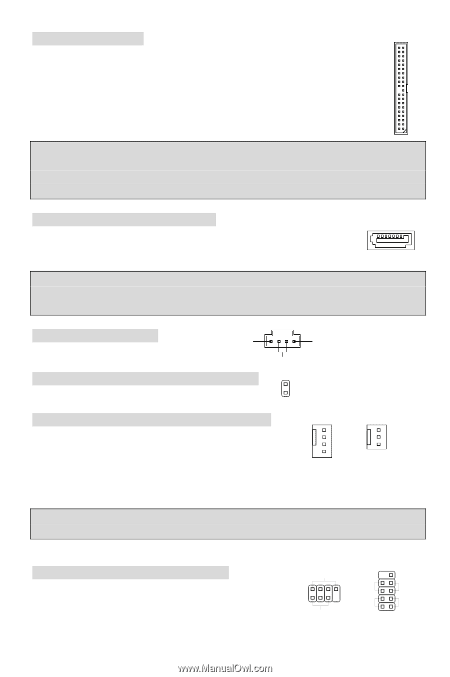
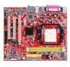
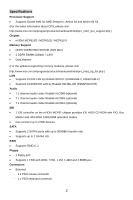
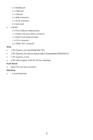
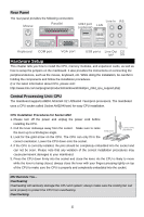
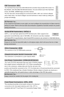
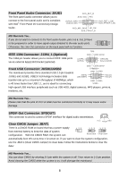
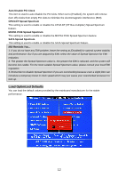
IDE Connector: IDE1 The mainboard has dual Ultra DMA 66/100/133 controller that provides PIO mode 0~4, Bus Master, and Ultra DMA 66/100/133 function. You can connect up to four hard disk drives, CD-ROM, 120MB Floppy and other devices. The first hard drive should always be connected to IDE1. IDE1 can connect a Master and a Slave drive. You must configure second hard drive to Slave mode by setting the jumper accordingly. MSI Reminds You... If you install two hard disks on one cable, you must configure the second drive to Slave mode by setting its jumper. Refer to the hard disk documentation supplied by hard disk vendors for jumper setting instructions. Serial ATAII Connectors: SATA1~2 SATA 1, 2 are dual high-speed Serial ATA interface ports. Each supports 2nd generation serial ATA data rates of 300 MB/s. All connectors are fully compliant with Serial ATA 2.0 specifications. Each Serial ATAII connector can connect to 1 hard disk device. MSI Reminds You... Please do not fold the serial ATA cable in a 90-degree angle, which will cause the loss of data during transmission. CD In Connector: JCD1 R The connector is for CD-ROM audio connector. Chassis Intrusion Switch Connector: JCI1 This connector is connected to a 2-pin chassis switch. L GND 1 CINTRU 2 GND Fan Power Connectors: CPUFAN1/SYSFAN1 The 4-pin CPUFAN1 (processor fan) and 3-pin SYSFAN1 (system fan) support system cooling fan with +12V. When connecting the wire to the connectors, always take note that the red wire is the GND +12V Sensor Control GND +12V Sensor positive and should be connected to the +12V, the black wire is Ground and should be connected to GND. If the mainboard has a System Hardware Monitor chipset on-board, you must use a specially designed fan with speed sensor to take advantage of the CPU fan control. MSI Reminds You... Always consult the vendors for the proper CPU cooling fan. Front Panel Connectors: JFP1, JFP2 The mainboard provides a front panel connector for electrical connection to the front panel switches and LEDs. JFP1 is compliant with Intel® Front Panel I/O Connectivity Design Guide. 7 10 9 Speaker + -- + -+ Power Reset 2 8 Switch Switch 1 7 Power HDD LED LED Power LED 21 JFP2 JFP1
-
 1
1 -
2
-
3
-
4
-
5
-
6
-
7
-
 8
8 -
 9
9 -
 10
10 -
 11
11 -
 12
12 -
 13
13 -
 14
14 -
 15
15 -
 16
16 -
 17
17 -
 18
18 -
19
-
20
-
21
-
22
-
23
-
24
-
25
-
26
-
27
-
28
-
29
-
30
-
31
-
32
-
33
-
34
-
35
-
36
-
37
-
38
-
39
-
40
-
41
-
42
-
43
-
44
-
45
-
46
-
47
-
48
-
49
-
50
-
51
-
52
-
53
-
54
-
55
-
56
-
57
-
58
-
59
-
60
-
61
-
62
-
63
-
64
-
65
-
66
-
67
-
68
-
69
-
70
-
71
-
72
-
73
-
74
-
75
-
76
-
77
-
78
-
79
-
80
-
81
-
82
-
83
-
84
-
85
-
86
-
87
-
88
-
89
-
90
-
91
-
92
-
93
-
94
 |
 |