MSI KM4AM-V User Guide
MSI KM4AM-V - Motherboard - Micro ATX Manual
 |
UPC - 816909006056
View all MSI KM4AM-V manuals
Add to My Manuals
Save this manual to your list of manuals |
MSI KM4AM-V manual content summary:
- MSI KM4AM-V | User Guide - Page 1
if not installed and used in accordance with the instruction manual, may cause harmful interference to radio communications. Operation VOIR LA NOTICE D'NSTALLATION AVANT DE RACCORDER AU RESEAU. Micro-Star International MS-7061 This device complies with Part 15 of the FCC Rules. Operation is subject - MSI KM4AM-V | User Guide - Page 2
of their respective owners. AMD, Athlon™ Athlon™XP, Thoroughbred™ and Duron™ are registered trademarks of trademarks of the Personal Computer Memory Card International Association. Revision Multi-language version for PCB 1.x April 2004 with chipsets VIA® KM400/KM400A/KM266 Pro & VT8237 V1.1 - MSI KM4AM-V | User Guide - Page 3
1. Always read the safety instructions carefully. 2. Keep this User Manual for future reference. 3. Keep this equipment away shock. 11. If any of the following situations arises, get the equipment checked by a service personnel: - The power cord or plug is damaged. - Liquid has penetrated into the - MSI KM4AM-V | User Guide - Page 4
Table of Content English 1 Deutsch 15 Français 31 45 59 Nederlands 71 85 iv - MSI KM4AM-V | User Guide - Page 5
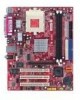
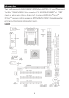
KM4M-V/KM4AM-V/KM3M-V Series (MS-7061 v1.X) micro ATX mainboard. The KM4M-V/KM4AM-V/KM3M-V Series is based on VIA ® KM400/KM400A/KM266 Pro & VT8237 chipsets for optimal system efficiency. Designed to fit the advanced AMD ® AthlonTM/AthlonTM XP/DuronTM processors in 462 pin package, the KM4M-V/KM4AM - MSI KM4AM-V | User Guide - Page 6
® AthlonTM/AthlonTM XP/DuronTM (Socket 462) processor. ! Supports from 1100MHz up to 3000+ or above @ 266/333 MHz. (For the latest information about CPU, please visit http://www.msi.com.tw/program/products/mainboard/mbd/pro_mbd_cpu_support.php ) Chipset ! VIA ® KM266 Pro/KM400/KM400A chipset - FSB - MSI KM4AM-V | User Guide - Page 7
-In/Line-Out/Mic) ports. - COM2 on board with pin header (Intel pin-define). Audio - VIA1617A codec. - 5.1 channel AC'97 software Audio. LAN - VIA VT8237 integrated MAC + VIA 6103 PHY. - 1 RJ45 LAN Jack. BIOS ! The mainboard BIOS provides "Plug & Play" BIOS which detects the peripheral devices and - MSI KM4AM-V | User Guide - Page 8
the instructions on connecting the peripheral devices, such as the mouse, keyboard, etc. While doing the installation, be careful in holding the components and follow the installation procedures. Central Processing Unit: CPU The mainboard supports AMD ® AthlonTM/AthlonTM XP/DuronTM processor in - MSI KM4AM-V | User Guide - Page 9
Memory Speed/CPU FSB Support Matrix Memory the correct installation procedures may cause permanent damages to your mainboard. 5. Press the CPU down firmly into the socket socket. Installing the CPU Fan The following instructions will guide you through the heat sink installation procedures. Please - MSI KM4AM-V | User Guide - Page 10
properly, at least one DIMM module must be installed. (For the updated supporting memory modules, please visit http://www.msi.com.tw/program/products/mainboard/mbd/pro_mbd_trp_list.php ) Install at least one DIMM module on the slots. Memory modules can be installed on the slots in any order. You can - MSI KM4AM-V | User Guide - Page 11
mainboard provides a standard floppy disk drive connector that supports 360K BIOS setting and clear the status. R CD-In Connector: JCD1 GND The connector is for CD-ROM audio connector. L GND Fan Power Connectors: FANCPU1/FANSYS1 +12V The FANCPU1 (processor fan) and FANSYS1 (system fan) support - MSI KM4AM-V | User Guide - Page 12
mainboard has a System Hardware Monitor chipset on-board, you must use a specially designed fan with speed sensor to take advantage of the CPU fan control. MSI Reminds You... 1. Always consult the vendors for proper CPU cooling fan. 2. CPUFAN1 supports and a Slave drive. MSI Reminds You... If you - MSI KM4AM-V | User Guide - Page 13
audio and is compliant with Intel ® Front Panel I/O Connectivity Design Guide. AUD_MIC_BIAS AUD_FPOUT_R AUD_MIC HP_ON AUD_FPOUT_L 9 1 10 2 AUD_SPEAKER_L KEY AUD_SPEAKER_R AUD_GND AUD_VCC MSI JUSB2 Serial Port Connector: COM2 1 2 The main board offers one serial port COM2. It is 16550A - MSI KM4AM-V | User Guide - Page 14
The mainboard provides dual high-speed Serial ATA interface ports. The ports support instructions below to adjust the jumpers. 3 3 1 1 SW1 SW2 Jumper CPU Frequency 133 MHz 166 MHz 200 MHz (for KM400A only) SW1 3 1 3 1 3 1 SW2 3 1 3 1 3 1 Clear CMOS Jumper: JBAT1 There is a CMOS RAM on board - MSI KM4AM-V | User Guide - Page 15
RAM, the system can automatically boot OS every time it is turned on. If you want to clear the system configuration, use the 3 3 JBAT1 (Clear CMOS Jumper) to clear data. Follow the instructions 1 1 1 below to clear the data: Keep Data Clear Data MSI main memory. The mainboard supports BIOS - MSI KM4AM-V | User Guide - Page 16
for basic system configurations, such as time, date etc. Advanced BIOS Features Use this menu to setup the items of Award special enhanced features. Advanced Chipset Features Use this menu to change the values in the chipset registers and optimize your system performance. Integrated Peripherals Use - MSI KM4AM-V | User Guide - Page 17
best system performance, but the system stability may be affected. Load Optimized Defaults Use this menu to load factory default settings into the BIOS for stable system performance operations. Set Supervisor Password Use this menu to set Supervisor Password. Set User Password Use this menu to set - MSI KM4AM-V | User Guide - Page 18
EMI). Spread Spectrum When the motherboard's clock generator pulses, the flatter curves. If you do not have any EMI problem, leave the setting at [Disabled] for optimal system stability processor to lock up. For the complete BIOS introduction and setup, please visit MSI website at http://www.msi.com. - MSI KM4AM-V | User Guide - Page 19
Dank für die Wahl des KM4M-V/KM4AM-V/KM3M-V Serie (MS-7061 v1.X) Micro ATX Mainboard. Die KM4M-V/KM4AM-V/KM3M-V Serie basiert auf dem VIA ® KM400/KM400A/KM266 Pro & Chipsatz für optimale Systemeffizienz. . Es wurde für den fortgeschrittenen AMD ® AthlonTM/AthlonTM XP/DuronTM Prozessors in 462 Geh - MSI KM4AM-V | User Guide - Page 20
XP/DuronTM (Socket 462) Prozessor. ! Unterstützt von 1100 MHz bis 3000+ oder schneller bei 266/333 MHz FSB. (Für die neuesten CPU-Kompatiblitäts-Informationen besuchen Sie bitte die folgende Webseite: http://www.msi.com.tw/program/products/mainboard Sound Board Peripherie ! On-Board Peripherie beinhaltet: - - MSI KM4AM-V | User Guide - Page 21
-Kontaktstecker onboard (Intel Pin-Spezifikation) Audio - VIA1617A Codec. - 5.1 Kanal AC'97 Software Audio. Netzwerk - VIA VT8237 Integrierter MAC + VIA 6103 PHY. - 1 RJ45 Netzwerkanschluss BIOS ! Das Mainboard BIOS integriert das "Plug & Play" BIOS, welches Peripheriegeräte und Erweiterungskarten - MSI KM4AM-V | User Guide - Page 22
Parallel Port LAN USB Ports Keyboard COM port VGA port USB Ports Line In Line Out Mic Das Mainboard unterstützt AMD ® AthlonTM/AthlonTM XP/DuronTM Prozessoren im Sockel 462 Format. Das Mainboard folgende Webseite: http://www.msi.com.tw/program/products/mainboard/mbd/pro_mbd_cpu_support.php ) - MSI KM4AM-V | User Guide - Page 23
CPU komplett in den Sockel versunken und könnne nicht mehr gesehen werden, Bitte beachten Sie, dass beim falschen Eisetzen der CPU in den Sockel das Mainboard und die CPU zerstört werden können! 5. Drücken Sie nochmal auf die CPU und klappen dabei den Hebel wieder herunter, bis er einrastet. Dabei - MSI KM4AM-V | User Guide - Page 24
, passen Sie auf, dass Sie nicht von der Befestigungsfeder abrutschen und dabei das Mainboard beschädigen. 4. Schliessen Sie den Stecker des Prozessorkühlers an den Anschluss FANCPU1 des Mainboards an. MSI erinnert Sie... Überhitzung... Überhitzung beschädigt Ihre CPU und ds gesamte System ernsthaft - MSI KM4AM-V | User Guide - Page 25
eingesetzt werden. (Für die neuesten Speicher-Kompatiblitäts-Informationen besuchen Sie bitte die folgende Webseite: http://www.msi.com.tw/program/products/mainboard/mbd/pro_mbd_trp_list.php ) Speichermodule können in beliebiger Reihenfolge installiert werden. Sie können sowohl einseitige als auch - MSI KM4AM-V | User Guide - Page 26
verwendet werden. Wenn das Gehäuse offen ist, dann ist der Schalter GND 2 CINTRU 1 geschlossen. Das Mainboard zeichnet diesen Status auf.. Um die Warnmeldung zu löschen, müssen Sie in das BIOS und dort den Status zurücksetzen. R CD-In Anschluss: JCD1 GND Hier können Sie das Audiokabel Ihres - MSI KM4AM-V | User Guide - Page 27
die Lüfterdrehzahl anhand der CPU-Temperatur. IDE Anschlüsse: IDE1/IDE2 Das Mainboard hat einen 32-bit erweiterten PCI IDE und Ultra DMA 33/66/100 (Sekundärer IDE Anschluss): IDE2 unterstützt Master und Slave Laufwerke. MSI erinnert Sie... Wenn Sie zwei IDE-Laufwerke an einem IDE-Kabel anschließ - MSI KM4AM-V | User Guide - Page 28
Der JAUD1 Gehäusefront-Anschluss erlaubt es Ihnen, Audio-Anschlüsse an der Vorderseite Ihres Gehäuses mit dem Mainboard zu verbinden. Der Anschluss entspricht dem "Intel ® Front Panel I/O Connectivity Design Guide" AUD_MIC_BIAS AUD_FPOUT_R AUD_MIC HP_ON AUD_FPOUT_L 9 1 10 2 AUD_SPEAKER_L KEY - MSI KM4AM-V | User Guide - Page 29
Data Set Ready Request To Send Clear To Send Ring Indicate Serial ATA HDD Anschlüsse: SATA1/SATA2 (bei KM400/KM400A ) Das Mainboard ist mit zwei Hochgeschwindigkeits Serial ATA Schnittstellen SATA2 ausgestattet. Die Anschlüsse unterstützen die erste Generation von Serial ATA mit 7 1 einer - MSI KM4AM-V | User Guide - Page 30
(Nur bei KM400A) SW1 3 1 3 1 3 1 SW2 3 1 3 1 3 1 CMOS Rücksetz-Jumper: JBAT1 Im Mainboard ist ein CMOS Speicher integriert, welches von 1 einer Batterie versorgt wird, um die Systemkonfiguration zu speichern. Das CMOS RAM ermöglicht es, das System 3 1 Keep Data 3 1 Clear Data automatisch zu - MSI KM4AM-V | User Guide - Page 31
von schnellen 3D-Grafuikkarten entwickelt wurde. AGP ermöglicht 66MHz, 64-Bit Datenübertragung für den Grafik-Kontroller direkt zum Hauptspeicher. Das Mainboard unterstützt AGP-Grafikkarten mit 4X (nur bei KM266Pro)/8X (nur bei KM400 & KM400A) Übertragung. PCI (Peripheral Component Interconnect - MSI KM4AM-V | User Guide - Page 32
CMOS Features Hier können Sie die Grundeinstellungen wie Laufwerke, Dastum, Uhrzeit einstellen. Advanced BIOS Features Hier stellen Sie erweiterte Einstellungen des Award-BIOS ein. Advanced Chipset Features Hier stellen Sie Chipsatzregister ein und können die Systemperformance optimieren. Integrated - MSI KM4AM-V | User Guide - Page 33
Sie ein Supervisor-Passwort einstellen. Set User Password Hier können Sie ein Benutzerpasswort einstellen. Save & Exit Setup Hier speichern Sie die Einstellungen und verlassen das BIOS-Setup. Exit Without Saving Hier können Sie alle aktuellen Änderungen rückgängig machen und das - MSI KM4AM-V | User Guide - Page 34
Frequenzspektrum verteilt und erhöht somit die Elektromagnetische Verträglichkeit (EMV). Wenn SIe damit keine Probleme haben, lassen Sie diese Funktion aus, um die Systemkompatibilität zu erhöhen. For the complete BIOS introduction and setup, please visit MSI website at http://www.msi.com.tw. 30 - MSI KM4AM-V | User Guide - Page 35
KM4AM-V/KM3M-V Series (MS-7061 v1.X). La KM4M-V/KM4AM-V/KM3M-V Series est basée sur les chipsets VIA ® KM400/KM400A/KM266 Pro & VT8237 permettant d'obtenir un système performant. Cette carte gère les processeurs de dernière génération AMD ® AthlonTM/AthlonTM XP/DuronTM (socket 462). La KM4M-V/KM4AM - MSI KM4AM-V | User Guide - Page 36
/AthlonTM XP/DuronTM (Socket 462). ! Supporte de 1100MHz jusqu'à 3000+ ou supérieur @266/333 MHz. (Veuillez vous référer aux dernières informations mises en ligne sur notre site à cette adresse : http://www.msi.com.tw/program/products/mainboard/mbd/pro_mbd_cpu_support.php ) Chipset ! Chipset VIA - MSI KM4AM-V | User Guide - Page 37
2 FDD (360K, 720K, 1.2M, 1.44M et 2.88Mbytes). - 1 port série et 1 port VGA. - 1 port parallèle supportant les modes SPP/EPP/ECP. - 2 SATA connecteurs (pour KM400 & KM400A uniquement). - 8 ports USB 2.0 (Arrière * 4/ Façade * 4). - 3 ports audio (Line-In/Line-Out/Mic). - COM2 intégré (définition des - MSI KM4AM-V | User Guide - Page 38
Ports Keyboard COM port VGA port USB Ports Line la carte. Vous aurez aussi des instructions relatives à la connexion des périphériques La carte mère supporte les processeurs AMD ® AthlonTM/AthlonTM XP/DuronTM socket 462 http://www.msi.com.tw/program/products/mainboard/mbd/pro_mbd_cpu_support.php - MSI KM4AM-V | User Guide - Page 39
Matrice de Support Mémoire/CPU FSB Mémoire FSB 266 MHz 333 MHz 400 MHz le CPU ne peut plus bouger et reste fixe sur le socket. Installation du Ventilateur de CPU Les instructions ci-dessous vous permettent de connaître la procédure d'installation du ventilateur. Veuillez consulter votre revendeur - MSI KM4AM-V | User Guide - Page 40
Pour fonctionner correctement il faut installer au moins un module DIMM. (Pour connaître les modules de mémoire supportés, veuillez visiter http://www.msi.com.tw/program/products/mainboard/mbd/pro_mbd_trp_list.php ) Les modules de mémoire ne peuvent être installés que dans un seul sens. Vous pouvez - MSI KM4AM-V | User Guide - Page 41
enlever en passant par le BIOS. R Conneteur CD-In : JCD1 GND Le connecteur est destiné au branchement audio du CD-ROM. L Conneteurs d'Alimention Ventilateurs : FANCPU1/FANSYS1 GND Le FANCPU1 (Processeur de ventilateur) et le FANSYS1 (ventilateur de système) +12V supportent +12V. Lors de la - MSI KM4AM-V | User Guide - Page 42
du CPU. MSI Vous Rappelle... 1. Il faut toujours consulter votre revendeur au sujet du ventilateur. 2. Le CPUFAN1 supporte le contrôle re. L'IDE2 peut aussi recevoir un matériel en Maître et en Esclave. MSI Vous Rappelle... Si vous voulez installer deux disques durs, vous devez configurer le second - MSI KM4AM-V | User Guide - Page 43
Front Panel I/O Connectivity. AUD_MIC_BIAS AUD_FPOUT_R AUD_MIC HP_ON AUD_FPOUT_L 9 1 10 2 AUD_SPEAKER_L KEY AUD_SPEAKER_R AUD_GND AUD_VCC MSI Vous Rappelle... Si vous ne voulez pas connecter l'audio en façade à l'aide des broches 5 & 6, 9 & 10 doivent être recouvertes par un cavalier pour - MSI KM4AM-V | User Guide - Page 44
To Send Ring Indicate Connecteurs Série ATA HDD : SATA1/SATA2 (pour KM400/KM400A) La carte procure deux ports très rapides Serial ATA. Les ports supportent la 1ère SATA2 génération de Serail ATA avec un taux de transfert de 150 MB/s et sont compatible 7 1 avec les spécifications du Serial - MSI KM4AM-V | User Guide - Page 45
mémoire CMOS RAM de retenir 1 les modifications que vous faites dans le BIOS. Si vous voulez 3 1 Keep Data 3 1 Clear Data effacer les informations stockées dans cette mémoire vous devez utiliser le JBAT1 (Clear CMOS Jumper). Suivez les instructions ci-dessous pour effacer les données : MSI Vous - MSI KM4AM-V | User Guide - Page 46
est particulièrement bien adaptée aux applications 3D. Contrôleur 66MHz, 32-bit avec accès direct à la mémoire principale. Le slot supporte les cartes AGP 4X (pour KM266Pro uniquement)/8X (pour KM400 & KM400A uniquement). Slots PCI (Peripheral Component Interconnect) Les slots PCI vous permettent - MSI KM4AM-V | User Guide - Page 47
ments standard du BIOS. Advanced BIOS Features Cette fonction permet de paramétrer des éléments avancés du Bios. Advanced Chipset Features Cette le power management. PNP/PCI Configurations Apparaît si votre système supporte PNP/PCI. PC Health Status Cette option vous permet de visualiser l'é - MSI KM4AM-V | User Guide - Page 48
voltage. Load Fail-Safe Defaults Utiliser ce menu pour charger les valeurs du BIOS permettant d'obtenir les meilleures performances, mais la stabilité du système n'est d'éviter tout problème. Pour des informations plus complètes sur le BIOS, veuillez visiter notre site web : http://www.msi.com.tw. 44 - MSI KM4AM-V | User Guide - Page 49
简介 KM4M-V/KM4AM-V/KM3M-V 系列(MS-7061 v1.X)micro ATX 主板。 KM4M-V/KM4AM-V/KM3M-V VIA® KM400/KM400A/KM266 Pro 和 VT8237 KM4M-V/KM4AM-V/KM3M-V 462 AMD® AthlonTM/AthlonTM XP/DuronTM 规格 Top : mouse Bottom: keyboard SOCKET 462 FANCPU1 CONN 1 FDD 1 Top : Parallel Port Bottom: COM A VGA port - MSI KM4AM-V | User Guide - Page 50
/AthlonTM XP/DuronTM(Socket 462 1100MHz 达 3000 266/333 MHz CPU http://www.msi.com.tw/program/products/mainboard/mbd/pro_mbd_cpu_support Sound AC97 Ultra DMA 33/66/100/133 master 模式 EIDE ACPI 和 PC2001 USB2.0 8237 支持 8 2 184-pin DDR DIMMS 2GB http://www.msi.com.tw/program/products/mainboard - MSI KM4AM-V | User Guide - Page 51
- 1 SPP/EPP/ECP 模式 - 2 个 SATA KM400 & KM400A) - 8 个 USB 2.0 4/ 前置* 4) - 3 Line-In/Line-Out/Mic Intel COM2 音频 - VIA1617A 5.1 声道 AC'97 LAN - VIA VT8237 集成于 MAC + VIA 6103 PHY - 1 个 RJ45 LAN 插孔 BIOS BIOS 提供"Plug & Play DMI Micro-ATX 245 mm x 192mm 6 PS2 VRAM 64MB CPU 47 - MSI KM4AM-V | User Guide - Page 52
Port LAN USB Ports Keyboard COM port VGA port USB Ports Line In Line Out Mic In 硬件安装 CPU CPU 462 AMD® AthlonTM/AthlonTM XP/DuronTM Socket A 的 CPU CPU CPU CPU CPU CPU http://www.msi.com.tw/program/products/mainboard/mbd/pro_mbd_cpu_support.php ) CPU 如果 CPU = 100MHz - MSI KM4AM-V | User Guide - Page 53
CPU FSB 内存 FSB 266 MHz 333 MHz 400 MHz KM400A) DDR 266 OK OK OK DDR 333 OK OK OK DDR 400 KM400A) OK OK OK 462 CPU 安装 1 2 90 度角。. 3. 寻找 CPU CPU 4. 如果 CPU 5 CPU CPU 指按住 CPU CPU 安装 CPU 风扇 CPU 1. 将您的 CPU CPU 上。 2 CPU 3 4 CPU CPU CPU 更换 CPU ATX CPU 49 - MSI KM4AM-V | User Guide - Page 54
内存 2 个 184-pin、2.5V 的 DDR DIMM DDR266/DDR333/DDR400 KM400A)DDR SDRAM 2GB http://www.msi.com.tw/program/products/mainboard/mbd/pro_mbd_trp_list.php DDR 1. DDR DIMM 2. 将 DDR DDR 3. DIMM Volt Notch 50 - MSI KM4AM-V | User Guide - Page 55
12V 20 10 ATX 12V JPW1 12 GND GND 此 12V CPU 供电。 12V 12V 34 FDD1 FDD,支持 360K、720K、1.2M、1.44M 和 2.88M JCI1(选配) GND 2 CINTRU 1 2-pin BIOS 设定程 R CD-In 接口:JCD1 CD-ROM GND L 51 - MSI KM4AM-V | User Guide - Page 56
FANCPU1/FANSYS1 GND FANCPU1 FANSYS1 12V 12V 用 3 -pin 12V,而 SENSOR GND 1 CPU 2. CPUFAN1 PC Alert 的速度。 IDE 接口:IDE1/IDE2 32-bit 增强 PCI IDE 和 Ultra DMA 33/66/100/133 IDE PIO mode 0-4,Bus Master 和 Ultra DMA 33/66/100/133 4 个 IDE CD-ROM、 120MB IDE IDE1 IDE1 IDE2 - MSI KM4AM-V | User Guide - Page 57
JFP1/JFP2 2 JFP1 和 JFP2。JFP1 是符合 Intel® I/O Power Power LED Switch 2 10 1 9 Speaker 2 8 1 7 HDD Reset LED Switch JFP1 Power LED JFP2 JAUD1 JAUD1 JAUD1 是符合 Intel® I/O AUD_MIC_BIAS AUD_FPOUT_R AUD_MIC HP_ON AUD_FPOUT_L 9 1 10 2 AUD_SPEAKER_L KEY AUD_SPEAKER_R AUD_GND - MSI KM4AM-V | User Guide - Page 58
COM2 1 2 COM2。是 16550A 16 bytes FIFO,可用来 9 10 针脚 1 2 3 4 5 信号 DCD SIN SOUT DTR GND 说明 Data Carry Detect Serial In or Receive Data Serial Out or Transmit Data 针脚 6 7 8 9 信号 DSR RTS CTS RI 说明 Data Set Ready Request To Send Clear To Send Ring Indicate Serial ATA HDD 接口:SATA1/SATA2 - MSI KM4AM-V | User Guide - Page 59
清除 CMOS 跳线:JBAT1 CMOS RAM CMOS RAM 是 CMOS RAM 用 JBAT1(清除 CMOS 1 数据: 3 1 Keep Data 3 1 Clear Data 2-3 CMOS 1-2 CMOS AGP AGP AGP AGP 3D 66MHz,32-bit 4X (仅对于 KM266Pro)/ 8X (仅对于 KM400 & KM400A) AGP 显 卡。. PCI PCI BIOS 设置。 PCI IRQ PCI 的 IRQ PCI 总线的 INT A# ~ INTD - MSI KM4AM-V | User Guide - Page 60
F11: Boot Menu F12: Network boot TAB: Logo Setup Reset 键, Ctrl> 和 - MSI KM4AM-V | User Guide - Page 61
Set Supervisor Password Set User Password Save & Exit Setup CMOS Setup 程序。 Exit Without Saving CMOS Setup 程序。 57 - MSI KM4AM-V | User Guide - Page 62
Auto Detect PCI/DIMM Clk PCI/DIMM PCI Enabled PCI EMI Spread Spectrum EMI Disabled Enabled BIOS http://www.msi.com.tw. 58 - MSI KM4AM-V | User Guide - Page 63
簡介 KM4M-V/KM4AM-V/KM3M-V 系列 (MS-7061 v1.X) micro ATX KM4M-V/KM4AM-V/KM3M-V VIA® KM400/KM400A/KM266 Pro & VT8237 462 腳位的 AMD® AthlonTM / AthlonTM XP / DuronTM KM4M-V/KM4AM-V/KM3M-V Top : mouse Bottom: keyboard SOCKET 462 FANCPU1 CONN 1 FDD 1 Top : Parallel Port Bottom: COM A VGA port - MSI KM4AM-V | User Guide - Page 64
462 架構的 AMD ® AthlonTM/AthlonTM XP/DuronTM 1100MHz 達到 3000 FSB@ 266/333 MHz.。 CPU http://cweb.msi.com.tw VIA® KM266 Pro/KM400 33/66/100/133 PCI EIDE ACPI 及 PC2001 USB 2.0 184-pin DDR DIMM 2GB http://cweb.msi.com.tw AGP 1.5V 4X KM266Pro)/ AGP 8 X KM400 & KM400A 32 位元 PCI 2.2 3.3v - MSI KM4AM-V | User Guide - Page 65
360K/720K/1.2M/1.44M/2. 88MB VGA SPP/EPP/ECP SATA KM400 & KM400A USB2.0 4/面板*4 COM2 腳針(Intel VIA1617A 5.1 聲道 AC'97 LAN VIA VT8237 MAC+VIA 6103 PHY RJ-45 BIOS BIOS DMI 24.5 x 19.2 公分(寬)Micro-ATX PS2 VRAM 可高達 64MB 61 - MSI KM4AM-V | User Guide - Page 66
背板 硬體安裝 Socket462 規格的 CPU AMD ® AthlonTM/AthlonTM XP/DuronTM CPU CPU CPU http://www.msi.com.tw/program/products/mainboard/mbd/pro_mbd_cpu_support.php ) CPU 如果 CPU 時脈 = 則 CPU = = = 100MHz 14 主時脈 x 100MHz x 114 1.4GHz 62 - MSI KM4AM-V | User Guide - Page 67
CPU FSB Memory FSB 266 MHz 333 MHz 400 MHz (僅限 KM400A) DDR 266 OK OK OK DDR 333 OK OK OK DDR 400 (僅限 KM400A) OK OK OK 安裝 Socket 462 1 2 90 度角。 3. 找出 CPU CPU 4 5 安裝 CPU 風扇 CPU 1. 請您將 CPU CPU 2 3 4 MSI CPU CPU 更換 CPU CPU CPU ATX 63 - MSI KM4AM-V | User Guide - Page 68
記憶體 DDR SDRAM DIMM 插槽(184-pin DDR266/DDR333/DDR400(僅限 KM400A DDR DIMM 2GB http://cweb.msi.com.tw DIMM DIMM 1GB DDR 模組 1. DDR DIMM 2. 將 DIMM DIMM 3 Volt Notch ATX 300 11 1 3.3V 3.3V -12V 3.3V ATX 20-pin CONN1 GND PS_ON - MSI KM4AM-V | User Guide - Page 69
FDD 1 360KB、720KB、 1.2MB、1.44MB 及 2.88MB。 JCI1(選購) 2-pin GND CINTRU 2 1 BIOS CD JCD1 R GND L FANCPU1/FANSYS1 GND FANCPU1 FANSYS1 12V 的電壓 +12V 3-pin SENSOR 12V GND CPU 冷卻 MSI 1 CPU 風扇。 2. FANCPU1 PC Alert CPU CPU IDE IDE1/ IDE2 32 - MSI KM4AM-V | User Guide - Page 70
8 1 7 Power LED JFP2 JAUD1 JAUD1 Intel AUD_MIC_BIAS AUD_FPOUT_R AUD_MIC HP_ON AUD_FPOUT_L 9 1 10 2 AUD_SPEAKER_L KEY AUD_SPEAKER_R AUD_GND AUD_VCC MSI 5、6、9 及 10 9 1 10 2 面板 USB JUSB1 / JUSB2 USB2.0 連接器 JUSB1/JUSB2 Intel USB2.0 USB1- VCC USB1+ GND USBOC 2 10 - MSI KM4AM-V | User Guide - Page 71
COM2 9-pin 的 DIN COMA 1 2 COM2 16 位元組 FIFOs 的 16550A 9 10 腳位 1 2 3 4 5 訊號 DCD SIN SOUT DTR GND 說明 Data Carry Detect Serial In or Receive Data Serial Out or Transmit Data 腳位 6 7 8 9 訊號 DSR RTS CTS RI 說明 Data Set Ready Request To Send Clear To Send Ring Indicate SATA1/ - MSI KM4AM-V | User Guide - Page 72
清除 CMOS JBAT1 CMOS RAM 3 3 保存 BIOS CMOS RAM 1 1 1 BIOS BIOS Keep Data Clear Data JBAT1 Keep Data Clear Data MSI 2-3 CMOS AGP 插槽 AGP AGP 3D 66MHz、32 AGP4X KM266Pro)/ 8 X KM400 & KM400A PCI 插槽 BIOS PCI IRQ Interrupt request PCI 的 IRQ PCI - MSI KM4AM-V | User Guide - Page 73
:Setup F11:Boot Menu F12:Network boot TAB:Logo RESET 按 Ctrl>、及 - MSI KM4AM-V | User Guide - Page 74
BIOS Load Optimized Defaults BIOS Set Supervisor Password Set User Password Save & Exit Setup CMOS Exit Without Saving CMOS Auto Detect DIMM/PCI ClK PCI PCI EMI PCI Enabled)、關閉(Disabled)。 Spread Spectrum EMI Disabled EMI Enable BIOS http://cweb.msi.com.tw 70 - MSI KM4AM-V | User Guide - Page 75
uw aankoop van het KM4M-V/KM4AM-V/KM3M-V Series (MS-7061 v1.X) micro ATX moederbord. De KM4M-V/KM4AM-V/KM3M-V Series is gebaseerd op de VIA ® KM400/KM400A/KM266 Pro & VT8237 chipset. De KM4M-V/KM4AM-V/KM3M-V Serie is ontworpen voor de AMD ® AthlonTM/AthlonTM XP/DuronTM processor met 462 pinnen en - MSI KM4AM-V | User Guide - Page 76
AMD ® AthlonTM/AthlonTM XP/DuronTM (Socket 462) processor. ! Ondersteunt vanaf 1100 MHz tot 3000+ of hoger op 266/333MHz. (Voor de meest recente informatie over processor-ondersteuning, kijk op http://www.msi.com.tw/program/products/mainboard/mbd/pro_mbd_cpu_support.php ) Chipset ! VIA ® KM266 Pro - MSI KM4AM-V | User Guide - Page 77
/Mic-in Aansluiting - COM2 pin connector (Intel pinconfiguratie). Audio - VIA1617A codec. - 5.1 kanaals AC'97 Software Audio LAN - VIA VT8237 geïntegreerd MAC + VIA 6103 PHY. - 1 RJ45 LAN Jack. BIOS ! Het moederbord heft een "Plug & Play" BIOS die automatisch de extra apparaten in het system herkent - MSI KM4AM-V | User Guide - Page 78
Port LAN USB Ports Keyboard COM port VGA port USB Ports Line In Line de 462 pins AMD ® AthlonTM/AthlonTM XP/DuronTM processor. Het moederbord gebruikt een CPU socket voor de CPU, kijk dan op http://www.msi.com.tw/program/products/mainboard/mbd/pro_mbd_cpu_support.php Een voorbeeld voor het - MSI KM4AM-V | User Guide - Page 79
uw vingers op de bovenkant van de CPU te drukken, zodat de CPU volledig in de socket valt. Installatie van de CPU koeler Omdat de processor technologie voortschrijdt naar grotere snelheden en hogere prestaties, is koeling in toenemende mate belangrijk. Om de warmte af te voeren, dient U het CPU - MSI KM4AM-V | User Guide - Page 80
plaatsen in de DIMM sloten. Om te kunnen werken moet er minstens 1 geheugenmodule zijn geplaatst. (Voor meer informatie:http://www.msi.com.tw/program/products/mainboard/mbd/pro_mbd_trp_list.php ) Het installeren van DDR modules 1. De geheugenmodule heeft een uitsparing in het midden. De module past - MSI KM4AM-V | User Guide - Page 81
waarmee GND 2 CINTRU 1 onrechtmatig openen van de kast gedetecteerd kan worden. Het systeem zal een melding van deze schakelaar vastleggen in de BIOS, zodat u naderhand altijd kunt achterhalen of de kast open is geweest.Op het moederbord zit een standaar floppy aanlsuiting voor 360K R CD - MSI KM4AM-V | User Guide - Page 82
opstarten) moet altijd op IDE1 aangesloten worden. U kunt de apparaten in Master/Slave configuratie aansluiten. IDE2 (Secondary IDE Connector): Zie IDE1. MSI Herinnert U Eraan... Als U twee apparaten op 1 IDE kabel aansluit, dan moet U de Master/Slave instellingen wel juist maken! Doet U dit niet - MSI KM4AM-V | User Guide - Page 83
kunt U verbinden met het audio aansluitingen op de voorzijde van uw computerkast en voldoet aan de Intel ® Front Panel I/O Connectivity Design Guide. AUD_MIC_BIAS AUD_FPOUT_R AUD_MIC HP_ON AUD_FPOUT_L 9 1 10 2 AUD_SPEAKER_L KEY AUD_SPEAKER_R AUD_GND AUD_VCC MSI Herinnert U eraan... Pin - MSI KM4AM-V | User Guide - Page 84
Seriële Poort Connector: COM2 1 2 Het moederbord biedt één seriële poort COM2. Het is een 16550A communicatie poort dat 16 bytes FIFO's verzend/ontvangt. U kunt hier een seriële muis of andere seriële 9 10 randappartuur op aansluiten. PIN SIGNAAL 1 DCD 2 SIN 3 SOUT 4 DTR 5 GND - MSI KM4AM-V | User Guide - Page 85
. Met de Clear CMOS jumper kunt U alle instellingen van 3 1 Keep Data 3 1 Clear Data het BIOS wissen. Let op de plaatjes hiernaast om te zien hoe u de jumper kunt gebruiken om de instellingen te wissen. MSI Herinnert U Eraan... U kunt de CMOS leeg maken door pin 2 en 3 te verbinden. Zorg er na - MSI KM4AM-V | User Guide - Page 86
documentatie van de uitbreidingskaart om te zien of U nog speciale hardware of software instellingen moet uitvoeren, zoals jumpers, switches of de BIOS configuratie. PCI Interrupt Request Routing Middels de IRQ (Interupt Request Line) instellingen kunt U bepalen welke kaart op welk moment signalen - MSI KM4AM-V | User Guide - Page 87
dit menu voor de basis systeem configuraties zoals tijd, datum etc. Advanced BIOS Features Gebruik dit menu om de items van de AMI® features in te stellen. Advanced Chipset Features Gebruik dit menu om veranderingen in de waarden van de chipset aan te brengen en om de prestatie van het systeem te - MSI KM4AM-V | User Guide - Page 88
Load Optimized Defaults Gebruik dit menu om de standaard instellingen van het systeem in de BIOS te laden voor een stabiel systeem en goede prestaties. Set Supervisor Password Gebruik dit resultaat geeft. Voor meer informatie over de BIOS en setup, bezoek dan de MSI website http://www.msi.com.tw. 84 - MSI KM4AM-V | User Guide - Page 89
はじめに KM4M-V/KM4AM-V/KM3M-V MS-7061 v1.X) Micro ATX KM4M-V/KM4AM-V/KM3M-V VIA ® KM400/KM400A/KM266 Pro & VT8237 462 ピンの AMD ® AthlonTM/AthlonTM XP/DuronTM KM4M-V/KM4AM-V/KM3M-V Top : mouse Bottom: keyboard SOCKET 462 FANCPU1 CONN 1 FDD 1 Top : Parallel Port Bottom: COM A VGA port - MSI KM4AM-V | User Guide - Page 90
/ AthlonTM XP / DuronTM 1100MHzから 3000 FSB 266/333 CPU http://www.msi.com.tw/program/products/mainboard/mbd/pro_mbd_cpu_support.php Sound AC'97 Ultra DMA33/66/100/133 対応 EIDE ACPI & PC2001 USB2.0 8237 は 8 4 184-ピン DDR DIMM x 2 ! 最大 2GB http://www.msi.com.tw/program/products/mainboard - MSI KM4AM-V | User Guide - Page 91
- 1 SPP/EPP/ECP 2 SATA KM400 & KM400A のみ) - 8 USB 2.0/1.1 4 4) - 3 Line-In/Line-Out/Mic-In COM2 Intel VIA1617A AC'97 5.1 LAN - VIA VT8237 MAC + VIA 6103 PHY - 1 RJ45 LAN Jack BIOS BIOS Plug & Play Desktop Management Interface(DMI Micro-ATX 245 mm x 192mm 取付 ! 6 PS2 64MB VRAM CPU - MSI KM4AM-V | User Guide - Page 92
LAN USB Ports Keyboard COM port VGA port USB Ports Line In Line Out Mic In Central Processing Unit: CPU 462 ピンの AMD ® AthlonTM/AthlonTM XP/DuronTM Socket A (Socket 462 CPU CPU CPU http://www.msi.com.tw/program/products/mainboard/mbd/pro_mbd_cpu_support.php ) CPU 例えば CPU - MSI KM4AM-V | User Guide - Page 93
CPU FSB 対応表 メモリ FSB 266 MHz 333 MHz 400 MHz (KM400A のみ) DDR 266 OK OK OK DDR 333 OK OK OK DDR 400 (KM400A のみ) OK OK OK Socket 462 CPU 1. CPU 2 90 3 1 CPU 4. CPU CPU 5. CPU CPU CPU Fan CPU 1. CPU CPU 2 3 4. CPU 89 - MSI KM4AM-V | User Guide - Page 94
CPU CPU CPU CPU CPU ATX ATX CPU メモリ 184 ピンの DDR DIMM(Double In-Line Memory Module 2 DDR266/DDR333/DDR400 (KM400A のみ) DDR SDRAM を最大 2GB http://www.msi.com.tw/program/products/mainboard/mbd/pro_mbd_trp_list.php 1 つの DIMM DIMM DDR 1. DDR DIMM VOLT DIMM 1 2. DIMM DIMM 3. DIMM - MSI KM4AM-V | User Guide - Page 95
1 20 10 12 34 FDD1 360K、720K、1.2M、1.44M 及び 2.88M 3.3V 3.3V GND 5V GND 5V GND PW_OK 5V_SB 12V GND 12V JCI1 2 GND CINTRU 2 1 るには、BIOS CD-In JCD1 CD-ROM R GND L 91 - MSI KM4AM-V | User Guide - Page 96
FANCPU1/FANSYS1 12V 3 GND 12V +12V GND SENSOR MSI Reminds You... 1 2. CPUFAN1 PC Alert Windows IDE1/IDE2 PIO 0~4 Ultra DMA 33/66/100/133 32 ビット Enhanced PCI IDE および Ultra DMA 33/66/100/133 4 - MSI KM4AM-V | User Guide - Page 97
2 8 1 7 Power LED JFP2 JAUD1 Intel® Front Panel I/O Connectivity Design Guide AUD_MIC_BIAS AUD_FPOUT_R AUD_MIC HP_ON AUD_FPOUT_L 9 1 10 2 AUD_SPEAKER_L KEY AUD_SPEAKER_R AUD_GND AUD_VCC MSI Reminds You... 9 1 5、6、9、10 10 2 USB JUSB1/JUSB2 2 つの USB2.0 JUSB1 - MSI KM4AM-V | User Guide - Page 98
COM2 COM2 9 ピンの DIN 1 2 16 FIFO 16550A 9 10 PIN SIGNAL 1 DCD 2 SIN 3 SOUT 4 DTR 5 GND DESCRIPTION PIN Data Carry Detect 6 Serial In or 7 Receive Data 8 Serial Out or 9 Transmit Data SIGNAL DSR RTS CTS RI DESCRIPTION Data Set Ready Request To Send Clear To - MSI KM4AM-V | User Guide - Page 99
Bus 100MHz, 133MHz, 166MHz 3 1 SW1 3 1 SW2 CPU 周波数 133 MHz 166 MHz 200 MHz (KM400A のみ) SW1 3 1 3 1 3 1 SW2 3 1 3 1 3 1 クリア CMOS JBAT1 CMOS RAM 1 JBAT1 の 1-2 CMOS CMOS 3 1 Keep Data JBAT1 (Clear CMOS Jumper 3 1 Clear Data MSI Reminds You... CMOS 2-3 1-2 CMOS 95 - MSI KM4AM-V | User Guide - Page 100
AGP (Accelerated Graphics Port AGP AGP AGP とは 3D AGP 4X (KM266Pro の み) / 8X (KM400 & KM400A VGA PCI (Peripheral Component Interconnect PCI BIOS PCI IRQ(interrupt request line I-R-Q PCI の IRQ PCI バス INT A#から INT D PCI Slot 1 PCI Slot 2 PCI Slot 3 Order1 INT A# INT B# INT C# - MSI KM4AM-V | User Guide - Page 101
F11: Boot Menu F12: Network boot TAB: Logo - MSI KM4AM-V | User Guide - Page 102
Load Fail-Safe Defaults BIOS Load Optimized Defaults BIOS Set Supervisor Password Set User Password Save & Exit Setup CMOS Exit Without Saving CMOS Frequency/Voltage Control Auto Detect PCI/DIMM Clk PCI DIMM Spread
-
 1
1 -
 2
2 -
 3
3 -
 4
4 -
 5
5 -
 6
6 -
 7
7 -
8
-
9
-
10
-
11
-
12
-
13
-
14
-
15
-
16
-
17
-
18
-
19
-
20
-
21
-
22
-
23
-
24
-
25
-
26
-
27
-
28
-
29
-
30
-
31
-
32
-
33
-
34
-
35
-
36
-
37
-
38
-
39
-
40
-
41
-
42
-
43
-
44
-
45
-
46
-
47
-
48
-
49
-
50
-
51
-
52
-
53
-
54
-
55
-
56
-
57
-
58
-
59
-
60
-
61
-
62
-
63
-
64
-
65
-
66
-
67
-
68
-
69
-
70
-
71
-
72
-
73
-
74
-
75
-
76
-
77
-
78
-
79
-
80
-
81
-
82
-
83
-
84
-
85
-
86
-
87
-
88
-
89
-
90
-
91
-
92
-
93
-
94
-
95
-
96
-
97
-
98
-
99
-
100
-
101
-
102
 |
 |
i
FCC-B Radio Frequency Interference Statement
This equipment has been tested and found to comply with the limits for a class B digital device, pursuant to part 15 of
the FCC rules. These limits are designed to provide reasonable protection against harmful interference when the
equipment is operated in a commercial environment. This equipment generates, uses and can radiate radio frequency
energy and, if not installed and used in accordance with the instruction manual, may cause harmful interference to
radio communications. Operation of this equipment in a residential area is likely to cause harmful interference, in
which case the user will be required to correct the interference at his own expense.
Notice 1
The changes or modifications not expressly approved by the party responsible for compliance could void the user°s
authority to operate the equipment.
Notice 2
Shielded interface cables and A.C. power cord, if any, must be used in order to comply with the emission limits.
VOIR LA NOTICE D°NSTALLATION AVANT DE RACCORDER AU RESEAU.
Micro-Star International
MS-7061
This device complies with Part 15 of the FCC Rules. Operation is subject to the following two conditions:
(1) this device may not cause harmful interference, and
(2) this device must accept any interference received, including interference that may cause undesired operation
G52-M7061X3