MSI MEG X570S UNIFY-X MAX User Manual
MSI MEG X570S UNIFY-X MAX Manual
 |
View all MSI MEG X570S UNIFY-X MAX manuals
Add to My Manuals
Save this manual to your list of manuals |
MSI MEG X570S UNIFY-X MAX manual content summary:
- MSI MEG X570S UNIFY-X MAX | User Manual - Page 1
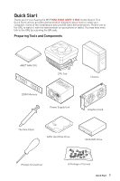
Quick Start Thank you for purchasing the MSI® MEG X570S UNIFY-X MAX motherboard. This Quick Start section provides demonstration diagrams about how to install your computer. Some of the installations also provide video demonstrations. Please link to - MSI MEG X570S UNIFY-X MAX | User Manual - Page 2
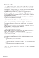
Please adhere to the following instructions to ensure successful computer following situations arises, get the motherboard checked by service personnel: ▪▪Liquid has penetrated into the computer. you can not get it work according to user guide. ▪▪The motherboard has been dropped and damaged. - MSI MEG X570S UNIFY-X MAX | User Manual - Page 3
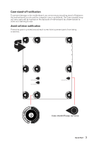
Case stand-off notification To prevent damage to the motherboard, any unnecessary mounting stand-off between the motherboard circuits and the computer case is prohibited. The Case standoff keep out zone signs will be marked on the backside of motherboard (as shown below) to serve as a warning to - MSI MEG X570S UNIFY-X MAX | User Manual - Page 4
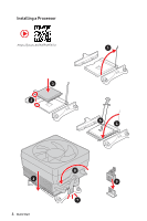
Installing a Processor https://youtu.be/Xv89nhFk1vc 3 2 1 5 4 6 4 Quick Start 8 9 7 - MSI MEG X570S UNIFY-X MAX | User Manual - Page 5
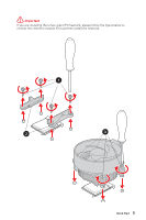
⚠⚠Important If you are installing the screw-type CPU heatsink, please follow the figure below to remove the retention module first and then install the heatsink. 1 2 3 Quick Start 5 - MSI MEG X570S UNIFY-X MAX | User Manual - Page 6
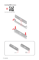
Installing DDR4 memory ⚽ ⚽ http://youtu.be/T03aDrJPyQs 6 Quick Start DIMMB1 DIMMA1 DIMMB1 - MSI MEG X570S UNIFY-X MAX | User Manual - Page 7
Connecting the Front Panel Header ⚽ ⚽ http://youtu.be/DPELIdVNZUI POPWOEWRELREHLDD-EDDL+ED RESET SW POWER SW Power LED Power Switch - -+ -- ++ JFP1 2 1 + 10 9 Reserved HDD LED Reset Switch 1 HDD LED + 2 3 HDD LED - 4 5 Reset Switch 6 7 Reset Switch 8 9 Reserved 10 Power - MSI MEG X570S UNIFY-X MAX | User Manual - Page 8
Installing the Motherboard 1 ⚽ ⚽ https://youtu.be/wWI6Qt51Wnc Torque: 3 kgf·cm* 2 *3 kgf·cm = 0.3 N·m = 2.6 lbf·in 8 Quick Start - MSI MEG X570S UNIFY-X MAX | User Manual - Page 9
Connecting the Power Connectors ⚽ ⚽ http://youtu.be/gkDYyR_83I4 ATX_PWR1 CPU_PWR1 CPU_PWR2 Quick Start 9 - MSI MEG X570S UNIFY-X MAX | User Manual - Page 10
Installing SATA Drives ⚽ ⚽ http://youtu.be/RZsMpqxythc 2 1 3 5 4 10 Quick Start - MSI MEG X570S UNIFY-X MAX | User Manual - Page 11
Installing a Graphics Card ⚽ ⚽ http://youtu.be/mG0GZpr9w_A 1 3 2 5 4 6 Quick Start 11 - MSI MEG X570S UNIFY-X MAX | User Manual - Page 12
Connecting Peripheral Devices 12 Quick Start - MSI MEG X570S UNIFY-X MAX | User Manual - Page 13
Power On 1 2 3 4 Quick Start 13 - MSI MEG X570S UNIFY-X MAX | User Manual - Page 14
Contents Quick Start...1 Preparing Tools and Components 1 Safety Information 2 Case stand-off notification 3 Avoid collision notification 3 Installing a Processor 4 Installing DDR4 memory 6 Connecting the Front Panel Header 7 Installing the Motherboard 8 Connecting the Power Connectors 9 - MSI MEG X570S UNIFY-X MAX | User Manual - Page 15
54 MSI Center...54 UEFI BIOS...55 BIOS Setup...56 Entering BIOS Setup 56 BIOS User Guide...56 Resetting BIOS...57 Updating BIOS...57 Nahimic 3...59 Installation and Update 59 Audio Tab...59 Microphone Tab...60 Sound Tracker Tab 61 Settings Tab...61 RAID Configuration 62 Troubleshooting 63 - MSI MEG X570S UNIFY-X MAX | User Manual - Page 16
Socket AM4 * Please go to msi.com to get the newest support status as new processors are released. AMD X570 Chipset ∙∙2x DDR4 memory slots, support up to 64GB ∙∙Supports 1866/ 2133/ 2400/ 2667/ 2800/ 2933/ 3000/ 3066/ 3200 MHz by JEDEC* ∙∙Max frequency by A-XMP OC mode: ▪▪For Ryzen™ 5000 G-Series - MSI MEG X570S UNIFY-X MAX | User Manual - Page 17
Audio Storage RAID Continued from previous page Realtek® ALC4080 Codec ∙∙7.1-Channel High Definition Audio ∙∙Supports S/PDIF output ∙∙6x SATA 6Gb/s ports (From X570 chipset)* ∙∙6x M.2 slots (Key M) ▪▪Supports PCIe 4.0 / PCIe 3.0 ▫▫PCIe 4.0 is available only on AMD Ryzen™ 5000 Series and 3000 Series - MSI MEG X570S UNIFY-X MAX | User Manual - Page 18
previous page ∙∙AMD® Processor ▪▪3x USB 3.2 Gen 2 10Gbps Type-A ports on the back panel ▪▪1x USB 2.0 Type-A port on the back panel ∙∙AMD® X570 Chipset ▪▪1x USB 3.2 Gen 2 10Gbps Type-C internal connector ▪▪4x USB 3.2 Gen 1 5Gbps ports available through internal connectors ▪▪2x USB 2.0 Type-A ports on - MSI MEG X570S UNIFY-X MAX | User Manual - Page 19
6Gb/s connectors ∙∙6x M.2 slots (M-Key) ∙∙1x USB 3.2 Gen 2 10Gbps Type-C port ∙∙2x USB 3.2 Gen 1 5Gbps connector (supports additional 4 USB 3.2 Gen 1 5Gbps ports) ∙∙2x USB 2.0 connectors (supports additional 4 USB 2.0 ports) ∙∙1x 4-pin CPU fan connector ∙∙1x 4-pin water-pump fan connector ∙∙6x 4-pin - MSI MEG X570S UNIFY-X MAX | User Manual - Page 20
2x 256 Mb flash ∙∙UEFI AMI BIOS ∙∙ACPI 6.2, SM BIOS 3.0 ∙∙ Multi-language ∙∙ Drivers ∙∙MSI Center ∙∙ Nahimic ∙∙MSI App Player (BlueStacks) ∙∙Open Broadcaster Software (OBS) ∙∙CPU-Z MSI GAMING ∙∙Google Chrome™, Google Toolbar, Google Drive ∙∙Norton™ Internet Security Solution ∙∙Duet Display ∙∙Gaming - MSI MEG X570S UNIFY-X MAX | User Manual - Page 21
Special Features Continued from previous page ∙∙ Audio ▪▪Audio Boost 5 ▪▪Nahimic3 ∙∙ Network ▪▪2.5G LAN ▪▪LAN Manager ∙∙ Cooling ▪▪All Aluminum Design ▪▪6 x M.2 Shield Frozr ▪▪K7 thermal pad ▪▪Choke pad ▪▪Pump Fan ▪▪Smart Fan Control ▪▪MOSFET Baseplate ∙∙ LED ▪▪Mystic Light Extension (RGB) ▪▪Mystic - MSI MEG X570S UNIFY-X MAX | User Manual - Page 22
Dual CPU Power ▪▪Server PCB ▪▪2oz Copper thickened PCB ▪▪Memory Force ∙∙ Experience ▪▪MSI Center ▪▪Frozr AI Cooling ▪▪Click BIOS 5 ▪▪Flash BIOS Button ▪▪Duet Display ▪▪System Saver JCORSAIR1 Connector Specification Supporting CORSAIR RGB Products Lighting PRO RGB LED Strip HD120 RGB Fan SP120 RGB - MSI MEG X570S UNIFY-X MAX | User Manual - Page 23
Please check the contents of your motherboard package. It should contain: Motherboard MEG X570S UNIFY-X MAX User Manual 1 Documentation Quick Installation Guide 1 DIY Stands Set Quick Guide 1 Application USB drive with drivers & utilities 1 SATA 6Gb/s Cables 4 LED JRGB Y Cable - MSI MEG X570S UNIFY-X MAX | User Manual - Page 24
. x16) x8 x8 Switch M2_4 x8 Switch M2_3 M2_1 M2_2 M2_5 PCI_E2 (Max. x8) x4 Switch x4 M2_6 Switch Switch SATA5/ 6 SATA1/ 2/ 3/ 4 2.5G LAN CPU DDR4 2Channel DIMM A1 DIMM B1 USB 3.2 Gen 2 10Gbps USB 2.0 PCIE x4 Chipset - MSI MEG X570S UNIFY-X MAX | User Manual - Page 25
Rear I/O Panel Clear CMOS button USB 3.2 Gen 1 5Gbps Type-A USB 2.0 2.5 Gbps LAN Audio Ports Flash BIOS Button Flash BIOS Port USB 3.2 Gen 2x2 20Gbps Type-C USB 2.0 USB 3.2 Gen 2 10Gbps Type-A Optical S/PDIF-Out ∙∙ Clear CMOS button - Power off your computer. Press and hold the Clear - MSI MEG X570S UNIFY-X MAX | User Manual - Page 26
Realtek Audio Console After Realtek Audio Console is installed. You can use it to change sound settings to get better sound experience. Application Enhancement Device Selection Main Volume Connector Settings Jack Status ∙∙ Device Selection - allows you to select a audio output source to change - MSI MEG X570S UNIFY-X MAX | User Manual - Page 27
Audio jacks to headphone and microphone diagram Audio jacks to stereo speakers diagram AUDIO INPUT Audio jacks to 7.1-channel speakers diagram AUDIO INPUT Rear Front Side Center/ Subwoofer Rear I/O Panel 27 - MSI MEG X570S UNIFY-X MAX | User Manual - Page 28
Overview of Components Processor Socket CPU_PWR2 CPU_PWR1 JTPM1 CPU_FAN1 PUMP_FAN1 SYS_FAN1 SYS_FAN2 DIMMA1 DIMMB1 JRAINBOW1 JCORSAIR1 ATX_PWR1 SYS_FAN6 M2_2 M2_3 PCI_E1 M2_4 M2_5 JBAT1 PCI_E2 JCI1 JUSB1 M2_1 JUSB2 SATA▼1▲2 SATA▼3▲4 SATA▼5▲6 JLN1 M2_6 JRAINBOW2 JFP2 JRGB1 SYS_FAN5 - MSI MEG X570S UNIFY-X MAX | User Manual - Page 29
Component Contents Port Name AM4 Socket BIOS_SW1 CPU_FAN1, PUMP_FAN1, SYS_FAN1~6 CPU_PWR1~2, ATX_PWR1 DIMMA1, DIMMB1 JAUD1 JBAT1 JCI1 JCORSAIR1 JDASH1 JFP1, JFP2 JLN1 JOC_FS1 JRAINBOW1~2 JRGB1 JTPM1 JUSB1 JUSB2~3 JUSB4~5 M2_1~6 PCI_E1~2 POWER1, RESET1 SATA1~6 T_SEN1~2 W_FLOW1 Port Type Processor - MSI MEG X570S UNIFY-X MAX | User Manual - Page 30
for more details about installation. ∙∙This motherboard is designed to support overclocking. Before attempting to overclock, please make sure that all other Any attempt to operate beyond product specifications is not recommended. MSI® does not guarantee the damages or risks caused by inadequate - MSI MEG X570S UNIFY-X MAX | User Manual - Page 31
processor/ memory controller official specification limitation, the frequency of memory modules may operate lower than the marked value under the default state. Please refer www.msi.com for more information on compatible memory. Overview of Components 31 - MSI MEG X570S UNIFY-X MAX | User Manual - Page 32
3.0 x8 PCIe 3.0 x8 ⚠⚠Important ∙∙If you install a large and heavy graphics card, you need to use a tool such as MSI Gaming Series Graphics Card Bolster to support its weight to prevent deformation of the slot. ∙∙For a single PCIe x16 expansion card installation with optimum performance, using the - MSI MEG X570S UNIFY-X MAX | User Manual - Page 33
M2_1~6: M.2 Slots (Key M) M2_1 (CPU) M2_2 (Chipset) M2_3 (CPU) M2_4 (CPU) M2_6 (Chipset) M2_5 (Chipset) ⚽⚽Video Demonstration Watch the video to learn how to Install M.2 SSD. https://youtu.be/2UeWMgjwogU Installing M.2 module 1. Loosen the screws of M.2 SHIELD FROZR heatsink. 2. Remove the M.2 - MSI MEG X570S UNIFY-X MAX | User Manual - Page 34
3. Secure the supplied M.2 standoff according to your M.2 SSD length if need. 4. Insert your M.2 SSD into the M.2 slot at a 30-degree angle. 5. Secure the M.2 SSD in place with the supplied M.2 8.5H screw. ⚠⚠Important Skip step 3 and step 5, if you install 22110 M.2 into M2_2, M2_3, M2_5 & M2_6 - MSI MEG X570S UNIFY-X MAX | User Manual - Page 35
SATA1~6: SATA 6Gb/s Connectors These connectors are SATA 6Gb/s interface ports. Each connector can connect to one SATA device. SATA4 SATA3 SATA6 SATA5 SATA2 SATA1 ⚠⚠Important ∙∙Please do not fold the SATA cable at a 90-degree angle. Data loss may result during transmission otherwise. ∙∙SATA - MSI MEG X570S UNIFY-X MAX | User Manual - Page 36
CPU_PWR1~2, ATX_PWR1: Power Connectors These connectors allow you to connect an ATX power supply. 8 5 CPU_PWR1~2 4 1 1 Ground 5 2 Ground 6 3 Ground 7 4 Ground 8 +12V +12V +12V +12V 1 +3.3V 13 2 +3.3V 14 12 24 3 Ground 15 4 +5V 16 5 Ground 17 ATX_PWR1 6 +5V 18 7 - MSI MEG X570S UNIFY-X MAX | User Manual - Page 37
JOC_FS1: Safe Boot Jumper This jumper is used for Safe Boot. Once enabled, the system will boot with lower PCIe (from CPU) mode. Normal Boot (default) Enabled Boot with lower PCIe (from CPU) mode for Safe Boot. T_SEN1~2: Thermal Sensor Connectors These connectors allow you to connect the - MSI MEG X570S UNIFY-X MAX | User Manual - Page 38
JLN1: Low Temperature Booting Jumper This jumper is used for liquid nitrogen cooling system to boot at an extreme low temperature. Try to set it Enabled to increase the boot success rate. Normal (Default) Enabled (Please enable this jumper during BIOS POST.) ⚠⚠Important ∙∙Users will try extreme - MSI MEG X570S UNIFY-X MAX | User Manual - Page 39
JUSB1: USB 3.2 Gen 2 Type-C Connector This connector allows you to connect USB 3.2 Gen 2 Type-C connector on the front panel. The connector possesses a foolproof design. When you connect the cable, be sure to connect it with the corresponding orientation. JUSB1 USB Type-C Cable USB Type-C port on - MSI MEG X570S UNIFY-X MAX | User Manual - Page 40
recharge your iPad,iPhone and iPod through USB ports, please install MSI® Center utility. JTPM1: TPM Module Connector This connector is for TPM (Trusted Platform Module). Please refer to the TPM security platform manual for more details and usages. 12 11 2 1 1 SPI Power 2 3 - MSI MEG X570S UNIFY-X MAX | User Manual - Page 41
automatically detect PWM and DC mode. However, you can follow the instruction below to adjust the fan connector to PWM or DC Mode manually. CPU_FAN1 PUMP_FAN1 SYS_FAN2 SYS_FAN1 Connector Default fan mode Max. current Max. power CPU_FAN1 Auto mode 3A 36W SYS_FAN6 PUMP_FAN1 PWM mode 3A - MSI MEG X570S UNIFY-X MAX | User Manual - Page 42
JCI1: Chassis Intrusion Connector This connector allows you to connect the chassis intrusion switch cable. Normal (default) Trigger the chassis intrusion event Using chassis intrusion detector 1. Connect the JCI1 connector to the chassis intrusion switch/ sensor on the chassis. 2. Close the - MSI MEG X570S UNIFY-X MAX | User Manual - Page 43
(Red: BIOS B, White: BIOS A) BIOS B BIOS A (Default) ⚠⚠Important ∙∙Do not use the Multi-BIOS switch when system is booting up. ∙∙You can also use the MSI Center or Flash BIOS Button to flash BIOS. Please refer to BIOS section for details. Overview of Components 43 - MSI MEG X570S UNIFY-X MAX | User Manual - Page 44
JBAT1: Clear CMOS (Reset BIOS) Jumper There is CMOS memory onboard that is external powered from a battery located on the motherboard to save system configuration data. If you want to clear the system configuration, set the jumpers to clear the CMOS memory. Keep Data (default) Clear CMOS/ Reset - MSI MEG X570S UNIFY-X MAX | User Manual - Page 45
LED strips 12V GR B 1 RGB LED Fan System Fan connector ⚠⚠Important ∙∙The JRGB connector supports up to 2 meters continuous 5050 RGB LED strips (12V/G/R/B) with the maximum power rating of the RGB LED strip. ∙∙Please use MSI's software to control the extended LED strip. Overview of Components 45 - MSI MEG X570S UNIFY-X MAX | User Manual - Page 46
will result in damage to the LED strip. ⚠⚠Important ∙∙The JRAINBOW connector supports up to 75 LEDs WS2812B Individually Addressable RGB LED strips (5V/Data/ rating of 3A (5V). In the case of 20% brightness, the connector supports up to 200 LEDs. ∙∙Always turn off the power supply and unplug the - MSI MEG X570S UNIFY-X MAX | User Manual - Page 47
connected properly, you can control the CORSAIR RGB LED strips and fans with MSI's software. 1 1 +5V 2 3 Ground Data CORSAIR RGB Fan Connection ∙∙Quantity of RGB LED Fans or RGB LED Lighting PRO strips supported may differ between models. Please refer to the motherboard specification. ∙∙ - MSI MEG X570S UNIFY-X MAX | User Manual - Page 48
Onboard LEDs EZ Debug LED These LEDs indicate the debug status of the motherboard. CPU - indicates CPU is not detected or fail. DRAM - indicates DRAM is not detected or fail. VGA - indicates GPU is not detected or fail. BOOT - indicates the booting device is not detected or fail. 48 Onboard LEDs - MSI MEG X570S UNIFY-X MAX | User Manual - Page 49
Debug Code LED The Debug Code LED displays progress and error codes during and after POST. Refer to the Debug Code LED table for details. Debug Code LED Hexadecimal Character Table Hexadecimal 0 1 2 3 4 5 6 7 8 9 A B C D E F Debug Code LED display 0123456789ABCDEF Boot Phases Security (SEC) - - MSI MEG X570S UNIFY-X MAX | User Manual - Page 50
0B Cache initialization SEC Error Codes 0C - 0D Reserved for future AMI SEC error codes 0E Microcode not found 0F Microcode not loaded PEI Progress Codes 10 PEI Core is started 11 Pre-memory CPU initialization is started 12 - 14 Pre-memory CPU initialization (CPU module specific) 15 Pre-memory - MSI MEG X570S UNIFY-X MAX | User Manual - Page 51
61 NVRAM initialization 62 Installation of the PCH Runtime Services 63 CPU DXE initialization is started 64 - 67 CPU DXE initialization (CPU module specific) 68 PCI host bridge initialization 69 System Agent DXE initialization is - MSI MEG X570S UNIFY-X MAX | User Manual - Page 52
Enable A8 Setup Verifying Password A9 Start of Setup AB Setup Input Wait AD Ready To Boot event AE Legacy Boot event AF Exit Boot Services event B0 Runtime Set Virtual Address MAP Begin B1 Runtime Set Virtual Address MAP End B2 Legacy Option ROM Initialization B3 System Reset B4 USB - MSI MEG X570S UNIFY-X MAX | User Manual - Page 53
E3 OS S3 wake vector call E4 - E7 Reserved for future AMI progress codes S3 Resume Error Codes E8 S3 Resume Failed E9 S3 Resume PPI not Found EA S3 Resume Boot Script Error EB S3 OS Wake Error EC - EF Reserved for future AMI error codes Recovery Progress Codes F0 Recovery condition triggered by - MSI MEG X570S UNIFY-X MAX | User Manual - Page 54
. 7. Follow the instructions on the screen to install Windows® 10. Installing Drivers 1. Start up your computer in Windows® 10. 2. Insert MSI® USB Drive into speed. MSI Center User Guide If you would like to know more information about MSI Center, please refer to http://download.msi.com/manual/mb - MSI MEG X570S UNIFY-X MAX | User Manual - Page 55
the time to switch to CSM mode during POST. ∙∙Supports for hard drive partitions larger than 2 TB. ∙∙Supports more than 4 primary partitions with a GUID Partition Table (GPT). ∙∙Supports unlimited number of partitions. ∙∙Supports full capabilities of new devices - new devices may not provide - MSI MEG X570S UNIFY-X MAX | User Manual - Page 56
window appears and it provides the modification information. Select between Yes or No to confirm your choice. BIOS User Guide If you'd like to know more instructions on setting up the BIOS, please refer to http://download.msi.com/manual/mb/AMDX570BIOS.pdf or scan the QR code to access. 56 BIOS Setup - MSI MEG X570S UNIFY-X MAX | User Manual - Page 57
need to restore the default BIOS setting to solve certain problems. There are several ways to reset BIOS: ∙∙Go to FLASH Before updating: Please download the latest BIOS file that matches your motherboard model from MSI website. And then save the BIOS file into the USB flash drive. Updating BIOS: - MSI MEG X570S UNIFY-X MAX | User Manual - Page 58
updating the BIOS. To update BIOS: 1. Install and launch MSI Center and go to Support page. 2. Select Live Update and click on Advance button to install CPU and memory.) 4. Plug the USB 2.0 storage device that contains the MSI.ROM file into the Flash BIOS Port on the rear I/O panel. 5. Press the - MSI MEG X570S UNIFY-X MAX | User Manual - Page 59
the audio driver. If you need to install it or update it, please use the Driver Disc with your motherboard or download the driver from MSI's official website. Audio Tab From this tab, you can access all of Nahimic 3's audio effects, audio profiles and settings. Device display & Volume On/Off - MSI MEG X570S UNIFY-X MAX | User Manual - Page 60
▪▪Voices - it boosts (or removes) the speech in movies, video games and incoming communication from -12 to +12 dB. ▪▪Bass - increases (or decreases) the energy in low frequencies from -12 to +12 dB. ▪▪Treble - increases (or decreases) the energy in high frequencies from -12 to +12 dB. ∙∙ Reset - MSI MEG X570S UNIFY-X MAX | User Manual - Page 61
Sound Tracker Tab The Sound Tracker is an FPS oriented feature that provides a visual indication localizing the sources of the sounds while in a game. These are represented by dynamic segments pointing the direction of the sounds: the more opaque they are, the stronger the sounds are. Thanks to - MSI MEG X570S UNIFY-X MAX | User Manual - Page 62
/ volumes/ pictures listed in your system might differ from the illustrations in this appendix. AMD RAID User Guide If you'd like to know more instructions on how to set up AMD RAID, please refer to http://download.msi.com/manual/mb/AMDRAID.pdf or scan the QR code to access. 62 RAID Configuration - MSI MEG X570S UNIFY-X MAX | User Manual - Page 63
Before sending the motherboard for RMA repair, try to go over troubleshooting guide first to see if your got similar symptoms as mentioned below. The power is not on. ∙∙Connect ∙∙Clear the CMOS. ∙∙Use the secondary BIOS to bootup the system (Only for motherboard with Dual BIOS) Troubleshooting 63 - MSI MEG X570S UNIFY-X MAX | User Manual - Page 64
NOTE 64 Troubleshooting - MSI MEG X570S UNIFY-X MAX | User Manual - Page 65
and, if not installed and used in accordance with the instructions, may cause harmful interference to radio communications. However, there Parliament and the Council), MSI provides the information of chemical substances in products at: https://storage-asset.msi.com/html/popup/csr/ evmtprtt_pcm - MSI MEG X570S UNIFY-X MAX | User Manual - Page 66
la communauté européenne. Par conséquent vous pouvez retourner localement ces matériels dans les points de collecte. MSI WEEE 2002/96/EC 13 2005 MSI MSI EC ESPAÑOL MSI como empresa comprometida con la protección del medio ambiente, recomienda: Bajo la directiva 2002/96/EC de la Uni - MSI MEG X570S UNIFY-X MAX | User Manual - Page 67
Tyto výrobky můžete odevzdat v místních sběrnách. MAGYAR Annak érdekében, hogy környezetünket megvédjük, illetve környezetvédőként fellépve az MSI emlékezteti Önt, hogy ... Az Európai Unió („EU") 2005. augusztus 13-án hatályba lépő, az elektromos és elektronikus berendezések hulladékairól szóló 2002 - MSI MEG X570S UNIFY-X MAX | User Manual - Page 68
PBDE Copyright Micro-Star Int'l Co.,Ltd. Copyright © 2021 All rights reserved. The MSI logo used is a registered trademark of Micro-Star Int'l Co., Ltd. All other release. Technical Support If a problem arises with your system and no solution can be obtained from the user guide, please contact
-
 1
1 -
 2
2 -
 3
3 -
 4
4 -
 5
5 -
 6
6 -
 7
7 -
8
-
9
-
10
-
11
-
12
-
13
-
14
-
15
-
16
-
17
-
18
-
19
-
20
-
21
-
22
-
23
-
24
-
25
-
26
-
27
-
28
-
29
-
30
-
31
-
32
-
33
-
34
-
35
-
36
-
37
-
38
-
39
-
40
-
41
-
42
-
43
-
44
-
45
-
46
-
47
-
48
-
49
-
50
-
51
-
52
-
53
-
54
-
55
-
56
-
57
-
58
-
59
-
60
-
61
-
62
-
63
-
64
-
65
-
66
-
67
-
68
 |
 |
1
Quick Start
Quick Start
Thank you for purchasing the MSI®
MEG X570S UNIFY-X MAX
motherboard. This
Quick Start section provides demonstration diagrams about how to install your
computer. Some of the installations also provide video demonstrations. Please link to
the URL to watch it with the web browser on your phone or tablet. You may have even
link to the URL by scanning the QR code.
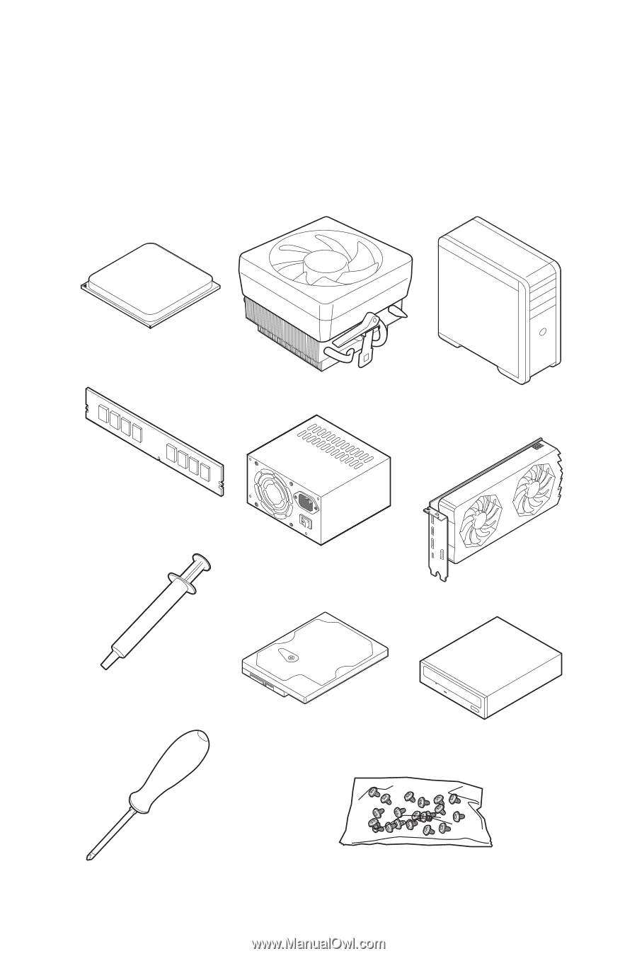
Preparing Tools and Components
DDR4 Memory
Graphics Card
SATA Hard Disk Drive
SATA DVD Drive
Phillips Screwdriver
Chassis
Power Supply Unit
A Package of Screws
Thermal Paste
CPU Fan
AMD® AM4 CPU