MSI MS-1722 User Guide
MSI MS-1722 - Whitebook ID1 - 17 Manual
 |
View all MSI MS-1722 manuals
Add to My Manuals
Save this manual to your list of manuals |
MSI MS-1722 manual content summary:
- MSI MS-1722 | User Guide - Page 1
GX720 (MS-1722)Disassemble SOP ■ 1、Battery Pack ■ 2、BOTTOM DOOR ASSY ■ 3、THERMAL-KIT And CPU Module ■ 4、RAM、WLAN And TUNER Module ■ 5、HDD Module ASSY ■ 6、ODD Module ASSY ■ 7、HINGE COVER ASSY ■ 8、UP CASE ASSY ■ 9、LOWER CASE ASSY ■ 10、LCD MODULE ASSY - MSI MS-1722 | User Guide - Page 2
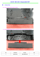
GX720(MS-1722)Disassemble SOP ■ 1、Battery Pack 1-1:Push the battery Unlock button as below; 1-2:Push the battery Release button as below, then slide the battery pack out of the slot; NO. Part Name Part No. Qty 1 Battery Pack S9N-1566210-SJ3 1 - MSI MS-1722 | User Guide - Page 3
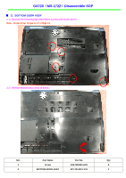
GX720(MS-1722)Disassemble SOP ■ 2、BOTTOM DOOR ASSY 2-1:Remove the following 5pcs M2.5*5mm screws with Screw Driver. Note:Screw driver torque is 2.0~2.5kgf.cm 2-2:Remove Bottom Door Assy as below; NO. Part Name Part No. Qty 1 Screw E43-I250551-H29 5 2 BOTTOM DOOR ASSY 307-721J211-Y31 1 - MSI MS-1722 | User Guide - Page 4
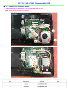
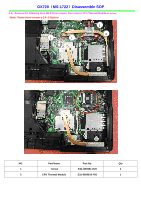
GX720(MS-1722)Disassemble SOP ■ 3、THERMAL-KIT And CPU Module 3-1:Remove 4pcs M2.5*5mm screws, CPU Fan sink Cable and CPU Fan. Note:Screw driver torque is 2.0~2.5kgf.cm Cable 3 2 1 4 NO. Part Name Part No. Qty 1 Screw E43-I250551-H29 4 2 CPU FAN E33-0800050-F05 1 - MSI MS-1722 | User Guide - Page 5
GX720(MS-1722)Disassemble SOP 3-2:Remove the following 4pcs M2.5*5mm screws, then remove CPU Thermal Module as below; Note:Screw driver torque is 2.0~2.5kgf.cm 2 4 1 3 NO. Part Name Part No. Qty 1 Screw E43-I250551-H29 4 2 CPU Thermal Module E31-0800610-F05 1 - MSI MS-1722 | User Guide - Page 6
GX720(MS-1722)Disassemble SOP 3-3:Remove 4pcs M2.5*5mm screws, Then remove MECH HEATSINK as below; Note:Screw driver torque is 2.0~2.5kgf.cm 3 1 2 4 NO. Part Name Part No. Qty 1 Screw E43-I250551-H29 4 2 MECH HEATSINK E31-0403610-F05 1 - MSI MS-1722 | User Guide - Page 7
GX720(MS-1722)Disassemble SOP 3-4: Open the CPU Slot ; 3-5:Remove CPU Module as below; NO. Part Name Part No. Qty 1 CPU Module A09-2420176-I06 1 - MSI MS-1722 | User Guide - Page 8
GX720(MS-1722)Disassemble SOP 3-6:Remove 2pcs M2.5*5mm screws, Then remove VGA Card Module as below; Note:Screw driver torque is 2.0~2.5kgf.cm NO. Part Name Part No. Qty 1 Screw E43-I250551-H29 2 2 VGA card 602-V114-01S 1 - MSI MS-1722 | User Guide - Page 9
GX720(MS-1722)Disassemble SOP ■ 4、RAM、WLAN And TUNER Module 4-1:Push the RAM locks away; 4-2:Take off the RAM Module as below: NO. Part Name Part No. Qty 1 RAM Module S7C-S346801-T10 2 - MSI MS-1722 | User Guide - Page 10
GX720(MS-1722)Disassemble SOP 4-3: Remove 1pcs M2*3mm screw, and then remove ANTENNA/HIGH-TEK/R-L as below; Note:Screw driver torque is 1.0~1.5kgf.cm 1 4-4:Remove WIRELESS CARD as below; NO. Part Name Part No. Qty 1 Screw E43-1303501-H29 1 2 WIRELESS CARD S57-0800180-I06 1 - MSI MS-1722 | User Guide - Page 11
GX720(MS-1722)Disassemble SOP 4-5:Pull out Tuner Antenna, then remove 1pcs M2*3mm Screw as below; Note:Screw driver torque is 1.0~1.5kgf.cm 1 4-6:Remove DVB-T MINI-PCIE CARD as below; NO. Part Name Part No. Qty 1 Screw E43-1303501-H29 1 2 DVB-T MINI-PCIE CARD S36-0000610-K45 1 - MSI MS-1722 | User Guide - Page 12
GX720(MS-1722)Disassemble SOP ■ 5、HDD Module ASSY 5-1:Remove 2pcs M2.5*5mm Screws , then remove HDD Door Assy as below; Note:Screw driver torque is 2.0~2.5kgf.cm 5-2:Remove HDD DOOR ASSY as below; NO. Part Name Part No. Qty 1 Screw E43-I250551-H29 2 2 HDD DOOR ASSY 307-721K211-Y31 1 - MSI MS-1722 | User Guide - Page 13
GX720(MS-1722)Disassemble SOP 5-3:Remove 2pcs M3*3.5mm Screws, then remove HDD Bracket as below; Note:Screw driver torque is 1.5~2.0kgf.cm NO. Part Name Part No. Qty 1 Screw E43-1303501-H29 2 2 HDD Bracket Assy E2M-2211511-Y28 1 3 HDD MODULE ASSY S71-2408505-W36 1 - MSI MS-1722 | User Guide - Page 14
GX720(MS-1722)Disassemble SOP ■ 6、ODD Module ASSY 6-1: Take out ODD Module Assy ; - MSI MS-1722 | User Guide - Page 15
GX720(MS-1722)Disassemble SOP 6-2:Remove ODD Bezel as below; NO. Part Name Part No. Qty 1 ODD Bezel 307-722F112-Y31 1 - MSI MS-1722 | User Guide - Page 16
GX720(MS-1722)Disassemble SOP 6-3:Remove 2pcs M2*3mm Screws, Then remove ODD Bracket as below; Note:Screw driver torque is 1.5~1.8kgf.cm NO. Part Name Part No. Qty 1 Screw E43-1203003-H29 2 2 ODD Side Bracket E2M-2211611-Y28 1 3 ODD MODULE ASSY S7D-2270001-SI4 1 - MSI MS-1722 | User Guide - Page 17
GX720(MS-1722)Disassemble SOP ■ 7、HINGE COVER ASSY 7-1:Push Fastener as below; - MSI MS-1722 | User Guide - Page 18
GX720(MS-1722)Disassemble SOP 7-2:Remove Hinge Cover as below; NO. Part Name Part No. Qty 1 HINGE COVER 307-721E211-Y31 1 - MSI MS-1722 | User Guide - Page 19
GX720(MS-1722)Disassemble SOP 7-3:Pull out LCD LVDS Cable, Then remove MICROPHONE Cable as below; 7-4:Pull out CMOS CABLE as below; NO. Part Name Part No. Qty 1 LCD LVDS Cable K19-3036005-H39 1 2 MICROPHONE S34-2100620-N44 1 3 CMOS CABLE K10-3004055-H58 1 - MSI MS-1722 | User Guide - Page 20
GX720(MS-1722)Disassemble SOP 7-5:Take the Cable out of the slot as below; - MSI MS-1722 | User Guide - Page 21
GX720(MS-1722)Disassemble SOP 7-6:Remove 3pcs M2.5*5mm Screws as below; Note:Screw driver torque is 2.0~2.5kgf.cm 7-7:Remove 3pcs M2.5*5mm Screws as below; Note:Screw driver torque is 2.0~2.5kgf.cm NO. Part Name Part No. Qty 1 Screw E43-I250551-H29 6 - MSI MS-1722 | User Guide - Page 22
GX720(MS-1722)Disassemble SOP ■ 8、UPCASE ASSY 8-1:Remove 5pcs M2*3mm Screws、Remove1pcs M2.5*5mm Screw, Then remove Keyboard as below; Note:Screw driver torque is 2.0~2.5kgf.cm 8-2:Remove Keyboard Cable as below; NO. Part Name Part No. Qty 1 Screw E43-1203003-H29 5 2 Screw E43-I250551-H29 - MSI MS-1722 | User Guide - Page 23
GX720(MS-1722)Disassemble SOP 8-3:Remove16pcs M2.5*5mm Screws as below; Note:Screw driver torque is 2.0~2.5kgf.cm NO. Part Name Part No. Qty 1 Screws E43-1250551-H29 16 - MSI MS-1722 | User Guide - Page 24
GX720(MS-1722)Disassemble SOP 8-4:Remove PCMCIA DUMMY CARD, Then remove XD CARD DUMMY as below; NO. Part Name Part No. Qty 1 PCMCIA DUMMY CARD E2P-2212814-H76 1 2 XD CARD DUMMY E2P-4211412-H76 1 - MSI MS-1722 | User Guide - Page 25
GX720(MS-1722)Disassemble SOP 8-5:Remove Touchpad FPC (connected with M/B ) as below; NO. Part Name Part No. Qty 1 Touchpad FPC (To M/B ) K1C-1026016-J36 1 - MSI MS-1722 | User Guide - Page 26
GX720(MS-1722)Disassemble SOP 8-6:Remove 3pcs M2*L3 mm Screws as below ; Note:Screw driver torque is 1.0~1.5kgf.cm NO. Part Name Part No. Qty 1 Screws E43-1203003-H29 3 - MSI MS-1722 | User Guide - Page 27
GX720(MS-1722)Disassemble SOP 8-7:Remove 4pcs M2*L3 mm Screws, Then remove SPEAKER ASSY as below; Note:Screw driver torque is1.0~1.5kgf.cm NO. Part Name Part No. Qty 1 Screws E43-1203003-H29 4 2 SPEAKER ASSY S33-A000500-F33 1 - MSI MS-1722 | User Guide - Page 28
GX720(MS-1722)Disassemble SOP 8-8: Remove 2pcs M2*3mm Screws ,Remove Touchpad FPC (To Button ), Then remove TOUCH/B as below; Note:Screw driver torque is1.0~1.5kgf.cm NO. Part Name Part No. Qty 1 Screw E43-1203003-H29 2 - MSI MS-1722 | User Guide - Page 29
GX720(MS-1722)Disassemble SOP 8-9:Remove Touch Pad Board as below; NO. Part Name Part No. Qty 1 UPPER CASE ASSY 307-722C211-Y31 1 - MSI MS-1722 | User Guide - Page 30
GX720(MS-1722)Disassemble SOP 8-10:Pull out TOUCH/B Cable as below; NO. Part Name Part No. Qty 1 TOUCH/B Cable K1C-1036001-J36 1 2 TOUCH/B 607-1722C-B10 1 8-11:Remove Touchpad FPC (To Button ) as below; NO. Part Name Part No. Qty 1 Touch Pad Board S78-3700360-SD2 1 2 Touchpad - MSI MS-1722 | User Guide - Page 31
GX720(MS-1722)Disassemble SOP ■ 9、LOWER CASE ASSY 9-1:Remove 1pcs M2.5*5mm Screw, Then remove USB Board Cable as below; Note:Screw driver torque is 2.0~2.5kgf.cm 1 NO. Part Name Part No. Qty 1 Screws E43-1250551-H29 1 - MSI MS-1722 | User Guide - Page 32
GX720(MS-1722)Disassemble SOP 9-2:Pull out Bluetooth Cable as below; NO. Part Name Part No. Qty 1 BlueTooth Cable K10-3008076-H58 1 - MSI MS-1722 | User Guide - Page 33
GX720(MS-1722)Disassemble SOP 9-3:Remove Bluetooth Antenna ,Then remove Bluetooth Cable as below; 9-4:Remove BlueTooth Board as below; NO. Part Name Part No. Qty 1 BlueTooth Board 605-6837D-070 1 - MSI MS-1722 | User Guide - Page 34
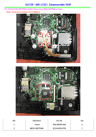
GX720(MS-1722)Disassemble SOP 9-5:Remove M/B as below; NO. Part Name Part No. Qty 1 MAIN Board 607-17221-B10 1 - MSI MS-1722 | User Guide - Page 35
GX720(MS-1722)Disassemble SOP 9-6:Remove 2pcs M2*L3 mm screws Then remove RJ11 MODEM CABLE as below; Note:Screw driver torque is 1.0~1.5kgf.cm 9-7:Remove MODEM as below; NO. Part Name Part No. Qty 1 MODEM S52-2801180-C59 1 2 Screw E43-1203003-H29 2 3 RJ11 MODEM CABLE K10-3002109-H58 - MSI MS-1722 | User Guide - Page 36
GX720(MS-1722)Disassemble SOP 9-8:Remove 1pcs M2.5*5mm Screw, Then remove USB Board as below; Note:Screw driver torque is 1.5~2.0kgf.cm 1 NO. Part Name Part No. Qty 1 Screw E43-I250551-H29 1 2 USB Board 607-1722B-B10 1 - MSI MS-1722 | User Guide - Page 37
GX720(MS-1722)Disassemble SOP 9-9:Remove SPEAKER ASSY as below; NO. Part Name Part No. Qty 1 SPEAKER ASSY S33-A000400-F33 1 - MSI MS-1722 | User Guide - Page 38
GX720(MS-1722)Disassemble SOP 9-10:Remove TV IO JACK as below; NO. Part Name Part No. Qty 1 TV IO JACK K19-3001016-H39 1 2 Low Case ASSY 307-721D211-Y31 1 - MSI MS-1722 | User Guide - Page 39
GX720(MS-1722)Disassemble SOP ■ 10、LCD MODULE ASSY 10-1:Remove 8pcs LCD Rubbers, Then remove 8pcs M2.5*5mm screws as below; Note:Screw driver torque is 2.0~2.5kgf.cm NO. Part Name Part No. Qty 1 LCD BEZEL TOP RUBBER E2Y-7210411-Y40 4 2 LCD BEZEL BOTTOM RUBBER E2Y-7210511-Y40 2 3 LCD - MSI MS-1722 | User Guide - Page 40
GX720(MS-1722)Disassemble SOP 10-2:Disassemble LCD Bezel as below ; NO. Part Name Part No. Qty 1 LCD BEZEL 307-721B211-Y31 1 - MSI MS-1722 | User Guide - Page 41
GX720(MS-1722)Disassemble SOP 10-3:Remove 2pcs M2.5*5mm screws, Then remove 3pcs magnet as below; Note:Screw driver torque is 2.0~2.5kgf.cm 10-4:Remove 6pcs M2.5*5mm screws, Then remove LCD_HINGE_R-L as below; Note:Screw driver torque is 3.0~3.5kgf.cm NO. Part Name Part No. Qty 1 Screw E43- - MSI MS-1722 | User Guide - Page 42
GX720(MS-1722)Disassemble SOP 10-5:Remove Inverter Cable as below; 10-6:Remove Inverter Module, Then remove Display Module as below; NO. Part Name Part No. Qty 1 Notebook Inverter S78-3300290-SG3 1 2 Display Module S1J-7B0A001-S02 1 - MSI MS-1722 | User Guide - Page 43
GX720(MS-1722)Disassemble SOP 10-7:Remove CMOS Cable , Then remove CMOS Camera Module as below; NO. Part Name Part No. Qty 1 CMOS Camera Module S1F-0003020-C54 1 2 CMOS Cable K10-3004055-H58 1 - MSI MS-1722 | User Guide - Page 44
GX720(MS-1722)Disassemble SOP 10-8:Remove MICROPHONE as below; NO. Part Name Part No. Qty 1 MICROPHONE S34-2100620-N44 1 2 LCD Cover Assy 307-721A211-CG0 1 - MSI MS-1722 | User Guide - Page 45
GX720(MS-1722)Disassemble SOP 10-9:Remove 3PCS WIRELISS ANTENNA as below; NO. Part Name Part No. Qty 1 WIRELISS ANTENNA S79-1800850-V03 1 2 Wireless Antenna S79-1800860-V03 1 3 Wireless Antenna S79-1800870-V03 1 - MSI MS-1722 | User Guide - Page 46
GX720(MS-1722)Disassemble SOP 10-10:Remove LCD LVDS Cable as below; NO. Part Name Part No. Qty 1 LCD LVDS Cable K19-3036005-H39 1 - MSI MS-1722 | User Guide - Page 47
GX720&MS-1722 Disassemble SOP 10-11:Remove 10pcs M2*3mm Screws, Then remove LCD Bracket as below; Note:Screw driver torque is 1.5~2.0kgf.cm NO. Part Name Part No. Qty 1 Screw E43-1203003-H29 10 2 LCD-Bracket-R E2M-7211511-Y28 1 3 LCD-Bracket-L E2M-7211411-Y28 1 4 LCD BRACKET TOP - MSI MS-1722 | User Guide - Page 48
GX720(MS-1722)screws specification Photo Screw specification Label (M2.5*L5MM) black (M2*L3MM)white - MSI MS-1722 | User Guide - Page 49
GX720(MS-1722)screws specification ■ 1、BOTTOM DOOR ASSY total 19Pcs screws, specification: Photo Screw specification (M2.5*L5mm) black label - MSI MS-1722 | User Guide - Page 50
GX720(MS-1722)screws specification ■ 2、THERMAL-KIT and WIRELESS CARD total 23Pcs screws, specification: 10 9 11 12 75 2 3 68 41 Photo Screw specification (M2.5*L5mm) black label (M2*L3mm)white - MSI MS-1722 | User Guide - Page 51
GX720(MS-1722)screws specification ■ 3、UPCASE ASSY and SPEAKER ASSY total 13Pcs screws , specification: Photo Screw specification (M2.5*L5mm) black Label (M2*L3mm)white - MSI MS-1722 | User Guide - Page 52
GX720(MS-1722)screws specification ■ 4、LCD BEZEL total 8Pcs screws, specification: Photo Screw specification (M2.5*L5mm) black label - MSI MS-1722 | User Guide - Page 53
GX720(MS-1722)screws specification ■ 5、LCD MODULE ASSY total 18Pcs screws , specification: Photo Screw specification (M2.5*L5mm) black label (M2*L3mm)white - MSI MS-1722 | User Guide - Page 54
GX720(MS-1722)screws specification ■ 6、UP CASE and LOWER CASES total 3pcs screws, specification: Photo Screw specification (M2*L3mm)white label - MSI MS-1722 | User Guide - Page 55
GX720(MS-1722)screws specification ■ 7、Touch Pad Board total 2pcs screws, specification: Photo Screw specification (M2*L3mm)white label - MSI MS-1722 | User Guide - Page 56
GX720(MS-1722)screws specification ■ 8、NB total 2pcs screws specification: Photo Screw specification (M2.5*L5mm) black label
-
 1
1 -
 2
2 -
 3
3 -
 4
4 -
 5
5 -
 6
6 -
 7
7 -
8
-
9
-
10
-
11
-
12
-
13
-
14
-
15
-
16
-
17
-
18
-
19
-
20
-
21
-
22
-
23
-
24
-
25
-
26
-
27
-
28
-
29
-
30
-
31
-
32
-
33
-
34
-
35
-
36
-
37
-
38
-
39
-
40
-
41
-
42
-
43
-
44
-
45
-
46
-
47
-
48
-
49
-
50
-
51
-
52
-
53
-
54
-
55
-
56
 |
 |

GX720
(
MS-1722
)
Disassemble SOP
■
1
、
Battery Pack
■
2
、
BOTTOM DOOR ASSY
■
3
、
THERMAL-KIT And CPU Module
■
4
、
RAM
、
WLAN And TUNER Module
■
5
、
HDD Module ASSY
■
6
、
ODD Module ASSY
■
7
、
HINGE COVER ASSY
■
8
、
UP CASE ASSY
■
9
、
LOWER CASE ASSY
■
10
、
LCD MODULE ASSY