MSI Neo4 User Guide
MSI Neo4 - K8N Platinum Motherboard Manual
 |
UPC - 816909007442
View all MSI Neo4 manuals
Add to My Manuals
Save this manual to your list of manuals |
MSI Neo4 manual content summary:
- MSI Neo4 | User Guide - Page 1
K8N Neo4 Series MS-7125 (v1.X) ATX Mainboard G52-M7125X1 i - MSI Neo4 | User Guide - Page 2
radio frequency energy and, if not installed and used in accordance with the instruction manual, may cause harmful interference to comply with the emission limits. VOIR LA NOTICE D'INSTALLATION AVANT DE RACCORDER AU RESEAU. Micro-Star International MS-7125 This device complies with Part 15 of the - MSI Neo4 | User Guide - Page 3
correctness of its contents. Our products are under continual improvement and AMD, Athlon™, Athlon™ XP, Thoroughbred™, and Duron™ are registered trademarks of AMD NVIDIA, the NVIDIA logo, DualNet, and nForce are registered trademarks or trademarks of NVIDIA nVidia nForce4 Ultra Date December 2004 iii - MSI Neo4 | User Guide - Page 4
guide, BIOS updates, driver updates, and other information: http://www.msi.com.tw & http://www.msi. com.tw/program/service/faq/faq/esc_faq_list.php h Contact our technical staff at: [email protected] Safety Instructions 1. Always read the safety instructions carefully. 2. Keep this User's Manual - MSI Neo4 | User Guide - Page 5
Guide 2-2 Central Processing Unit: CPU 2-3 CPU Installation Procedures for Socket 939 2-4 Installing AMD Port (Optional 2-12 Serial Port Connector 2-13 USB Connectors 2-13 LAN (RJ-45) Jack 2-14 ATA/Serial ATA RAID Connectors controlled by nForce4 Ultra: SATA1/SATA2/SATA3/SATA4; Serial ATA - MSI Neo4 | User Guide - Page 6
Front USB Connectors: JUSB1/JUSB2/JUSB3 2-19 Front Panel Audio Connector: JAUD1 2-20 IrDA BIOS Setup 3-1 Entering Setup ...3-2 Selecting the First Boot Device 3-2 Control Keys 3-3 Getting Help 3-3 The Main Menu 3-4 Standard CMOS Features 3-6 Advanced BIOS Features 3-8 Advanced Chipset - MSI Neo4 | User Guide - Page 7
Summary of RAID Configurations 5-2 RAID Configuration 5-3 Basic Configuration Instructions 5-3 Setting Up the NVRAID BIOS 5-3 NVIDIA RAID Untility Installation 5-7 Installing the RAID Driver (for bootable RAID Array 5-7 Installing the NVIDIA RAID Software Under Windows (for Non-bootable RAID - MSI Neo4 | User Guide - Page 8
. 6-14 Installing the RAID Driver (For bootable RAID Array 6-15 Installing Driver in Windows XP/2000/Server 2003 6-15 Installing Drivers and GUI 6-16 Chapter 7. Installation of Driver & Utility 7-1 Driver Installation 7-2 NVIDIA nForce4 System Driver 7-2 Realtek AC97 Audio Driver 7-5 Utility - MSI Neo4 | User Guide - Page 9
you for choosing the K8N Neo4 Platinum (MS-7125) v1.X ATX mainboard. The K8N Neo4 Platinum mainboard is based on nVIDIA® nForce™4 Ultra chipset for optimal system efficiency. Designed to fit the advanced AMD® K8 Athlon 64 FX / Athlon 64 processor, the K8N Neo4 Platinum mainboard delivers a high - MSI Neo4 | User Guide - Page 10
about CPU, please visit http://www.msi.com.tw/program/ products/mainboard/mbd/pro_mbd_cpu_support.php) Chipset h nVIDIA nForce4 Ultra - HyperTransport link to the AMD Athlon 64/Athlon 64 FX CPU - HyperTransport supporting speed up to 1GHz (2000MT/s) - Supports PCI Express x16/x1/x2 interface - MSI Neo4 | User Guide - Page 11
Getting Started USB Interface h 10 USB ports - Controlled by nForce4 Ultra chipset - 4 ports in the rear I/O, 6 ports via the external bracket NV RAID (Software) h Supports up to 4 SATA and 4 ATA133 Hard drives - RAID 0 or 1, 0+1, JBOD is supported - RAID function available for PATA+SATA H/D drives - MSI Neo4 | User Guide - Page 12
(DMI) function which records your mainboard specifications. h Supports boot from LAN, USB Device 1.1 & 2.0, and SATA HDD. Dimension h ATX Form Factor (30.4 cm X 24.4 cm) Mounting h 9 mounting holes MSI Reminds You... 1. Now the nVidia nForce4 system driver is only available for Windows 2000 and - MSI Neo4 | User Guide - Page 13
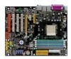
JCD1 JD B1 MSI CoreCell BATT + NForce4 Ultra Silicon Image S ATA L in k S il 3 114 CT 1 7 6 ( Op ti ona l) JU SB1 (Optional) SATA6 SATA7 SFAN2 SATA5 SATA8 JU SB2 SATA2 SATA1 SATA4 SATA3 NBFAN1 SW1 BIOS JU SB3 JLPC1 JFP2 JFP1 IDE 2 IDE 1 K8N Neo4 Platinum (MS-7125 v1.X) ATX Mainboard - MSI Neo4 | User Guide - Page 14
MS-7125 ATX Mainboard Packing Contents MSI motherboard MSI Driver/Utility CD SATA RAID Driver Diskette SATA Cable (Optional) Power Cable D-Bracket 2 (Optional) Round Cable of IDE Devices Round Cable of Floppy Disk 1394 Cable (Optional) Back IO Shield User's Guide 1-6 Test Report Quick - MSI Neo4 | User Guide - Page 15
Setup Chapter 2. Hardware Setup Hardware Setup This chapter tells you how to install the CPU, memory modules, and expansion cards, as well as how to setup the jumpers on the mainboard. Also, it provides the instructions on connecting the peripheral devices, such as the mouse, keyboard, etc. While - MSI Neo4 | User Guide - Page 16
MS-7125 ATX Mainboard Quick Components Guide Back Panel I/O, p.2-12 CPU, p.2-3 DDR DIMMs, p.2-7 JPW1, p.2-10 SFAN1, p.2-16 CPUFAN1, p.2-16 JCI1, p.2-7 ATX1, p.2-10 JIR1, p.2-20 FDD1, p.2-16 PCI_E3, p.2-26 PCI_E2, p.2-26 PCI_E1, p.2-26 - MSI Neo4 | User Guide - Page 17
first to ensure the safety of CPU. Overclocking This motherboard is designed to support overclocking. However, please make sure your components are able to tolerate such abnormal setting, while doing overclocking. Any attempt to operate beyond product specifications is not recommended. We do not - MSI Neo4 | User Guide - Page 18
MS-7125 ATX Mainboard CPU Installation Procedures for Socket 939 1. Please turn off the power and unplug the power cord before installing the CPU. 2. not be seen. Please note that any violation of the correct installation procedures may cause permanent damages to your mainboard. Gold arrow Gold - MSI Neo4 | User Guide - Page 19
Hardware Setup Installing AMD Athlon64 CPU Cooler Set When you are installing the CPU, make sure the CPU has a heat sink and a cooling fan attached on the top to prevent overheating. If you do not have the heat sink and cooling fan, contact your dealer to purchase and install them before turning on - MSI Neo4 | User Guide - Page 20
MS-7125 ATX Mainboard 5. Position the cooling set onto the re- 7. Fasten down the lever Hook 9. Attach the CPU Fan cable to the CPU fan connector on the mainboard. Fixed Lever Fixed Bolt MSI Reminds You... While disconnecting the Safety Hook from the fixed bolt, it is necessary to keep an eye on - MSI Neo4 | User Guide - Page 21
(Double In-Line Memory Module) modules and supports the memory size up to 4GB. You can install DDR266/ 333/400 modules on the DDR DIMM slots (DDR 1~4). For the updated supporting memory modules, please visit http://www.msi.com.tw/ program/products/mainboard/mbd/pro_mbd_trp_list.php. DIMM1~4 (from - MSI Neo4 | User Guide - Page 22
MS-7125 ATX Mainboard GREEN DIMM1 (Ch A) 128MB~1GB 128MB~1GB PURPLE DIMM2 (Ch B) 128MB~1GB 128MB~1GB GREEN DIMM3 (Ch A) 128MB~1GB 128MB~1GB PURPLE DIMM4 (Ch B) 128MB~1GB 128MB~1GB System Density 256MB~2GB 256MB~2GB 512MB~4GB MSI mainboard DO NOT support the memory module installed with more - MSI Neo4 | User Guide - Page 23
Hardware Setup MSI Reminds You... 1. The maximum memory speed decreases when the following two Memory Combination is selected (you can also refer to the Recommended Memory Combination list shown in the previous page: - Each channel is installed with two double-sided memory mod- ules - Both DIMM1 and - MSI Neo4 | User Guide - Page 24
MS-7125 ATX Mainboard Power Supply The mainboard supports ATX power supply for the power system. Before inserting the power supply connector, always make sure that all components are installed PIN SIGNAL 1 GND 2 GND 3 12V 4 12V MSI Reminds You... 1. These two connectors connect to the ATX - MSI Neo4 | User Guide - Page 25
under S5 (power-off) states, and the power code is plugged while installing modules. Due to several pins are very sensitive to ESD, so this kind of memory-replacement actions might cause system chipset unable to boot. Please follow the following solution to avoid this situation. Unplug the AC power - MSI Neo4 | User Guide - Page 26
MS-7125 ATX Mainboard Back Panel The back panel provides the following connectors: Mouse Parallel LAN LAN L-In RS-Out (Optional) (Optional) Keyboard COM Port 1394 Port SPDIF (Optional) Out (Coaxial) USB IEEE1394 high-speed serial bus complements USB by providing enhanced PC connectivity - MSI Neo4 | User Guide - Page 27
(Open Host Controller Interface) Universal Serial Bus roots for attaching USB devices such as keyboard, mouse or other USB-compatible devices. You can plug the USB device directly into the connector. 1 2 3 4 5 6 7 8 USB Ports USB Port Description PIN SIGNAL 1 VCC 2 -Data 0 3 +Data0 4 GND - MSI Neo4 | User Guide - Page 28
MS-7125 ATX Mainboard LAN (RJ-45) Jack (Optional) The mainboard provides 2 connector for microphones. However, there is an advanced audio application provided by Realtek ALC850 to offer support for 7.1-channel audio operation and can turn rear audio connectors from 2-channel to 4-/5.1-/7.1 channel - MSI Neo4 | User Guide - Page 29
Port Connector: LPT1 The mainboard provides a 25-pin female centronic connector as LPT. A parallel port is a standard printer port that supports Enhanced Parallel Port (EPP) and Extended Capabilities Parallel Port (ECP) mode. 13 1 25 14 Pin Definition PIN SIGNAL DESCRIPTION 1 STROBE - MSI Neo4 | User Guide - Page 30
MS-7125 ATX Mainboard Connectors The mainboard provides connectors to connect to FDD, IDE HDD, case, LAN, USB Ports, IR module and CPU/System FAN. Floppy Disk Drive Connector: FDD1 The mainboard provides a standard floppy disk drive connector that supports 360K, 720K, 1.2M, 1.44M and 2.88M floppy - MSI Neo4 | User Guide - Page 31
hard drive to Slave mode by setting the jumper accordingly. IDE2 (Secondary IDE Connector) IDE2 can also connect a Master and a Slave drive. MSI Reminds You... If you install two hard disks on cable, you must configure the second drive to Slave mode by setting its jumper. Refer to the hard disk - MSI Neo4 | User Guide - Page 32
MS-7125 ATX Mainboard Serial ATA/Serial ATA RAID Connectors controlled by nForce4 Ultra: SATA1 / SATA2 / SATA3 / SATA4; Serial ATA/Serial ATA RAID Connectors controlled by Silicon Image's SATARAID5TM: SATA5 / SATA6 / SATA7 / SATA8 (Optional) The Southbridge of this mainboard is nForce4 Ultra - MSI Neo4 | User Guide - Page 33
is compliant with Intel® Front Panel I/O Connectivity Design Guide. JFP1 Pin Definition PIN Power Power LED Switch 1 USB 2.0) Connected to JUSB1, JUSB2, or JUSB3 (the USB pinheader in YELLOW color) 5 USB0+ 7 GND 9 Key (no pin) 6 USB1+ 8 GND 10 USBOC USB 2.0 Bracket (Optional) MSI - MSI Neo4 | User Guide - Page 34
MS-7125 ATX Mainboard Front Panel Audio Connector: JAUD1 The JAUD1 front panel audio connector allows you to connect to the front panel audio and is compliant with Intel® Front Panel I/O Connectivity Design Guide channel audio signal return from front panel MSI Reminds You... If you don't want to - MSI Neo4 | User Guide - Page 35
Hardware Setup IEEE 1394 Connectors: J1394_1 (Optional) The mainboard provides another 1394 pin header that allows you to connect IEEE 1394 ports via an external IEEE1394 bracket (optional). Pin Definition 2 10 1 9 J1394_1 PIN SIGNAL PIN 1 TPA+ 2 3 Ground 4 5 TPB+ 6 7 Cable power - MSI Neo4 | User Guide - Page 36
MS-7125 ATX Mainboard D-Bracket™ 2 Connector: JDB1 The mainboard comes with a JDB1 connector for you to connect to D-Bracket™ 2. DBracket™ 2 is a USB Bracket that supports both USB1.1 & 2.0 spec. It integrates four LEDs and allows users to identify system problem through 16 various combinations of - MSI Neo4 | User Guide - Page 37
there are any problems or failures. D-Bracket™ 2 supports both USB 1.1 & 2.0 specification. D-Bracket™ 2 1 2 3 4 Red Green D-Bracket™ 2 Description System Power ON 1 2 The D-LED will hang here if the processor is damaged or 3 4 not installed properly. Early Chipset Initialization Memory - MSI Neo4 | User Guide - Page 38
MS-7125 ATX Mainboard D-Bracket™ 2 Description Processor Initialization 1 2 This type of video onboard. Then, detect and initialize the video adapter. BIOS Sign On This will start showing information about logo, processor brand name Drive and controller. Boot Attempt This will set low stack and - MSI Neo4 | User Guide - Page 39
how to change your motherboard's function through the use of button. Clear CMOS Button: SW1 There is a CMOS RAM on board that has a power supply from external battery to keep the system configuration data. With the CMOS RAM, the system can automatically boot OS every - MSI Neo4 | User Guide - Page 40
MS-7125 while PCI Express x1 supports transfer rate of 250 MB/s. PCI Express x16 slot PCI Express x1 slot PCI Express x4 slot (supports PCI-E x2 device software settings for the expansion card, such as jumpers, switches or BIOS configuration. The orange PCI slot (PCI4) also works as a communcation - MSI Neo4 | User Guide - Page 41
Hardware Setup PCI Interrupt Request Routing The IRQ, acronym of interrupt request line and pronounced I-R-Q, are hardware lines over which devices can send interrupt signals to the microprocessor. The PCI IRQ pins are typically connected to the PCI bus INT A# ~ INT D# pins as follows: PCI Slot 1 - MSI Neo4 | User Guide - Page 42
: W7125NMS V1.0B32 061704 where: 1st digit refers to BIOS maker as A=AMI(R); W=AWARD(R) 2nd - 5th digit refers to the model number. 6th digit refers to nVIDIA chipset. 7th - 8th digit refers to the customer, MS=all standard customers. V1.0 refers to the BIOS version. 061704 refers to the date this - MSI Neo4 | User Guide - Page 43
MS-7125 ATX Mainboard Entering Setup Power on the computer and the system will start you power on the system, it will still use the original first boot device to boot up. MSI Reminds You... The items under each BIOS category described in this chapter are under continuous update for better system - MSI Neo4 | User Guide - Page 44
BIOS Setup Control Keys Enter> Move to the sub-menu. If you want to return to the main menu, just press the . General Help The BIOS setup program provides a General Help screen. You can call up this screen from any menu by simply pressing . The - MSI Neo4 | User Guide - Page 45
MS-7125 ATX Mainboard The Main Menu Once you enter Phoenix-Award® BIOS CMOS Setup Utility, the Main Menu will appear on the screen. The Main Menu allows you to select from twelve setup functions and two exit - MSI Neo4 | User Guide - Page 46
Load Optimized Defaults Use this menu to load the BIOS values for the best system performance, but the system stability may be affected. BIOS Setting Password Use this menu to set the password for BIOS. Save & Exit Setup Save changes to CMOS and exit setup. Exit Without Saving Abandon all changes - MSI Neo4 | User Guide - Page 47
MS-7125 . day Day of the week, from Sun to Sat, determined by BIOS. Read-only. month The month from Jan. through Dec. date The date from >. IDE Primary/Secondary Master/Slave Press PgUp/ or PgDn/ to select [Manual], [None] or [Auto] type. Note that the specifications of your drive - MSI Neo4 | User Guide - Page 48
installed. Available options: [None], [360K, 5.25 in.], [1.2M, 5.25 in.], [720K, 3.5 in.], [1.44M, 3.5 in.], [2.88M, 3.5 in.]. Halt On The setting determines whether the system will stop if an error is detected at boot : CPU Type/BIOS Version/System Memory/Total Memory The items show the CPU type - MSI Neo4 | User Guide - Page 49
MS-7125 ATX Mainboard Advanced BIOS Features Quick Boot Setting the item to [Enabled] allows the system to boot within 5 seconds since it will skip some check items. Available options: [Enabled], [Disabled]. Boot with PC2001 design guide, the system is the MPS version supported by your operating - MSI Neo4 | User Guide - Page 50
to set the sequence of boot devices where BIOS attempts to load the disk operating system. Boot Other Device Setting the option to [Enabled] allows the system to try to boot from other device if the system fails to boot from the 1st/2nd/3rd boot device. Hard Disk Boot Priority Press to enter - MSI Neo4 | User Guide - Page 51
MS-7125 ATX Mainboard Advanced Chipset Features DRAM Configuration Press to enter the sub-menu and the following screen appears: Timing Mode This field has the capacity to automatically detect all of the DRAM timing. If you set this field to [Manual], the following fields will be selectable. - MSI Neo4 | User Guide - Page 52
BIOS Setup CAS# Latency (Tcl) When the Timing Mode is set to [Manual], the field is adjustable.This controls the may be incomplete and DRAM may fail to retain data. This item applies only when synchronous DRAM is installed in the system. Available settings: [Auto], [2T], [3T], [4T], [5T], [6T], [ - MSI Neo4 | User Guide - Page 53
MS-7125 ATX Mainboard 3-12 Row to Row delay (Trrd) When the Timing Mode is set to [Manual], the field is adjustable. Specifies the active-to-active delay of different banks. Available settings: [Auto], [2T], [3T], [4T]. Write recovery time (Twr) When the Timing Mode is set to [Manual], the field - MSI Neo4 | User Guide - Page 54
set to [Manual], the field is adjustable. The time prior to the max-read DQS-return when the DQS receiver should be turned on. This is specified in units of 0.5ns. The controller needs to know when to enbale its DQS receiver in anticipation of the DRAM DQS driver truning on for - MSI Neo4 | User Guide - Page 55
MS-7125 ATX Mainboard Integrated Peripherals USB Controller This setting allows you to enable/disable the onboard USB controller. Selecting [V1.1+V2.0] enables the system to support both USB 1.1 and 2.0 spec. Setting options: [Disabled], [V1.1], [V1.1+V2.0]. USB KB/Storage Support Select [Enabled] - MSI Neo4 | User Guide - Page 56
on the system board and you wish to use it. If you install add-on FDC or the system has no floppy drive, select [Disabled] in this field. The settings are: [Enabled], [Disabled]. COM Port 1 Select an address and corresponding interrupt for the first serial port. The settings are: [3F8/IRQ4 - MSI Neo4 | User Guide - Page 57
MS-7125 Rx2Tx2]. Parallel Port There is a built-in parallel port on the on-board Super I/O chipset that provides Standard, ECP, and EPP features. It has the following Choosing [ECP + EPP] will allow the onboard parallel port to support both the ECP and EPP modes simultaneously. Choose [Normal] to - MSI Neo4 | User Guide - Page 58
IDE channels. Choose [Enabled] to activate each channel separately. Settings: [Enabled], [Disabled]. both support Ultra DMA/33, Ultra DMA/66 and Ultra DMA/100 select Auto to enable BIOS support. The settings are: [Auto], [Disabled]. OnChip IDE Channel 1 The integrated peripheral controller contains - MSI Neo4 | User Guide - Page 59
MS-7125 ATX Mainboard IR Function Select This setting allows you to specify the operation mode for serial port 2. Setting options: [IrDA], [ASKIR], [Disable]. [Disable] RS-232C - MSI Neo4 | User Guide - Page 60
BIOS Setup MSI Reminds You... S3-related functions described in this section are available only when your BIOS supports S3 sleep mode. ACPI Standby State This item specifies the power saving modes for ACPI function. If your operating system supports lost (CPU or chipset) and hardware maintains all - MSI Neo4 | User Guide - Page 61
MS-7125 ATX Mainboard Power Button Function This feature sets the function of the : [Enabled], [Disabled]. Resume By RTC Alarm The field is used to enable or disable the feature of booting up the system on a scheduled time/date. Settings: [Enabled], [Disabled]. Date The field specifies the date - MSI Neo4 | User Guide - Page 62
Controlled By The Award Plug and Play BIOS has the capacity to automatically configure all of the boot and Plug and Play compatible devices. settings are: [Auto (ESCD)], [Manual]. IRQ Resources The items are adjustable only when Resources Controlled By is set to [Manual]. Press and you will - MSI Neo4 | User Guide - Page 63
MS-7125 ATX Mainboard ** PCI Express relative items ** Maximum Payload Size This item allows you to set the PCI Express Maximum payload size per time . Settings: [4096], [128], [256], [512], [1024], [2048]. MSI the system will interrupt itself and perform the service required by the I/O device. 3-22 - MSI Neo4 | User Guide - Page 64
BIOS Setup H/W Monitor This section shows the status of your CPU, fan, overall system status, etc. Monitor function is available only if there is hardware monitoring - MSI Neo4 | User Guide - Page 65
MS-7125 ATX Mainboard Cell Menu The items in Cell Menu includes some important settings of CPU, AGP, DRAM and overclocking functions. MSI Reminds You... Change these settings only if you are familiar with the chipset. Current CPU / DDR Clock These two items show the current clocks of CPU & DDR. Read - MSI Neo4 | User Guide - Page 66
the CPU frequency by 7%. 5th level of overclocking, increasing the CPU frequency by 9%. 6th level of overclocking, increasing the CPU frequency by 11%. MSI Reminds You... Even though the Dynamic Overclocking Technology is more stable than manual overclocking, basically, it is still risky. We - MSI Neo4 | User Guide - Page 67
MS-7125 ATX Mainboard SATA Spread Spectrum This setting is used to enable or disable the SATA Spread Spectrum feature. Setting options: [Disabled], [Down Spread]. PCIE Spread Spectrum This setting is used to enable or disable the CPU Spread Spectrum feature. When overclocking the CPU, always set it - MSI Neo4 | User Guide - Page 68
BIOS Setup Adjust CPU Ratio This item lets you adjust the CPU ratio. [2.50V]~[2.85V]. NF4 Voltage NV4 voltage is adjustable in the field. Setting options are: [1.50V]~[1.85V]. MSI Reminds You... The settings shown in different color in CPU Voltage, Memory Voltage and NF4 Voltage help to verify - MSI Neo4 | User Guide - Page 69
MS-7125 ATX Mainboard Optimized Defaults The two options on the main menu allow users to restore all of the BIOS settings to the default Optimized mainboard. The Fail-Safe Defaults are the default values set by the BIOS vendor for stable system performance. When you select Load Optimized Defaults, a - MSI Neo4 | User Guide - Page 70
BIOS Setup BIOS Setting Password When you select this function, a message as below will message will show up confirming the password will be disabled. Once the password is disabled, the system will boot and you can enter Setup without entering any password. When a password has been set, you will be - MSI Neo4 | User Guide - Page 71
to activate the MSI well-known features, Live Update and Core Center, which makes it easier to update the BIOS/drivers online, and to monitor the system hard- ware status (CPU/Fan temperature and speed) or to overclock the CPU/ memory. Once you have your DigiCell installed (locate the setup - MSI Neo4 | User Guide - Page 72
://www.msi.com.tw. Quick Guide Click on this button and the quick guide of DigiCell will be displayed for you to review. H/W Diagnostic In this sub-menu, it provides the information of each DigiCell button for you to check if the representing peripherals/cards/drivers are correctly installed. Comm - MSI Neo4 | User Guide - Page 73
BIOS and drivers online. Core Center You can take advantage of Core Center to monitor the health status of your system and to overclock under Windows OS if your system supports overclocking -on, power-off and restarting features. MSI Reminds You... Click on back button in every sub-menu and it will - MSI Neo4 | User Guide - Page 74
In the H/W Diagnostic sub-menu, you can see the information, status and note of each DigiCell. You may double check the connection and installation of the item marked as gray. You may also click on the Mail to MSI button to send your questions or suggestions to MSI's technical support staff. 4-4 - MSI Neo4 | User Guide - Page 75
DigiCell Communication In the Communication sub-menu, you can see the status of all the LAN / WLAN / Bluetooth on the screen if the hardware is installed. The first icon indicates the onboard LAN on your system, the second icon indicates the wireless LAN status, and the third one is the information - MSI Neo4 | User Guide - Page 76
MS-712M5SAI TFXeaMtuarienboard Software Access Point In the Software Access Point sub-menu, you can see the communication status on your system and choose the desired - MSI Neo4 | User Guide - Page 77
office, usually the LAN card will automatically get the IP this computer uses. In this case you don't have to enable this function. SSID Means Service Set Identifier, a unique name shared among all points in a wireless network. It must be identical for all points in the network. Then the card will - MSI Neo4 | User Guide - Page 78
MS-712M5SAI TFXeaMtuarienboard enable this feature, only PCs with MAC address located in Association Control List can connect to the wireless LAN. MAC Address MAC stands - MSI Neo4 | User Guide - Page 79
/OSD/Utility online so that you don't need to search for the correct BIOS/driver version throughout the whole Web site. To use the function, you need to install the "MSI Live Update 3" application. After the installation, the "MSI Live Update 3" icon (as shown on the right) will appear on the screen - MSI Neo4 | User Guide - Page 80
MS-712M5SAI TFXeaMtuarienboard MEGA STICK In the MEGA STICK sub-menu, you can configure the settings of MSI MEGA STICK and the media files (*.m3u, *.mp3, *.wav, *.cda, *.wma) on your system. Basic Function Here you can edit your own play list with the buttons "load", "save", "delete", "shuttle", " - MSI Neo4 | User Guide - Page 81
Introduction to DigiCell There is also a toolbar for you to execute some basic function, like play, stop, pause, previous/next song, song info and volume adjust. There is also a scroll bar on the top for you to forward/rewind. previous pause next forward/rewind bar stop play song's - MSI Neo4 | User Guide - Page 82
MS-712M5SAI TFXeaMtuarienboard Non-Unicode programs supported If you are using an operating system that the file names display incorrectly. However, you can install the Supplemental Language Support provided by Microsoft to solve this problem. You need to have your Microsoft Setup CD prepared in - MSI Neo4 | User Guide - Page 83
the [Advanced] tab and select the language you want to be supported (the language of the filename in the MegaStick) from the dropdown list in the [Language for non-Unicode programs], then click [Apply]. The system will install the necessary components from your Microsoft Setup CD immediately. 4-13 - MSI Neo4 | User Guide - Page 84
MS-712M5SAI TFXeaMtuarienboard Core Center (for AMD K8 Processor) Click on the Core Center icon in the main menu and the Core Center in the left and right sides, two sub-menus will open for users to overclock, overspec or to adjust the thresholds of system to send out the warning messages. 4-14 - MSI Neo4 | User Guide - Page 85
Cool'n'Quiet, the system will automatically configure an optimal setting for you. MSI Reminds You... To ensure that Cool'n'Quiet function is activated and will be to double confirm that: 1. Run BIOS Setup, and se- lect Cell Menu. Under Cell Menu, find Cool'n'Quiet Support, and set this item to " - MSI Neo4 | User Guide - Page 86
MS-712M5SAI TFXeaMtuarienboard Audio Speaker Setting In the Audio Speaker Setting sub-menu, you can configure the multi-channel audio operation, perform speaker test, and choose - MSI Neo4 | User Guide - Page 87
Introduction to DigiCell Click on the "Speaker test" button and the following dialogue box will appear: In this Speaker Configuration dialogue box, select the audio configuration which is identical to the audio jack on your mainboard. Once the correct audio configuration is selected, click "Apply" - MSI Neo4 | User Guide - Page 88
MS-712M5SAI TFXeaMtuarienboard Power on Agent In the Power on Agent sub-menu, you can configure "OK" to restart the computer right away or click "Later" to restart your computer later. MSI Reminds You... Please note that the new setting will not take effect until you restart your computer. 4-18 - MSI Neo4 | User Guide - Page 89
use the button "-Delete" to remove the added programs, or you can right-click on the selected program and click Delete. delete the added program MSI Reminds You... You can also enable the Every turn on function, which will enable the specified program(s) and file(s) every time the Digi Cell - MSI Neo4 | User Guide - Page 90
MS office, and you need to enter your user name & password everytime when you boot up your computer. 2. If there are multi users using the same computer this setting if you want to use the Auto Login feature. It supports the following operating systems: Win9X, Windows ME, Windows 2000 & Windows XP - MSI Neo4 | User Guide - Page 91
RAID Introduction Chapter 5. nVidia RAID Introduction nVidia RAID Introduction NVIDIA brings Redundant Array of Independent Disks (RAID) technology-which is used by the world's leading businesses-to the common PC desktop. This technology uses multiple - MSI Neo4 | User Guide - Page 92
MS-7125 ATX Mainboard Introduction System Requirement Operating System Support NVRAID supports the following operating systems: Windows XP Home Edition Windows XP Professional Edition Windows 2000 Professional RAID Arrays NVRAID supports MSI Reminds You... Please note that users cannot install - MSI Neo4 | User Guide - Page 93
or Spanning (JBOD) and create the desired RAID array. 3. Boot from the Windows CD, use the floppy disk that has the RAID driver to copy and install the nForce RAID software. (Check p.5-9 for details.) 4. Initialize the NVRAID Array Disks. Setting Up the NVRAID BIOS Be sure to enable the IDE RAID or - MSI Neo4 | User Guide - Page 94
MS-7125 ATX Mainboard Understanding the "Define a New Array" Window Use the Define a New Array Channel 1, controller 1, Master 2.0.M Channel 2, controller 0, Master 2.1.M Channel 2, controller 1, Master MSI Reminds You... There is no such thing as Slave drive in Serial ATA. All drives are - MSI Neo4 | User Guide - Page 95
nVIDIA RAID Introduction Using the Define a New Array Window If necessary, press between [4 KB] and [128 KB]. • Assigning the Disks The disks that you enabled from the RAID Config BIOS setup page appear in the Free Disks block. These are the drives that are available for use as RAID array disks. To - MSI Neo4 | User Guide - Page 96
MS-7125 ATX Mainboard Completing the RAID BIOS as RAID drives. The Array List window appears, where you can review the RAID arrays that you have set up. 3. Use the arrow RAID BIOS, the next step is to configure and load NVRAID drivers under Windows, as explained in "Installing the NVIDIA RAID Software Under - MSI Neo4 | User Guide - Page 97
nVIDIA RAID Introduction NVIDIA RAID Utility Installation Installing the RAID Driver (for bootable RAID Array) 1. After you complete the RAID BIOS setup, boot from the Windows CD, and the Windows Setup program starts. 2. Press F6 and wait for the Windows Setup screen to appear. 3. Specify the NVIDIA - MSI Neo4 | User Guide - Page 98
MS-7125 ATX Mainboard 4. Press Enter to continue with Windows XP Installation. Be sure to leave the floppy disk inserted in the floppy drive until the blue screen portion of Windows XP installation is completed, then take out the floppy. 5. Follow the instructions on how to install Windows XP. - MSI Neo4 | User Guide - Page 99
the RAID software. 1. Start the nForce Setup program to open the NVIDIA Windows nForce Drivers page. 2. Select the modules that you want to install. Make sure that the "NVIDIA IDE Driver" is selected. 3. Click Next and then follow the instructions. 4. After the installation is completed, be sure to - MSI Neo4 | User Guide - Page 100
MS-7125 ATX Mainboard Initializing and Using the Disk Array The RAID array is now ready to be initialized under Windows. 1. Launch Computer Management by clicking "Start" --> " - MSI Neo4 | User Guide - Page 101
nVIDIA RAID Introduction 5. Check the disk in the list if you want to make the array a dynamic disk, then click Next. The Completing the Initialize and - MSI Neo4 | User Guide - Page 102
MS-7125 ATX Mainboard RAID Drives Management There is an application called NVRAIDMAN which helps you perform the following tasks of nVDIA RAID. • Viewing RAID Array Configurations View an array configuration (mirrored, striped, mirror-striped, JBOD, or any supported combination) • Setting Up a - MSI Neo4 | User Guide - Page 103
nVIDIA RAID Introduction NVRAID Striped Array The figure below shows an example of a two hard drive striped array using identical 55.90 GB IDE hard drives ( - MSI Neo4 | User Guide - Page 104
MS-7125 ATX Mainboard Setting Up a Spare RAID Disk You can designate a hard drive to be used as a spare drive for a RAID 1 or RAID 0+1 array2. The spare drive can take over for a failed disk. NVRAID supports RAID BIOS and make sure that the drive is not part of any array (if one exists). 3. Boot into - MSI Neo4 | User Guide - Page 105
make sure that the drive that you want to mark as free is RAID enabled. 2. Enter the RAID BIOS and make sure that the drive is not part of any array (if one exists). 3. Boot into Windows and run the NVRAIDMAN program. The drive appears under the Free Disk section. Step 2: Dedicate - MSI Neo4 | User Guide - Page 106
MS-7125 ATX Mainboard 3. Click Next. The RAID Array Selection page appears. 4. From the RAID Array Selection page, select one of the arrays from the list. This is the array to which you want to allocate the dedicated free disk. 5. Click Next. The Completing the NVIDIA Spare Disk Allocation page - MSI Neo4 | User Guide - Page 107
nVIDIA RAID Introduction Method 2: Select an array and then assign a free disk to the menu to launch the Spare Disk Allocation Wizard. 3. Click Next. The Free Disk Selection page appears. 4. From the Free Disk Selection page, select one of the disks from the list. Please note that there can be more - MSI Neo4 | User Guide - Page 108
MS-7125 ATX Mainboard 5. Click Next. The Completing the NVIDIA Spare Disk Allocation page appears. 6. Click Finish. You have now assigned a dedicated free disk to a mirrored array. Once a dedicated disk has been assigned to a particular array, it can be - MSI Neo4 | User Guide - Page 109
nVIDIA RAID Introduction Example of Dedicating a Free Disk in a RAID 1 or RAID 0+1 Array click Designate Spare to launch the Spare Disk Allocation Wizard. 2. Click Designate Spare and then follow the instructions in the Wizard. The figure below shows an example of a RAID 1 array that has one spare - MSI Neo4 | User Guide - Page 110
MS-7125 ATX Mainboard Rebuilding a RAID This only applies to RAID 1 array as well as a RAID 0+1 array. Rebuilding Instructions After creating a mirrored array, you can rebuild the array using the following steps: 1. the popup menu, click Rebuild Array. The NVIDIA Rebuild Array Wizard appears. 5-20 - MSI Neo4 | User Guide - Page 111
. 5. Select the drive that you want to rebuild by clicking it from the list, then click Next. The Completing the NVIDIA Rebuild Array page appears. 6. Click Finish. The array rebuilding starts after a few seconds, and a small pop-up message appears towards the bottom right corner of the screen - MSI Neo4 | User Guide - Page 112
MS-7125 ATX Mainboard More About Rebuilding Arrays • Rebuilding Occurs in the Background The rebuilding process is very slow (it can take up to a day) and occurs - MSI Neo4 | User Guide - Page 113
SATARAID5TM Introduction Chapter 5. nVidia RAID Introduction Silicon Image the industry's leading PCI-to-SATA host controller products. Two major challenges facing the storage industry host controller and SATARAID5, both of these problems are solved. SATARAID5 software provides a Graphical User - MSI Neo4 | User Guide - Page 114
MS-7125 ATX Mainboard Introduction RAID - Redundant Array of Independent Disks RAID technology manages multiple disk drives to enhance I/O performance and provide redundancy in order to withstand - MSI Neo4 | User Guide - Page 115
for protection and is the preferred method to reduce the cost per megabyte for larger installations. Mirroring requires 100% increase in capacity to protect the data whereas the above example disk drive or a segment of a single disk drive. For home edition, JBOD function only supports one disk. 6-3 - MSI Neo4 | User Guide - Page 116
MS-7125 ATX Mainboard SATARAID5 Features h RAID 0, RAID 1, RAID 5, RAID 10, and JBOD Groups are supported. h Supported OS: Win2000/XP/Server 2003. h RAID Groups can be created and deleted without exiting Windows. h Hot Spare and On-line Rebuilding. The spare policy supports Supports Auto and Manual - MSI Neo4 | User Guide - Page 117
by the SATARAID5 GUI. During boot up, a screen similar to that below will appear for about 5 seconds. Press CTRL+S or the F4 key to enter the BIOS RAID utility. The RAID Utility menu screen will be displayed. A brief description of each section is presented on the next page. Main Menu The Main Menu - MSI Neo4 | User Guide - Page 118
MS-7125 ATX Mainboard Create to the SATA host adapter. These operations are detailed in the pages that follow. Help Window This window displays context-sensitive help and RAID sets and JBOD drives reported to the system BIOS. The lower part lists spare drives, reserved drives, conflict drives, and - MSI Neo4 | User Guide - Page 119
Groups As previously discussed, the Silicon Image SATA host adapter supports RAID 0, 1, 5, 10, and JBOD configurations. The sets very simple. They can be created either automatically or to allow the greatest flexibility, manually. 1. Select "Create RAID set" 2. Choose a RAID 0 Striped, a RAID - MSI Neo4 | User Guide - Page 120
MS-7125 ATX Mainboard 4. If manual configuration is selected, the chunk size of Striped Sets can be selected. 5. If auto configuration is selected, BIOS will select hard drives. Creating Spare Drive If there is a RAID 1 set, spare driver can be created. The spare drive can be allocated to the RAID 1 - MSI Neo4 | User Guide - Page 121
to proceed with the spare drive creation. Creating JBOD Since BIOS no longer reports non-RAID drives to the system BIOS, if a non-RAID boot drive or data drive is desired, a JBOD can be created so BIOS will report it to the system BIOS. 1. To create a JBOD, Select "Create RAID set" 2. Select "JBOD - MSI Neo4 | User Guide - Page 122
MS-7125 ATX Mainboard Rebuild RAID 1 Set This menu selection is used to initiate the copying of data from an existing drive to a replacement drive that has been installed in a RAID 1 set after the failure of one of the members. 1. Select "Rebuild RAID 1 set" 2. Select the desired set and press Enter - MSI Neo4 | User Guide - Page 123
Silicon Image SATARAID5TM Introduction 2. Select the "Conflict" entry in the Logical Drive Status window and press Enter. 6-11 - MSI Neo4 | User Guide - Page 124
MS-7125 ATX Mainboard 3. Note that some conflict resolutions may result in the drive letter assignment changing; for example the RAID set may have been drive D: but - MSI Neo4 | User Guide - Page 125
Silicon Image SATARAID5TM Introduction Low Level Formatting The Low Level Format menu selection allows the complete erasure of data on a hard drive. This is not an action, which typically needs to be performed as formatting the drive under Windows is usually sufficient to prepare the drive for use. - MSI Neo4 | User Guide - Page 126
MS-7125 ATX Mainboard Reserved Drive and Setting Size for RAID Set, Spare Drive, or JBOD Once a physical drive has been used to create a RAID set, spare drive, or JBOD by BIOS utility, BIOS saves user selected set or drive size in the reserved area of the physical drive. There is no way to remove - MSI Neo4 | User Guide - Page 127
. You may make the Serial ATA RAID driver by yourself by following the instruction below. 1. Insert the MSI CD into the CD-ROM drive. 2. Ignore the Setup screen and use "Explorer" to browse the CD. 3. Copy all the contents (including the sub-folders) in the \\nVidia\IDE\Silicon_Image\3114\Floppy to - MSI Neo4 | User Guide - Page 128
MS-7125 ATX Mainboard Installing Drivers and GUI Before installing the SATARAID5 software, Silicon Image Serial ATA host adapter driver must be installed. Insert MSI driver CD into the computer's CDROM drive and select Silicon Image SATA RAID Drivers. The Java 2 Runtime Environment is required for - MSI Neo4 | User Guide - Page 129
acceptance the license agreement, select I accept the terms of this license agreement and click Next. Choose the Typical setup type and click Next. When the installation completes, click Finish. Restart the computer when prompted. 6-17 - MSI Neo4 | User Guide - Page 130
Installation of Drivers and Utility Chapter 6. Installation of Driver & Utility Installation of Drivers & Utility MSI provides a setup CD along with your mainboard, which contains the required drivers for your system, and many other useful and powerful utility to bring you the best experience for - MSI Neo4 | User Guide - Page 131
MS-7125 ATX Mainboard Driver Installation Click on the Driver tab and the screen below will display. Click on the driver you like to install, and follow the proceeding instructions. NVIDIA nForce4 System Driver This driver is only available for Windows 2000 and Windows XP operating system. Please - MSI Neo4 | User Guide - Page 132
. All the components shown here will be selected to be installed by default. Then click Next. 3. The system will start installing the selected driver components automatically. 4. Then the following screen displays the information for the NVIDIA IDE SW Driver installation. Click Next to continue. 7-3 - MSI Neo4 | User Guide - Page 133
MS-7125 ATX Mainboard 5. Then the following screen displays the installation of NVIDIA IDE SW Driver. Click Yes to continue. 6. The following screen indicates that the installation is complete. Click Yes to restart your computer or click No to restart it later. MSI Reminds You... The installation of - MSI Neo4 | User Guide - Page 134
and Utility Realtek AC97 Audio Driver 1. Click on this button to install the Realtek AC97 Audio Driver. Then the welcome dialogue will display. Click Next to continue. The installation process will launch automatically. 2. The following screen indicates the installation is complete. Click Yes to - MSI Neo4 | User Guide - Page 135
MS-7125 ATX Mainboard Utility Installation Click on the Utility tab and the screen below will display. Click on the utility you like to install, and follow the proceeding instructions. 7-6
-
 1
1 -
 2
2 -
 3
3 -
 4
4 -
 5
5 -
 6
6 -
 7
7 -
8
-
9
-
10
-
11
-
12
-
13
-
14
-
15
-
16
-
17
-
18
-
19
-
20
-
21
-
22
-
23
-
24
-
25
-
26
-
27
-
28
-
29
-
30
-
31
-
32
-
33
-
34
-
35
-
36
-
37
-
38
-
39
-
40
-
41
-
42
-
43
-
44
-
45
-
46
-
47
-
48
-
49
-
50
-
51
-
52
-
53
-
54
-
55
-
56
-
57
-
58
-
59
-
60
-
61
-
62
-
63
-
64
-
65
-
66
-
67
-
68
-
69
-
70
-
71
-
72
-
73
-
74
-
75
-
76
-
77
-
78
-
79
-
80
-
81
-
82
-
83
-
84
-
85
-
86
-
87
-
88
-
89
-
90
-
91
-
92
-
93
-
94
-
95
-
96
-
97
-
98
-
99
-
100
-
101
-
102
-
103
-
104
-
105
-
106
-
107
-
108
-
109
-
110
-
111
-
112
-
113
-
114
-
115
-
116
-
117
-
118
-
119
-
120
-
121
-
122
-
123
-
124
-
125
-
126
-
127
-
128
-
129
-
130
-
131
-
132
-
133
-
134
-
135
 |
 |

MS-7125 (v1.X) ATX Mainboard
K8N Neo4 Series
G52-M7125X1