MSI P35 User Guide
MSI P35 Manual
 |
View all MSI P35 manuals
Add to My Manuals
Save this manual to your list of manuals |
MSI P35 manual content summary:
- MSI P35 | User Guide - Page 1
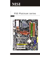
P35 Platinum series MS-7345 (v1.X) Mainboard i - MSI P35 | User Guide - Page 2
V1.0 V1.1 Revision History First release for G33 First release for P35 Date March 2007 March 2007 Technical Support If a problem arises with your system and no solution can be obtained from the user's manual, please contact your place of purchase or local distributor. Alternatively, please - MSI P35 | User Guide - Page 3
1. Always read the safety instructions carefully. 2. Keep this User's Manual for future reference. 3. Keep this . 11. If any of the following situations arises, get the equipment checked by a service personnel: † The power cord or plug is damaged. † Liquid has penetrated into the equipment - MSI P35 | User Guide - Page 4
energy and, if not installed and used in accordance with the instructions, may cause harmful interference to radio communications. However, there is compliance could void the user's authority to operate the equipment. Notice 2 Shielded interface cables and A.C. power cord, if any, must be used in - MSI P35 | User Guide - Page 5
WEEE (Waste Electrical and Electronic Equipment) Statement v - MSI P35 | User Guide - Page 6
vi - MSI P35 | User Guide - Page 7
vii - MSI P35 | User Guide - Page 8
Support ...ii Safety Instructions Guide 2-2 CPU (Central Processing Unit 2-2 Memory ...2-7 Power Supply ...2-8 Back Panel ...2-11 Connectors ...2-12 Jumper ...2-19 Button ...2-20 Slots ...2-21 LED Status Indicators 2-23 Chapter 3 BIOS / Optimized Defaults 3-26 BIOS Setting Password 3-27 Appendix - MSI P35 | User Guide - Page 9
DOT (Dynamic OverClocking B-5 Clock ...B-6 Voltage ...B-7 FAN Speed ...B-8 Temperature ...B-9 User Profile ...B-10 Appendix C Intel ICH9R SATA RAID C-1 ICH9R Introduction C-2 BIOS Configuration C-3 Installing Driver ...C-9 Installing Software C-11 RAID Migration Instructions C-15 Degraded - MSI P35 | User Guide - Page 10
Getting Started Chapter 1 Getting Started Thank you for choosing the P35 Platinum Series (MS7345 v1.X) ATX mainboard. The P35 Platinum Series mainboards are based on Intel® P35 & ICH9R chipsets for optimal system efficiency. Designed to fit the advanced Intel® Core 2 Quad/Core 2 Duo/Pentium/ Celeron - MSI P35 | User Guide - Page 11
about CPU, please visit http://global. m si. c om . t w / index. php?func =c puform ) Supported FSB - 1333/ 1066/ 800 MHz Chipset - North Bridge: Intel® P35 chipset - South Bridge: Intel® ICH9R chipset Memory Support - DDR2 800/667 SDRAM (8GB Max) - 4 DDR2 DIMMs (240pin / 1.8V) (For more information - MSI P35 | User Guide - Page 12
panel - 1 PS/2 mouse port - 1 PS/2 keyboard port - 2 eSATA ports (support Command Based Port Multipliers) - 6 USB 2.0 Ports - 1 LAN jack (10/100/ 2 PCI Express x1 slots - 1 PCI Express x4 slot - 2 PCI slots - Support 3.3V/ 5V PCI bus Interface Form Factor - ATX (30.5cm X 24.5cm) Mounting - 9 - MSI P35 | User Guide - Page 13
T:RS -Out M:CS -Out B:SS-Out POWER1 JPWR1 SYSFAN1 SYSFAN4 PCI_E3 P CI _E 1 Intel P35 SYSFAN3 DI MM _B1 DI MM _B2 DI MM _A1 DI MM _A2 SATA3 SATA4 IC IHn9tRel JB1 JB2 (optional) JUSB3 JUSB2 J1394_1(optional) JFP1 JUSB1 SATA6 SATA5 P35 Platinum Series (MS-7345 v1.X) ATX Mainboard 1-4 - MSI P35 | User Guide - Page 14
Packing Checklist Getting Started MSI motherboard MSI Driver/Utility CD Back IO Shield Power Cable SATA Cable IDE Cable Floppy Cable external SATA Cable (Optional) 1394 Bracket (Optional) User's Guide and Quick Guide ATX Extender (Optional) * The pictures are for reference only and may - MSI P35 | User Guide - Page 15
Hardware Setup Chapter 2 Hardware Setup This chapter provides you with the information about hardware setup procedures. While doing the installation, be careful in holding the components and follow the installation procedures. For some components, if you install in the wrong orientation, the - MSI P35 | User Guide - Page 16
MS-7345 Mainboard Quick Components Guide JPWR1, p.2-9 POWER1, p.2-9 CPU, p.2-3 CPUFAN, SYSFAN5, p.2-14 p.2-14 Back Panel, p.2-10 SYSFAN1, p.2-14 SYSFAN4, p.2-14 PCI_E, p.2-21 JCOM1, p.2-18 PCI, p.2-21 DDR2, p.2-7 ATX1, p.2-9 SYSFAN3, p.2-14 JB1, - MSI P35 | User Guide - Page 17
always turn off the ATX power supply or unplug the power supply's power cord from the grounded outlet first to ensure the safety of CPU. Overclocking This mainboard is designed to support overclocking. However, please make sure your components are able to tolerate such abnormal setting, while doing - MSI P35 | User Guide - Page 18
MS-7345 Mainboard CPU & Cooler Installation W hen you are installing the CPU, make sure the CPU has a cooler attached on the top to prevent overheating. Meanwhile, do not forget to apply some thermal paste on CPU before installing the heat sink/cooler fan for better heat dispersion. Follow the - MSI P35 | User Guide - Page 19
Hardware Setup 5. Lift the load lever up and open the load plate. 6. After confirming the CPU direction for correct mating, put down the CPU in the socket housing frame. Be sure to grasp on the edge of the CPU base. Note that the alignment keys are matched. alignment key 7. Visually inspect if - MSI P35 | User Guide - Page 20
h ook s . 12. Turn over the mainboard to confirm that the clip-ends are correctly inserted. locking switch Important 1. Read the CPU status in BIOS (Chapter 3). 2. Whenever CPU is not installed, always protect your CPU socket pin with the plastic cap covered (shown in Figure 1) to avoid damaging - MSI P35 | User Guide - Page 21
Hardware Setup Memory These DIMM slots are used for installing memory modules. DDR2 240-pin, 1.8V 64x2=128 pin 56x2=112 pin Single-Channel: All DIMMs in GREEN Dual-Channel: Channel A in GREEN; Channel B in ORANGE Dual-Channel mode Population Rule In Dual-Channel mode, the memory modules can - MSI P35 | User Guide - Page 22
MS-7345 Mainboard Installing Memory Modules 1. The memory module has only one notch on the center and will only fit in the right orientation. 2. Insert the memory module vertically into the DIMM slot. Then push it in until the golden finger on the memory module is deeply inserted in the DIMM slot. - MSI P35 | User Guide - Page 23
Hardware Setup Power Supply ATX 24-Pin Power Connector: ATX1 This connector allows you to connect an ATX 24-pin power supply. To connect the ATX 24-pin power supply, make sure the plug of the power supply is inserted in the proper orientation and the pins are aligned. Then push down the power - MSI P35 | User Guide - Page 24
MS-7345 Mainboard Back Panel Mouse USB Ports Keyboard LAN L-In RS-Out eSATA Port L-Out CS-Out 1394 Optical Port S/PDIF (Optional) Out (Optional) USB Ports Mic SS-Out M ouse/K ey boar d The standard PS/2® mouse/keyboard DIN connector is for a PS/2® mouse/keyboard. 1394 Port (Optional - MSI P35 | User Guide - Page 25
Hardware Setup Audio Ports These audio connectors are used for audio devices. You can differentiate the color of the audio jacks for different audio sound effects. Line-In (Blue) - Line In is used for external CD player, tapeplayer or other audio devices. Line-Out (Green) - Line Out, is a connector - MSI P35 | User Guide - Page 26
1.2MB, 1.44MB or 2.88MB floppy disk drive. FDD1 IDE Connector: IDE1 This connector supports IDE hard disk drives, optical disk drives and other IDE devices. IDE1 Important If you install jumpers. Refer to IDE device's documentation supplied by the vendors for jumper setting instructions. 2-12 - MSI P35 | User Guide - Page 27
by ICH9R SATA7 supported by Marvell 88SE6111 Important Please do not fold the Serial ATA cable into 90-degree angle. Otherwise, data loss may occur during transmission. VoIP Card Connector: JSLIC1 (Only for ALC888T) This connector connects to the VoIP card. Please refer to the instruction of the - MSI P35 | User Guide - Page 28
connected to GND. If the mainboard has a System Hardware Monitor chipset on-board, you must use a specially designed fan with speed sensor vendors for proper CPU cooling fan. 2. CPUFAN supports fan control. You can install Dual Core BIOS utility and clear the record. CINTRU GND 2-14 2 1 JCI1 - MSI P35 | User Guide - Page 29
Hardware Setup IEEE1394 Connector: J1394_1(Optional) This connector allows you to connect the IEEE1394 device via an optional IEEE1394 bracket. 2 10 1 9 J1394_1 Pin Definition PIN SIGNAL PIN 1 TPA+ 2 3 Ground 4 5 TPB+ 6 7 Cable power 8 9 Key (no pin) 10 SIGNAL TPAGround - MSI P35 | User Guide - Page 30
are for electrical connection to the front panel switches and LEDs. The JFP1 is compliant with Intel® Front Panel I/O Connectivity Design Guide. JFP2 +8 Speaker - + - 2 7 Power LED 1 JFP1 10 Power Switch + Power LED 2 9 + Reset - Switch - HDD 1 +LED JFP1 Pin Definition PIN SIGNAL 1 HD_LED - MSI P35 | User Guide - Page 31
JAUD1 This connector allows you to connect the front panel audio and is compliant with Intel® Front Panel I/O Connectivity Design Guide. 2 1 10 9 JAUD1 PIN SIGNAL 1 MIC_L 2 GND 3 MIC_R 4 PRESENCE# 5 LINE out_R 6 MIC_JD 7 Front_JD 8 NC 9 LINE out_L 10 LINEout_JD HD Audio Pin - MSI P35 | User Guide - Page 32
MS-7345 Mainboard Front USB Connector: JUSB1 ~ 3 These connectors, compliant with Intel® I/O Connectivity Design Guide, is ideal for connecting high-speed USB interface peripherals such as USB HDD, digital cameras, MP3 players, printers, modems and the like. JUSB1~3 2 10 1 9 Pin - MSI P35 | User Guide - Page 33
section will explain how to change your motherboard's function through the use of jumper. Hardware Overclock FSB Jumpers: JB1, JB2 (optional) You can overclock the FSB to increase the processor frequency by changing the jumpers JB1 and JB2. Follow the instructions below to set the FSB. 1 JB1 JB2 - MSI P35 | User Guide - Page 34
provides the following button for you to set the computer's function. This section will explain how to change your motherboard's function through the use of button. Clear CMOS Button: SW1 There is a CMOS RAM on board that has a power supply from external battery to keep - MSI P35 | User Guide - Page 35
supports up to 250 MB/s transfer rate. PCIE_3 PCIE_1 PCIE_2 PCIE_4 (Yellow) PCI Express x16 Slot Share 4 PCIE channels Important The PCIE_1 and the PCIE_2 slots share 4 PCIE channels with the PCIE_4 slot. You could select the speed of the PCIE_4 slot in BIOS setup. Please refer to Chapter 3 BIOS - MSI P35 | User Guide - Page 36
Mainboard PCI (Peripheral Component Interconnect) Slot The PCI slot supports LAN card, SCSI card, USB card, and other add hardware or software settings for the expansion card, such as jumpers, switches or BIOS configuration. PCI Interrupt Request Routing The IRQ, acronym of interrupt request line - MSI P35 | User Guide - Page 37
LED Status Indicators Hardware Setup LED11 LED15 LED16 LED12 LED13 LED14 LED3 LED1 LED20 LED10 LED19 LED9 LED18 LED8 LED17 LED7 Name Status LED1 Lights when system is power-on. LED3 Lights when system is on standby mode. LED11 Lights when PCI_E3 slot is functional. LED12 Lights when PCI_E4 - MSI P35 | User Guide - Page 38
These four LEDs allow users to identify system problems through 16 various combinations of LED signals. LED20 adapter. Group4 Group3 Group2 Group1 Early Chipset Initialization Group4 Group3 Group2 Group1 MemoryDetection Test Group3 Group2 Group1 Testing VGA BIOS This will start writing VGA sign - MSI P35 | User Guide - Page 39
This chapter provides information on the BIOS Setup program and allows you to configure the system for optimum use. You may need to run the Setup program when: ² An error message appears - MSI P35 | User Guide - Page 40
1. The items under each BIOS category described in this chapter are under continuous update for better system performance. where: 1st digit refers to BIOS maker as A = AMI, W = AWARD, and P = PHOENIX. 2nd - 5th digit refers to the model number. 6th digit refers to the chipset as I = Intel, N - MSI P35 | User Guide - Page 41
BIOS Setup Control Keys Enter> Move to the sub-menu. If you want to return to the main menu, just press the . General Help The BIOS setup program provides a General Help screen. You can call up this screen from any menu by simply pressing . The - MSI P35 | User Guide - Page 42
for basic system configurations, such as time, date etc. Advanced BIOS Features Use this menu to setup the items of AMI® special supports PnP/PCI. H/W Monitor This entry shows your PC health status. Cell Menu Use this menu to specify your settings for frequency/voltage control and overclocking - MSI P35 | User Guide - Page 43
Use this menu to load the default values set by the mainboard manufacturer specifically for optimal performance of the mainboard. BIOS Setting Password Use this menu to set the password for BIOS. Save & Exit Setup Save changes to CMOS and exit setup. Exit Without Saving Abandon all changes and exit - MSI P35 | User Guide - Page 44
that you want (usually the current date). The format is . day Day of the week, from Sun to Sat, determined by BIOS. Read-only. month The month from Jan. through Dec. date The date from 1 to 31 can be keyed by numeric function keys. year The year - MSI P35 | User Guide - Page 45
BIOS Setup Device / Vender / Size It will showing the device information that you connected to the SATA connector. LBA/Large M ode This allows you to enable or disable the LBA Mode. Setting to Auto enables LBA mode if the device supports HD devices to the IDE/ SATA connector on the mainboard. Floppy - MSI P35 | User Guide - Page 46
MS-7345 Mainboard System Information Press to enter the sub-menu, and the following screen appears. This sub-menu shows the CPU information, BIOS version and memory status of your system (read only). 3-8 - MSI P35 | User Guide - Page 47
Advanced BIOS Features BIOS Setup Full Screen LOGO Display This item enables you to show the company or disable the APIC (Advanced Programmable Interrupt Controller). Due to compliance with PC2001 design guide, the system is able to run in APIC mode. Enabling APIC mode will expand available IRQ - MSI P35 | User Guide - Page 48
unction, the processor will use only one core to execute the instructions. Execute Bit Support Intel's Execute Disable Bit functionality can prevent certain classes of the processor to older operating systems. Chipset Feature Press to enter the sub-menu and the following screen appears - MSI P35 | User Guide - Page 49
BIOS Setup HPET The HPET (High Precision Event Timers) is a component that is part of the chipset. You can to enable it, Boot Device The items allow you to set the first/ second/ third boot device where BIOS attempts to load the disk operating system. Boot From Other Device Setting the option to [ - MSI P35 | User Guide - Page 50
MS-7345 Mainboard Integrated Peripherals USB Controller This setting allows you to enable/disable the onboard USB controller. USB Device Legacy Support Select [Enabled] if you need to use a USB-interfaced device in the operating system. Onboard LAN Controller This item is used to enable/disable the - MSI P35 | User Guide - Page 51
allows you to enable/ disable BIOS to used PCI busmastering for reading/ writing to IDE drives. Oc-Chip SATA Controller These items allow users to enable or disable the SATA controller. RAID Mode This item is used to enable/disable the RAID function for SATA devices. AHCI Devices Group Press - MSI P35 | User Guide - Page 52
functions described in this section are available only when your BIOS supports S3 sleep mode. ACPI Function This item is to activate is a low power state. In this state, no system context is lost (CPU or chipset) and hardware maintains all system context. [S3] The S3 sleep mode is a lower power - MSI P35 | User Guide - Page 53
] allows BIOS to call VGABIOS to initialize the VGA card when system wakes up (resumes) from S3 sleep state. The system resume time is shortened when you disable the function, but system will need an VGA driver to initialize the VGA card. Therefore, if the VGA driver of the card does not support the - MSI P35 | User Guide - Page 54
MS-7345 Mainboard Resume From S3 By PS/2 M ouse This setting determines whether the system will be awakened from what power saving modes when input signal of the PS/2 mouse is detected. Resume by PCI Device (PME#) W hen set to [Enabled], the feature allows your system to be awakened from the power - MSI P35 | User Guide - Page 55
BIOS Setup PNP/PCI Configurations This section describes configuring the PCI bus system and PnP (Plug & Play) feature. PCI, or Peripheral Component Interconnect, is a system which - MSI P35 | User Guide - Page 56
remove an IRQ from the pool of available IRQs passed to devices that are configurable by the system BIOS. The available IRQ pool is determined by reading the ESCD NVRAM. If more IRQs must be removed is ready, the system will interrupt itself and perform the service required by the I/O device. 3-18 - MSI P35 | User Guide - Page 57
H/W Monitor BIOS Setup Chassis Intrusion The field enables or disables the feature of recording the chassis intrusion status and issuing a warning message if the chassis is once - MSI P35 | User Guide - Page 58
Technology) is an automatic overclocking function, included in the MSITM's newly developed Dual CoreCellTM Technology. It is designed to detect the load balance of CPU and PCIE while running programs, and to adjust the best frequency automatically. W hen the motherboard detects system is 3-20 - MSI P35 | User Guide - Page 59
manually, you also need to disable the Dynamic OverClocking first. Intel EIST The Enhanced Intel SpeedStep technology allows you to set the performance level of the microprocessor whether the computer is running on battery or AC power. This field will appear after you installed the CPU which support - MSI P35 | User Guide - Page 60
MS-7345 Mainboard Configuration DRAM Timing by SPD Setting to [Enabled] enables DRAM CAS# Latency automatically to be determined by BIOS based on the configurations on the SPD (Serial Presence Detect) EEPROM on the DRAM module. DRAM CAS# Latency W hen the Configuration DRAM Timing by SPD - MSI P35 | User Guide - Page 61
BIOS CPU, Memory, FSB and chipset. Read-only. Spread Spectrum W hen the motherboard's clock generator pulses, the flatter curves. If you do not have any EMI problem, leave the setting at Disabled for optimal system stability and if you are overclocking because even a slight jitter can introduce a temporary - MSI P35 | User Guide - Page 62
7345 Mainboard Important 1. If you do not have any EMI problem, leave the setting at [Disabled] for optimal system stability local EMI regulation. 3. Remember to disable Spread Spectrum if you are overclocking because even a slight jitter can introduce a temporary boost in clock speed which may just - MSI P35 | User Guide - Page 63
CPU Speed = CPU Frequency * CPU Ratio 2. This motherboard supports overclocking greatly. However, please make sure your peripherals and components the reboot actions. 2. At the fourth reboot, BIOS will determine that the previous overclocking is failed and restore the default settings automatically. - MSI P35 | User Guide - Page 64
MS-7345 Mainboard Load Fail-Safe/ Optimized Defaults The two options on the main menu allow users to restore all of the BIOS settings to the default Fail-Safe or Optimized values. The Optimized Defaults are the default values set by the mainboard manufacturer specifically for optimal performance - MSI P35 | User Guide - Page 65
BIOS Setup BIOS Setting Password W hen you select this function, a message as below will appear on the screen: Type the password, up to six characters in length, and - MSI P35 | User Guide - Page 66
Realtek ALC888/888T Audio Appendix A Realtek ALC888/888T Audio The Realtek ALC888/888T provides 10-channel DAC that simultaneously supports 7.1 sound playback and 2 channels of independent stereo sound output (multiple streaming) through the Front-Out-Left and Front-OutRight channels. A-1 - MSI P35 | User Guide - Page 67
Service Pack4 or later before installing the driver. For Windows® XP, you must install W indows® XP Service Pack1 or later before installing the driver. Click Realtek HD Audio Driver. Click here Important The HD Audio Configuration software utility is under continuous update to enhance audio - MSI P35 | User Guide - Page 68
Realtek ALC888/888T Audio 3. Click Next to install the Realtek High Definition Audio Driver. 4. Click Finish to restart the system. Click here Select this option Click here A-3 - MSI P35 | User Guide - Page 69
MS-7345 Mainboard Software Configuration After installing the audio driver, you are able to use the 2-, 4-, 6- or 8- channel audio feature now HD Audio Configuration. It is also available to enable the audio driver by clicking the Realtek HD Audio M anager from the Control Panel. Double click a A-4 - MSI P35 | User Guide - Page 70
Realtek ALC888/888T Audio Sound Effect Here you can select a sound effect you like from the Environment list. Environment Simulation You will be able to enjoy different sound experience by pulling down the arrow, totally 23 kinds of sound effect will be shown for selection. Realtek HD Audio Sound - MSI P35 | User Guide - Page 71
MS-7345 Mainboard Equalizer Selection Equalizer frees users from default settings; users may create their owned preferred settings by utilizing this tool. 10 bands of equalizer, ranging from 100Hz to 16KHz. Save The settings are saved permanently for future use Reset 10 bands of equalizer would go - MSI P35 | User Guide - Page 72
Realtek ALC888/888T Audio Frequently Used Equalizer Setting Realtek recognizes the needs that you might have. By leveraging our long experience at audio field, Realtek HD Audio Sound Manager provides you certain optimized equalizer settings that are frequently used for your quick enjoyment. [How to - MSI P35 | User Guide - Page 73
HD Audio front output item will appear after you pluging the speakers into the jacks on the front panel. 2. Multi-Stream Function ALC888 supports an outstanding feature called Multi-Stream, which means you may play different audio sources simultaneously and let them output respectively from the - MSI P35 | User Guide - Page 74
Realtek ALC888/888T Audio W hen you are playing the first audio source (for example: use W indows Media Player to play DVD/VCD), the output will be played from the rear panel, which is the default setting. Then you must to select the Realtek HD Audio front output from the scroll list first, and use - MSI P35 | User Guide - Page 75
MS-7345 Mainboard 3. Playback control Tool Mute Playback device This function is to let you freely decide which ports to output the sound. And this is essential when multistreamingplayback enabled. - Realtek HD Audio Rear Output - Realtek HD Audio Front Output Mute You may choose to mute single - MSI P35 | User Guide - Page 76
4. Recording control Realtek ALC888/888T Audio Tool Mute Recording device -Back Line in/Mic, Front Lin in -Realtek HD Audio Input Mute You may choose to mute single or multiple volume controls or to completely mute sound input. Tool - Show the following volume controls This is to let you freely - MSI P35 | User Guide - Page 77
to find the icon beside the jack changed to the one that is same as your device. - If not correct, Realtek HD Audio Manager will guide you to plug the device into the correct jack. a A-12 - MSI P35 | User Guide - Page 78
Realtek ALC888/888T Audio Connector Settings Click to access connector settings. Disable front panel jack detection (option) Find no function on front panel jacks? Please check if front jacks on your system are so-called AC'97 jacks. If so, please check this item to disable front panel jack - MSI P35 | User Guide - Page 79
MS-7345 Mainboard S/PDIF Short for Sony/Philips Digital Interface, a standard audio file transfer format. S/PDIF allows the transfer of digital audio signals from one device to another without having to be converted first to an analog format. Maintaining the viability of a digital signal prevents - MSI P35 | User Guide - Page 80
Realtek ALC888/888T Audio Test Speakers You can select the speaker by clicking it to test its functionality. The one you select will light up and make testing sound. If any speaker fails to make sound, then check whether the cable is inserted firmly to the connector or replace the bad speakers - MSI P35 | User Guide - Page 81
MS-7345 Mainboard Microphone In this tab you may set the function of the microphone. Select the Noise Suppression to remove the possible noise during recording, or select Acoustic Echo Cancellation to cancel the acoustic echo druing recording. Acoustic Echo Cancellation prevents playback sound from - MSI P35 | User Guide - Page 82
Realtek ALC888/888T Audio 3D Audio Demo In this tab you may adjust your 3D positional audio before playing 3D audio applications like gaming. You may also select different environment to choose the most suitable environment you like. A-17 - MSI P35 | User Guide - Page 83
MS-7345 Mainboard Information In this tab it provides some information about this HD Audio Configuration utility, including Audio Driver Version, DirectX Version, Audio Controller & Audio Codec. You may also select the language of this utility by choosing from the Language list. Also there is a - MSI P35 | User Guide - Page 84
Realtek ALC888/888T Audio Hardware Setup Connecting the Speakers W hen you have set the Multi-Channel Audio Function mode properly in the software utility, connect your speakers to the correct phone jacks in accordance with the setting in software utility. n 2-Channel Mode for Stereo-Speaker Output - MSI P35 | User Guide - Page 85
MS-7345 Mainboard n 4-Channel Mode for 4-Speaker Output 1 4 2 5 3 6 4-Channel Analog Audio Output 1 Line In 2 Line Out (Front channels) 3 MIC 4 Line Out (Rear channels) 5 No function 6 No function a A-20 - MSI P35 | User Guide - Page 86
Realtek ALC888/888T Audio n 6-Channel Mode for 6-Speaker Output 1 4 2 5 3 6 6-Channel Analog Audio Output 1 Line In 2 Line Out (Front channels) 3 MIC 4 Line Out (Rear channels) 5 Line Out (Center and Subwoofer channel) 6 No function A-21 - MSI P35 | User Guide - Page 87
and Subwoofer channel) 6 Line Out (Side channels) Important To enable 7.1 channel audio-out function on Vista operating system, you have to install the Realtek Audio Driver. Or, the mainboard will support 5.1 channel audio-out only. a A-22 - MSI P35 | User Guide - Page 88
spent much research and efforts to develop, helps users to monitor or configure the hardware status of MSI Mainboard & MSI Graphics card in windows, such as CPU/GPU clock, voltage, fan speed and temperature. Before you install the Dual CoreCenter, please make sure the system has meet the following - MSI P35 | User Guide - Page 89
Core Center Once you have your Dual Core Center installed (locate the setup source file in the setup CD accompanying with your mainboard, path: Utility --> MSI Utility --> Dual Core Center), it will have an icon in the system tray, a short cut icon on the desktop, and a short cut path in your - MSI P35 | User Guide - Page 90
using this utility, we have to remind you: only when installing the MSI V044 (V044 has to install with the version 8.26 or newer driver)/ V046 or V060 graphics card can activate the full function of this utility DOT Click DOT button to enable or disable the Dynamic Overclocking Technology. B-3 - MSI P35 | User Guide - Page 91
MS-7345 Mainboard AV/ Game/ Office/ Silence/ Cool MSI provides five common settings for different environments. The settings had been set to optimal values to reach better performance in each environment. Click the button - MSI P35 | User Guide - Page 92
Overclocking Technology will be powered only when users' PC runs huge amount of data, like 3D games or video process, and the motherboard/ DOWN Rate button Important Even though the Dynamic Overclocking Technology is more stable than manual overclocking, basically, it is still risky. We suggest user - MSI P35 | User Guide - Page 93
clock of mainboard and GPU/ memory clock of graphics card) of your system. And you can select desired value for overclocking. There will be several items for you to select for overclocking after you click button. You can click the plus sign button to increase the clock, or click the minus sign - MSI P35 | User Guide - Page 94
can see voltage status (including Vcore, memory, GPU voltage... etc.) of your system, and you can select desired value for overclocking. It will show several items to select for overclocking after you click the button. You can click the plus sign button to increase the voltage, or click the minus - MSI P35 | User Guide - Page 95
which the button is lit up with red color will be shown. Important 1. When you set the fan speed manually, please make sure to disabled the "CPU Smart FAN Target" item in the BIOS. 2. In the user profile, clicking the Save button can save the changes to it. In the default profile - MSI P35 | User Guide - Page 96
Dual Core Center Temperature In the Temperature sub-menu, you can see temperature status of your system. On the underside, it shows the graphs of the temperatures. Only the curves of the item which the button is lit up with red color will be shown. B-9 - MSI P35 | User Guide - Page 97
MS-7345 Mainboard User Profile In the User Profile sub-menu, click the setting button that besides the user profile bar, and the next screen will appear. Here you can define the clock/ fan speed/ voltage by your need, click the button to choose a value quickly, or click the plus / minus sign - MSI P35 | User Guide - Page 98
Dual Core Center Use the draw bar to set the max system temperature. W hen the system temperature exceeds the threshold you defined, the system will pop up a warning message and shut down the system. Use the draw bar to set the minimal fan speed. When the fan speed is lower than the threshold you - MSI P35 | User Guide - Page 99
RAID Appendix C Intel ICH9R SATA RAID This appendix will assist users in configuring and enabling RAID functionality on platforms The ICH9R RAID solution supports RAID level 0 (striping), RAID level 1 (mirroring), RAID level 5 (striping with parity) and RAID level 10 (striping and mirroring). C-1 - MSI P35 | User Guide - Page 100
The ICH9R provides a hybrid solution that combines 6 independent SATAII ports for support of up to 6 Serial ATAII (Serial ATAII RAID) drives. Serial ATAII (SATAII) is the latest generation of the ATA interface. SATA hard drives deliver blistering transfer speeds up to 300MB/sec. Serial ATA uses - MSI P35 | User Guide - Page 101
SATA RAID BIOS Configuration The Intel Matrix Storage Manager Option ROM should be integrated with the system BIOS on all motherboards with a supported Intel chipset. The Intel Matrix Stroage Manager Option ROM is the Intel RAID implementation and provides BIOS and DOS disk services The "Driver Model - MSI P35 | User Guide - Page 102
MS-7345 Mainboard After pressing the and keys simultaneously, the following window will appear: (1) Create RAID Volume 1. Select option 1 "Create RAID Volume" and press key. The following screen appears. Then in the Name field, specify a RAID - MSI P35 | User Guide - Page 103
Intel ICH9R SATA RAID 3. In the Disk field, press key and the following screen appears. Use key to select the disks you want to create for - MSI P35 | User Guide - Page 104
MS-7345 Mainboard Important Since you want to create two volumes (Intel Matrix RAID Technology), this default size (maximum) needs to be reduced. Type in a new size for the first volume. As an example: if you want the first volume to span the first half of the two disks, re-type the size to be half - MSI P35 | User Guide - Page 105
Intel ICH9R SATA RAID (2) Delete RAID Volume Here you can delete the RAID volume, Intel RAID Option ROM, your system will become unbootable. Select option 2 Delete RAID Volume from the main menu window and press key to select a RAID volume for deletion. Then press key to delete the - MSI P35 | User Guide - Page 106
MS-7345 Mainboard (3) Reset Disks to Non-RAID Select option 3 Reset Disks to Non-RAID and press to delete the RAID volume and remove any RAID structures from the drives. The following screen appears: Press key to accept the selection. Important 1. You will lose all data on the RAID - MSI P35 | User Guide - Page 107
into the A: drive. Note: For W indows Vista you can use Floppy, CD/DVD or USB. Important Please follow the instruction below to make an "Intel® RAID Driver" for yourself. 1. Insert the MSI CD into the CD-ROM drive. 2. Click the "Browse CD" on the Setup screen. 3. Copy all the contents in \\IDE - MSI P35 | User Guide - Page 108
MS-7345 Mainboard † Confirming Windows Vista/XP/2000 Driver Installation 1. From W indows Vista/XP/2000, open the Control Panel from My Computer followed tab. 3. Click the "+" in front of the SCSI and RAID Controllers hardware type. The driver Intel(R) ICH9R SATA RAID Controller should appear. C-10 - MSI P35 | User Guide - Page 109
that contains important data. For this reason, you cannot remove or un-install this driver from the system after installation; however, you will have the ability to un-install all other non-driver components. Insert the MSI CD and click on the Intel IAA RAID Editor to install the software. Click on - MSI P35 | User Guide - Page 110
MS-7345 Mainboard The InstallShield Wizard will begin automatically for installation showed as following: Click on the Next button to proceed the installation in the welcoming window. C-12 - MSI P35 | User Guide - Page 111
Intel ICH9R SATA RAID The window shows the components to be installed. Click Next button to continue. After reading the license agreement in the following window, click Yes button to continue. C-13 - MSI P35 | User Guide - Page 112
MS-7345 Mainboard The following window appears to show the Readme File Information. It shows the system requirements and installation information. Once the installation is complete, the following window appears. C-14 - MSI P35 | User Guide - Page 113
SATA hard drive. Refer to On-Chip ATA Devices for properly setting of the BIOS. 2. Install the Intel Application Accelerator RAID Driver during W indows Setup. Refer to Installing Software for instructions on installing the driver Matrix Storage Console) and the following window will appear: C-15 - MSI P35 | User Guide - Page 114
MS-7345 Mainboard Create RAID Volume from Existing Disk To create a RAID volume from an existing disk, choose Action --> Create RAID Volume from Existing Hard Drive. Note: The "Action" button only appears in advance mode. To enable the advance mode, go to View --> Basic mode and click it. The Create - MSI P35 | User Guide - Page 115
Intel ICH9R SATA RAID (1) Step 1: Configure Volume Here you can configure the new RAID volume by entering the volume name, selecting the RAID level and strip size. † RAID - MSI P35 | User Guide - Page 116
MS-7345 Mainboard expensive (requiring read-in prior to write, in order to be able to calculate the correct parity information), or similar to RAID-1 writes. The write efficiency depends heavily on the amount of memory in the machine, and the usage pattern of the array. Heavily scattered writes are - MSI P35 | User Guide - Page 117
Intel ICH9R SATA RAID (3) Select Member Hard Drive(s) Then select the member disk (the target disk) that you wish to use and then click "-->" to move it to - MSI P35 | User Guide - Page 118
MS-7345 Mainboard (4) Specify Volume Size Specify the amount of available array space to be used by the new RAID volume. You may enter the amount in the space or use the slider to specify. It is recommended you use 100% of the available space for the optimized usage. For RAID 0 volume, if you do not - MSI P35 | User Guide - Page 119
Intel ICH9R SATA RAID (6) Start Migration The migration process may take up to two hours to complete depending on the size of the disks being used and the strip size selected. A dialogue window will appear stating that the migration process may take considerable time to complete, meanwhile a popup - MSI P35 | User Guide - Page 120
MS-7345 Mainboard Degraded RAID Array A RAID 1, RAID 5 or RAID 10 volume is reported as degraded when one of its hard drive members fails or is temporarily disconnected, and data mirroring is lost. As a result, the system can only utilize theremaining functional hard drive member. To reestablish - MSI P35 | User Guide - Page 121
Intel ICH9R SATA RAID 5. Exit Intel RAID Option ROM, and then reboot to W indows system. 6. W hen prompted to rebuild the RAID new hard drive and select 'Rebuild to this Disk'. The 'Rebuild W izard' will be launched which will guide you through the process of rebuilding to the new hard drive. C-23
-
 1
1 -
 2
2 -
 3
3 -
 4
4 -
 5
5 -
 6
6 -
 7
7 -
8
-
9
-
10
-
11
-
12
-
13
-
14
-
15
-
16
-
17
-
18
-
19
-
20
-
21
-
22
-
23
-
24
-
25
-
26
-
27
-
28
-
29
-
30
-
31
-
32
-
33
-
34
-
35
-
36
-
37
-
38
-
39
-
40
-
41
-
42
-
43
-
44
-
45
-
46
-
47
-
48
-
49
-
50
-
51
-
52
-
53
-
54
-
55
-
56
-
57
-
58
-
59
-
60
-
61
-
62
-
63
-
64
-
65
-
66
-
67
-
68
-
69
-
70
-
71
-
72
-
73
-
74
-
75
-
76
-
77
-
78
-
79
-
80
-
81
-
82
-
83
-
84
-
85
-
86
-
87
-
88
-
89
-
90
-
91
-
92
-
93
-
94
-
95
-
96
-
97
-
98
-
99
-
100
-
101
-
102
-
103
-
104
-
105
-
106
-
107
-
108
-
109
-
110
-
111
-
112
-
113
-
114
-
115
-
116
-
117
-
118
-
119
-
120
-
121
 |
 |

P35 Platinum series
MS-7345 (v1.X) Mainboard