MSI P45 NEO3-FR User Manual
MSI P45 NEO3-FR - Motherboard - ATX Manual
 |
UPC - 816909045659
View all MSI P45 NEO3-FR manuals
Add to My Manuals
Save this manual to your list of manuals |
MSI P45 NEO3-FR manual content summary:
- MSI P45 NEO3-FR | User Manual - Page 1
P45 Neo3/ G45 Neo3 P43 Neo3 Series MS-7514 (v1.X) Mainboard G52-75141X1 i - MSI P45 NEO3-FR | User Manual - Page 2
's manual, please contact your place of purchase or local distributor. Alternatively, please try the following help resources for further guidance. Visit the MSI website for FAQ, technical guide, BIOS updates, driver updates, and other information: http://global.msi.com.tw/index.php? func=service - MSI P45 NEO3-FR | User Manual - Page 3
1. Always read the safety instructions carefully. 2. Keep this User's Manual for future reference. 3. Keep this . 11. If any of the following situations arises, get the equipment checked by a service personnel: † The power cord or plug is damaged. † Liquid has penetrated into the equipment - MSI P45 NEO3-FR | User Manual - Page 4
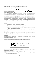
if not installed and used in accordance with the instructions, may cause harmful interference to radio communications. However, limits. VOIR LANOTICE D'INSTALLATIONAVANT DE RACCORDER AU RESEAU. Micro-Star International MS-7514 This device complies with Part 15 of the FCC Rules. Operation is subject - MSI P45 NEO3-FR | User Manual - Page 5
WEEE (Waste Electrical and Electronic Equipment) Statement v - MSI P45 NEO3-FR | User Manual - Page 6
vi - MSI P45 NEO3-FR | User Manual - Page 7
vii - MSI P45 NEO3-FR | User Manual - Page 8
1-1 Mainboard Specifications 1-2 Mainboard Layout 1-4 Packing Checklist 1-5 Chapter 2. Hardware Setup 2-1 Quick Components Guide 2-2 CPU (Central Processing Unit 2-3 Memory ...2-7 Power Supply ...2-9 Back Panel ...2-10 Connectors ...2-12 Jumper ...2-19 Slots ...2-20 Chapter 3 BIOS Setup - MSI P45 NEO3-FR | User Manual - Page 9
DOT (Dynamic OverClocking B-5 Clock ...B-6 Voltage ...B-7 FAN Speed ...B-8 Temperature ...B-9 User Profile ...B-10 Appendix C Intel ICH10R SATA RAID C-1 ICH10R Introduction C-2 BIOS Configuration C-3 Installing Driver C-10 Installing Software C-12 RAID Migration Instructions C-16 Recovery - MSI P45 NEO3-FR | User Manual - Page 10
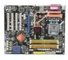
Neo3 Series (MS-7514 v1.X) ATX mainboard. The P45 Neo3/ G45 Neo3/ P43 Neo3 Series mainboards are based on Intel® P45/ G45/ P43 & ICH10/ ICH10R chipsets for optimal system efficiency. Designed to fit the advanced Core 2 Extreme, Core 2 Quad, Core 2 Duo, Pentium Dual-Core and Celeron Dual-Core LGA775 - MSI P45 NEO3-FR | User Manual - Page 11
MS-7514 Mainboard Mainboard Specifications Processor Support - Intel® Core 2 Extreme, Core 2 Quad, Core 2 Duo, Pentium Dual- Core and Celeron Dual-Core processors in the LGA775 package - Intel® next generation 45 nm Multi-core CPU *(For the latest information about CPU, please visit ht t p: / / gl - MSI P45 NEO3-FR | User Manual - Page 12
- 1 SPDIF-out pinheader - 1 CD-in connector - 1 front audio pinheader - 1 TPM Module connector (optional) - 2 Hardware Overclock FSB jumpers (JB1 & JB2) TPM (optional) - Supports TPM Slots - 1 PCI Express x16 slot, support up to PCI Express 2.0 x16 speed - 1 PCI Express x1 slot - 4 PCI slots - MSI P45 NEO3-FR | User Manual - Page 13
JB1 JB2 Intel ICH10/ ICH10R JCI1 JMicron JMB 363 SATA6 SATA4 SATA2 SATA8 JBAT1 JMicron JMB 381 (optional) BATT + SATA5 SATA3 SATA1 SATA7 J1394_1 (o pt ional ) J USB4 J USB3 JUSB2 JUSB1 J TPM1 (opt io nal) JFP2 JFP1 P45 Neo3/ G45 Neo3/ P43 Neo3 Series (MS-7514 v1.X) ATX Mainboard 1-4 - MSI P45 NEO3-FR | User Manual - Page 14
Packing Checklist Getting Started MSI motherboard MSI Driver/Utility CD Back IO Shield Power Cable SATA Cable IDE Cable User's Guide and Quick Guide * The pictures are for reference only and may vary from the packing contents of the product you purchased. 1-5 - MSI P45 NEO3-FR | User Manual - Page 15
Hardware Setup Chapter 2 Hardware Setup This chapter provides you with the information about hardware setup procedures. While doing the installation, be careful in holding the components and follow the installation procedures. For some components, if you install in the wrong orientation, the - MSI P45 NEO3-FR | User Manual - Page 16
MS-7514 Mainboard Quick Components Guide SYSFAN2, p.2-14 JPWR2, p.2-9 CPU, p.2-3 Back Panel, p.2-10 CPUFAN, p.2-14 DDR2 DIMMs, p.2-7 JPWR1, p.2-9 IDE1, p.2-12 PCIE, p.2-20 JB1/JB2, p.2-19 PCI, p.2-20 JAUD1, p.2-17 JCD1, p.2-16 JSP1, p.2-15 FDD1, p.2-12 - MSI P45 NEO3-FR | User Manual - Page 17
first to ensure the safety of CPU. Overclocking This mainboard is designed to support overclocking. However, please make sure your components are able to tolerate such abnormal setting, while doing overclocking. Any attempt to operate beyond product specifications is not recommended. We do not - MSI P45 NEO3-FR | User Manual - Page 18
MS-7514 Mainboard CPU & Cooler Installation W hen you are installing the CPU, make sure the CPU has a cooler attached on the top to prevent overheating. Meanwhile, do not forget to apply some thermal paste on CPU before installing the heat sink/cooler fan for better heat dispersion. Follow the - MSI P45 NEO3-FR | User Manual - Page 19
Lift the load lever up and open the load plate. Hardware Setup 6. After confirming the CPU direction for correct mating, put down the CPU in the socket housing frame. Be sure to grasp on the edge of the CPU base. Note that the alignment keys are matched. alignment key 7. Visually inspect if the - MSI P45 NEO3-FR | User Manual - Page 20
MS-7514 Mainboard 9. Press down the load lever lightly onto the load plate, and then secure the lever with the hook under retention tab. 10. Align the holes on the mainboard with the heatsink. Push down the cooler until its four clips get wedged into the holes of the mainboard. 11. Press the four - MSI P45 NEO3-FR | User Manual - Page 21
msi.com. tw/index.php?func=testreport DDR2 240-pin, 1.8V 56x2=112 pin 64x2=128 pin Dual-Channel Memory Population Rules In Dual-Channel mode, the memory DIMM slots. - To enable successful system boot-up, always insert the memory modules into the DIM M1 first. - Due to the chipset resource - MSI P45 NEO3-FR | User Manual - Page 22
MS-7514 Mainboard Installing Memory Modules 1. The memory module has only one notch on the center and will only fit in the right orientation. 2. Insert the memory module vertically into the DIMM slot. Then push it in until the golden finger on the memory module is deeply inserted in the DIMM slot. - MSI P45 NEO3-FR | User Manual - Page 23
24 GND ATX 4-pin Power Connector: JPWR2 This power connector is used to provide power to the CPU. 3 4 JPWR2 1 2 Pin Definition PIN SIGNAL 1 GND 2 GND 3 12V 4 12V ensure stable operation of the mainboard. 2. Power supply of 400 watts (and above) is highly recommended for system - MSI P45 NEO3-FR | User Manual - Page 24
MS-7514 Mainboard Back Panel Mouse Parallel Port (optional) 1394 Port LAN Line-In RS- is for a PS/2® mouse/keyboard. Parallel Port A parallel port is a standard printer port that supports Enhanced Parallel Port (EPP) and Extended Capabilities Parallel Port (ECP) mode. Serial Port The serial port - MSI P45 NEO3-FR | User Manual - Page 25
Hardware Setup LAN The standard RJ-45 LAN jack is for connection Yellow to the Local Area Network (LAN). You can connect a network cable to it. Green / Orange LED Color Left Yellow Green Right Orange LED State Condition Off LAN link is - MSI P45 NEO3-FR | User Manual - Page 26
MS-7514 Mainboard Connectors Floppy Disk Drive Connector: FDD1 This connector supports 360KB, 720KB, 1.2MB, 1.44MB or 2.88MB floppy disk drive. IDE Connector: IDE1 This connector supports IDE hard disk drives, to IDE device's documentation supplied by the vendors for jumper setting instructions. 2-12 - MSI P45 NEO3-FR | User Manual - Page 27
not fold the Serial ATA cable into 90-degree angle. Otherwise, data loss may occur during transmission. 2. SATA1~6 controlled by ICH10R/ ICH10, and the ICH10R supports RAID 0/ 1/ 0+1/ 5 mode. 3. SATA7~8 controlled by JMB 363 and they - MSI P45 NEO3-FR | User Manual - Page 28
MS-7514 Mainboard Fan Power Connectors: CPUFAN, SYSFAN1~2 The fan power connectors support to the recommended CPU fans at processor's official website or consult the vendors for proper CPU cooling fan. 2. CPUFAN supports fan control. You BIOS utility and clear the record. CINTRU 1 GND 2 JCI1 2-14 - MSI P45 NEO3-FR | User Manual - Page 29
Hardware Setup IEEE1394 Connector: J1394_1 (optional) This connector allows you to connect the IEEE1394 device via an optional IEEE1394 bracket. 2 10 1 9 J1394_1 Pin Definition PIN SIGNAL PIN 1 TPA+ 2 3 Ground 4 5 TPB+ 6 7 Cable power 8 9 Key (no pin) 10 SIGNAL TPAGround - MSI P45 NEO3-FR | User Manual - Page 30
MS-7514 Mainboard Front Panel Connectors: JFP1, JFP2 These connectors are for electrical connection to the front panel switches and LEDs. The JFP1 is compliant with Intel® Front Panel I/O Connectivity Design Guide. PIN Power Power LED Switch 1 +- 2 JFP1 2 1 10 3 9 4 +- -+ 5 HDD Reset - MSI P45 NEO3-FR | User Manual - Page 31
connect the front panel audio and is compliant with Intel® Front Panel I/O Connectivity Design Guide. JAUD1 9 1 10 2 HD Audio Pin Definition Module) module (optional). Please refer to the TPM security platform manual for more details and usages. 12 1314 Pin Signal Description 1 LCLK - MSI P45 NEO3-FR | User Manual - Page 32
MS-7514 Mainboard Front USB Connector: JUSB1~4 These connectors, compliant with Intel® I/O Connectivity Design Guide, is ideal for connecting high-speed USB interface peripherals such as USB HDD, digital cameras, MP3 players, printers, modems and the like. 10 9 2 1 JUSB1~4 Pin - MSI P45 NEO3-FR | User Manual - Page 33
clearing the CMOS while the system is on; it will damage the mainboard. Hardware Overclock FSB Jumpers: JB1, JB2 You can overclock the FSB to increase the processor frequency by changing the jumpers JB1 and JB2. Follow the instructions below to set the FSB. 1 3 JB1 JB2 Default 1 JB1 1 JB2 - MSI P45 NEO3-FR | User Manual - Page 34
MS-7514 Mainboard Slots PCI (Peripheral Component Interconnect) Express Slot The PCI Express slot supports the PCI Express interface expansion card. The PCI Express 2.0x 16 supports up to 8.0 GB/s transfer rate. The PCI Express x 1 supports up to 250 MB/s transfer rate. PCI Express x16 Slot PCI - MSI P45 NEO3-FR | User Manual - Page 35
Hardware Setup PCI Interrupt Request Routing The IRQ, acronym of interrupt request line and pronounced I-R-Q, are hardware lines over which devices can send interrupt signals to the microprocessor. The PCI IRQ pins are typically connected to the PCI bus pins as follows: PCI Slot 1 PCI Slot 2 PCI - MSI P45 NEO3-FR | User Manual - Page 36
This chapter provides information on the BIOS Setup program and allows you to configure the system for optimum use. You may need to run the Setup program when: ² An error message appears - MSI P45 NEO3-FR | User Manual - Page 37
MS-7514 Mainboard Entering Setup Power on the computer and the update for better system performance. Therefore, the description may be slightly different from the latest BIOS and should be held for reference only. 2. Upon boot-up, the 1st line appearing after the memory count is the BIOS version - MSI P45 NEO3-FR | User Manual - Page 38
BIOS Setup Control Keys Enter> Move to the sub-menu. If you want to return to the main menu, just press the . General Help The BIOS setup program provides a General Help screen. You can call up this screen from any menu by simply pressing . The - MSI P45 NEO3-FR | User Manual - Page 39
MS-7514 Mainboard The Main Menu Standard CMOS Features Use this menu for basic system configurations, such as time, date etc. Advanced BIOS BIOS Setting Password Use this menu to set the password for BIOS. Cell Menu Use this menu to specify your settings for frequency/voltage control and overclocking - MSI P45 NEO3-FR | User Manual - Page 40
this menu to load the default values set by the BIOS vendor for stable system performance. Load Optimized Defaults Use this menu to load the default values set by the mainboard manufacturer specifically for optimal performance of the mainboard. Save & Exit Setup Save changes to CMOS and exit setup - MSI P45 NEO3-FR | User Manual - Page 41
MS-7514 Mainboard Standard CMOS Features The items in Standard CMOS Features Menu includes some The format is . day Day of the week, from Sun to Sat, determined by BIOS. Read-only. month The month from Jan. to Dec. date The date from 1 to 31 can be keyed by numeric - MSI P45 NEO3-FR | User Manual - Page 42
BIOS Setup Device / Vendor / Size It will showing the device information that you connected to the SATA connector. LBA/Large M ode This allows you to enable or disable the LBA Mode. Setting to Auto enables LBA mode if the device supports IDE/ SATA connectors on the mainboard. Floppy Drive A This - MSI P45 NEO3-FR | User Manual - Page 43
MS-7514 Mainboard System Information Press to enter the sub-menu, and the following screen appears. This sub-menu shows the CPU information, BIOS version and memory status of your system (read only). 3-8 - MSI P45 NEO3-FR | User Manual - Page 44
Advanced BIOS Features BIOS Setup Full Screen Logo Display This item Version This field allows you to select which MPS (Multi-Processor Specification) version to be used for the operating system. You need to select the MPS version supported by your operating system. To find out which version - MSI P45 NEO3-FR | User Manual - Page 45
MS-7514 Mainboard Primary Graphic's Support Intel's Execute Disable Bit functionality can prevent certain classes of malicious "buffer overflow" attacks when combined with a supporting operating system. This functionality allows the processor to classify areas in memory by where application code - MSI P45 NEO3-FR | User Manual - Page 46
Device The items allow you to set the first/ second boot device where BIOS attempts to load the disk operating system. Boot From Other Device Setting Enter> to enter the sub-menu and the following screen appears: TCG/TPM SUPPORT Setting the option to [Yes] enables TPM (Trusted Platform Module) to - MSI P45 NEO3-FR | User Manual - Page 47
MS-7514 Mainboard Integrated Peripherals USB Controller This setting allows you to enable/disable the onboard USB controller. USB Device Legacy Support Select [Enabled] if you need to use a USB-interfaced device in the operating system. Onboard LAN Controller This item is used to enable/disable the - MSI P45 NEO3-FR | User Manual - Page 48
-Chip ATA Devices Press to enter the sub-menu and the following screen appears: PCI IDE BusMaster This item allows you to enable/ disable BIOS to used PCI busmastering for reading/ writing to IDE drives. On-Chip SATA Controller These items allow users to enable or disable the SATA controller - MSI P45 NEO3-FR | User Manual - Page 49
MS-7514 Mainboard AHCI Port 1~6 Select the type of device. Hard Disk S.M.A.R.T. This allows you to activate the S.M.A.R.T. (Self-Monitoring port will operate in ECP mode only. Choosing [ECP + EPP] will allow the onboard parallel port to support both the ECP and EPP modes simultaneously. 3-14 - MSI P45 NEO3-FR | User Manual - Page 50
section are available only when your BIOS supports S3 sleep mode. ACPI Function a low power state. In this state, no system context is lost (CPU or chipset) and hardware maintains all system context. [S3] The S3 is saved to main memory that remains powered while most other hardware components turn off - MSI P45 NEO3-FR | User Manual - Page 51
MS-7514 Mainboard Power Button Function This feature sets the function of the power button. Wake Up Event Setup Press and the following sub-menu appears. Wake Up Event By Setting to [BIOS] activates the following fields, and use the following fields to set the wake up events. Setting to [OS - MSI P45 NEO3-FR | User Manual - Page 52
BIOS Setup Resume By PCI-E Device W hen set to [Enabled], the feature allows your system to be awakened from the power saving modes through any event on PCIE device. Resume By RTC Alarm The field is used to enable or disable the feature of booting up the system on a scheduled time/date. 3-17 - MSI P45 NEO3-FR | User Manual - Page 53
MS-7514 Mainboard H/W Monitor Chassis Intrusion The field enables or disables the feature Enabled] later. CPU Smart FAN Target The mainboard provides the Smart Fan function which can control the CPU fan speed automatically depending on the current temperature to keep it with in a specific range. You - MSI P45 NEO3-FR | User Manual - Page 54
BIOS Setup BIOS Setting Password W hen you select this function, a message as below will appear on the screen: Type the password, up to six characters in length, and press . The password typed now will replace any previously set password from CMOS memory. You will be prompted to confirm the - MSI P45 NEO3-FR | User Manual - Page 55
MS-7514 Mainboard Cell Menu Important Change these settings only if you are familiar with the chipset. Current CPU / DRAM Frequency These items show the current clocks of CPU and Memory speed. Read-only. D.O.T. Control D.O.T. (Dynamic Overclocking Technology) is an automatic overclocking function, - MSI P45 NEO3-FR | User Manual - Page 56
BIOS Setup Important Even though the Dynamic Overclocking Technology is more stable than manual overclocking, basically, it is still risky. We suggest user to make sure that your CPU / memory modules can afford to overclocking regularly first. If you find the PC appears to be unstable or reboot - MSI P45 NEO3-FR | User Manual - Page 57
MS-7514 Mainboard DIMM1~4 Memory SPD Infromation Press to enter the sub-menu and the following screen appears. DIMM1~4 Memory SPD Infromation These items display the current status of the current DIMM Memory speed information such as memory type, max bandwidth, manufacture, part number, - MSI P45 NEO3-FR | User Manual - Page 58
BIOS Setup Important 1. If you do not have any EMI problem, leave the setting at [Disabled] for optimal system stability and local EMI regulation. 3. Remember to disable Spread Spectrum if you are overclocking because even a slight jitter can introduce a temporary boost in clock speed which may just - MSI P45 NEO3-FR | User Manual - Page 59
MS-7514 Mainboard USER SETTINGS Save Settings 1/ 2 These items are used to save the settings set by yourself to CMOS. Load Settings 1/ 2 These items are available after you save your settings in Save Settings 1/ 2 items , and are used to load the settings from CMOS. 3-24 - MSI P45 NEO3-FR | User Manual - Page 60
or Optimized values. The Optimized Defaults are the default values set by the mainboard manufacturer specifically for optimal performance of the mainboard. The Fail-Safe Defaults are the default values set by the BIOS vendor for stable system performance. W hen you select Load Fail-Safe Defaults - MSI P45 NEO3-FR | User Manual - Page 61
Appendix A Realtek ALC888 Audio The Realtek ALC888 provides 10-channel DAC that simultaneously supports 7.1 sound playback and 2 channels of independent stereo sound output (multiple streaming) through the Front-Out-Left and Front-OutRight channels. - MSI P45 NEO3-FR | User Manual - Page 62
MS-7514 Mainboard Installing the Realtek HD Audio Driver You need to install the HD audio driver for Realtek ALC888 codec to function properly before you can get access to 2-, 4-, 6-, 8- channel or 7.1+2 channel audio operations. Follow the procedures described below to install the drivers for - MSI P45 NEO3-FR | User Manual - Page 63
Realtek ALC888 Audio 3. Click Next to install the Realtek High Definition Audio Driver. 4. Click Finish to restart the system. Click here Select this option Click here A-3 - MSI P45 NEO3-FR | User Manual - Page 64
MS-7514 Mainboard Software Configuration After installing the audio driver, you are able to use the 2-, 4-, 6- or 8- channel audio feature now. Click the audio icon from the system tray at the lower-right corner of - MSI P45 NEO3-FR | User Manual - Page 65
Realtek ALC888 Audio Sound Effect Here you can select a sound effect you like from the Environment list. Environment Simulation You will be able to enjoy different sound experience by pulling down the arrow, several kinds of sound effect will be shown for selection. Realtek HD Audio Sound Manager - MSI P45 NEO3-FR | User Manual - Page 66
MS-7514 Mainboard Equalizer Selection Equalizer frees users from default settings; users may create their owned preferred settings by utilizing this tool. 10 bands of equalizer, ranging from - MSI P45 NEO3-FR | User Manual - Page 67
Realtek ALC888 Audio Frequently Used Equalizer Setting Realtek recognizes the needs that you might have. By leveraging our long experience at audio field, Realtek HD Audio Sound Manager provides you certain optimized equalizer settings that are frequently used for your quick enjoyment. [How to Use - MSI P45 NEO3-FR | User Manual - Page 68
MS-7514 Mainboard Mixer In the Mixer part, you may adjust the volumes of the rear and you plugging the speakers into the jacks on the front panel. 2. Multi-Stream Function ALC888 supports an outstanding feature called Multi-Stream, which means you may play different audio sources simultaneously and - MSI P45 NEO3-FR | User Manual - Page 69
Realtek ALC888 Audio W hen you are playing the first audio source (for example: use W indows Media Player to play DVD/VCD), the output will be played from the rear panel, which is the default setting. Then you must to select the Realtek HD Audio front output from the scroll list first, and use a - MSI P45 NEO3-FR | User Manual - Page 70
MS-7514 Mainboard 3. Playback control Tool Mute Playback device This function is to let you freely decide which ports to output the sound. And this is essential when - MSI P45 NEO3-FR | User Manual - Page 71
4. Recording control Realtek ALC888 Audio Tool Mute Recording device -Back Line in/Mic, Front Line in -Realtek HD Audio Input Mute You may choose to mute single or multiple volume controls or to completely mute sound input. Tool - Show the following volume controls This is to let you freely - MSI P45 NEO3-FR | User Manual - Page 72
MS-7514 Mainboard Audio I/O In this tab, you can easily configure your multi-channel audio function and speakers. You can choose a desired multi- changed to the one that is same as your device. - If not correct, Realtek HD Audio Manager will guide you to plug the device into the correct jack. A-12 - MSI P45 NEO3-FR | User Manual - Page 73
Connector Settings Click to access connector settings. Realtek ALC888 Audio Disable front panel jack detection (option) Find no function on front panel jacks? Please check if front jacks on your system are so-called AC'97 jacks. If so, please check this item to disable front panel jack detection - MSI P45 NEO3-FR | User Manual - Page 74
MS-7514 Mainboard S/PDIF Short for Sony/Philips Digital Interface, a standard audio file transfer format. S/PDIF allows the transfer of digital audio signals from one device to another - MSI P45 NEO3-FR | User Manual - Page 75
Realtek ALC888 Audio Test Speakers You can select the speaker by clicking it to test its functionality. The one you select will light up and make testing sound. If any speaker fails to make sound, then check whether the cable is inserted firmly to the connector or replace the bad speakers with - MSI P45 NEO3-FR | User Manual - Page 76
MS-7514 Mainboard Microphone In this tab you may set the function of the microphone. Select the Noise Suppression to remove the possible noise during recording, or select - MSI P45 NEO3-FR | User Manual - Page 77
Realtek ALC888 Audio 3D Audio Demo In this tab you may adjust your 3D positional audio before playing 3D audio applications like gaming. You may also select different environment to choose the most suitable environment you like. A-17 - MSI P45 NEO3-FR | User Manual - Page 78
MS-7514 Mainboard Information In this tab it provides some information about this HD Audio Configuration utility, including Audio Driver Version, DirectX Version, Audio Controller & Audio Codec. You may also select the language of this utility by choosing from the Language list. Also there is a - MSI P45 NEO3-FR | User Manual - Page 79
Realtek ALC888 Audio Hardware Setup Connecting the Speakers W hen you have set the Multi-Channel Audio Function mode properly in the software utility, connect your speakers to the correct phone jacks in accordance with the setting in software utility. n 2-Channel Mode for Stereo-Speaker Output 1 4 - MSI P45 NEO3-FR | User Manual - Page 80
MS-7514 Mainboard n 4-Channel Mode for 4-Speaker Output 1 4 2 5 3 6 1 Line In 2 Line Out (Front channels) 3 MIC 4 Line Out (Rear channels) 5 No function 6 No function A-20 - MSI P45 NEO3-FR | User Manual - Page 81
Realtek ALC888 Audio n 6-Channel Mode for 6-Speaker Output 1 4 2 5 3 6 1 Line In 2 Line Out (Front channels) 3 MIC 4 Line Out (Rear channels) 5 Line Out (Center and Subwoofer channel) 6 No function A-21 - MSI P45 NEO3-FR | User Manual - Page 82
MS-7514 Mainboard n 8-Channel Mode for 8-Speaker Output 1 4 2 5 3 6 1 Line In 2 Line Out (Front channels) 3 MIC 4 Line Out (Rear channel audio-out function on Vista operating system, you have to install the Realtek Audio Driver. Or, the mainboard will support 5.1 channel audio-out only. A-22 - MSI P45 NEO3-FR | User Manual - Page 83
monitor or configure the hardware status of MSI Mainboard & MSI Graphics card in windows, such as CPU/GPU clock, voltage, fan speed and the following requirements: 1. Intel Pentium4 / Celeron, AMD Athlon XP/ Sempron or compatible CPU with PCI Express slot. 2. 256MB system memory. 3. CD-ROM drive - MSI P45 NEO3-FR | User Manual - Page 84
MS-7514 Mainboard Activating Dual Core Center Once you have your Dual Core Center installed (locate the setup source file in the setup CD accompanying with your mainboard, path: Utility --> MSI Utility --> Dual Core Center), it will have an icon in the system tray, a short cut icon on the - MSI P45 NEO3-FR | User Manual - Page 85
V044 (V044 has to install with the version 8.26 or newer driver)/ V046 or V060 graphics card can activate the full function of this utility. If you install a graphics card of other brand, only hardware status of the MSI mainboard would be available. Introduction: Click each button appearing above - MSI P45 NEO3-FR | User Manual - Page 86
MS-7514 Mainboard AV/ Game/ Office/ Silence/ Cool MSI provides five common settings for different environments. The settings had been set to optimal values to reach better performance in each environment. Click the button - MSI P45 NEO3-FR | User Manual - Page 87
speed up the GPU, memory, fan and voltage automatically to make the system run smoother and faster. W hen the CPU/ GPU is temporarily Overclocking Technology is more stable than manual overclocking, basically, it is still risky. We suggest user to make sure that your CPU can afford to overclock - MSI P45 NEO3-FR | User Manual - Page 88
MS-7514 Mainboard Clock In the Clock sub-menu, you can see clock status (including FSB/ CPU clock of mainboard and GPU/ memory clock of graphics card) of your system. And you can select desired value for overclocking. There will be several items for you to select for overclocking after you - MSI P45 NEO3-FR | User Manual - Page 89
Voltage In the Voltage sub-menu, you can see voltage status (including Vcore, memory, GPU I voltage... etc.) of your system, and you can select desired value for overclocking. It will show several items to select for overclocking after you click the button. You can click the plus sign button to - MSI P45 NEO3-FR | User Manual - Page 90
MS-7514 Mainboard FAN Speed In the FAN Speed sub-menu, you can read fan with red color will be shown. Important 1. When you set the fan speed manually, please make sure to disabled the "CPU Smart FAN Target" item in the BIOS. 2. In the user profile, clicking the Save button can save the changes to - MSI P45 NEO3-FR | User Manual - Page 91
Dual Core Center Temperature In the Temperature sub-menu, you can see temperature status of your system. On the underside, it shows the graphs of the temperatures. Only the curves of the item which the button is lit up with red color will be shown. B-9 - MSI P45 NEO3-FR | User Manual - Page 92
MS-7514 Mainboard User Profile In the User Profile sub-menu, click the setting button that besides the user profile bar, and the next screen will appear. Here - MSI P45 NEO3-FR | User Manual - Page 93
Dual Core Center Use the draw bar to set the max system temperature. W hen the system temperature exceeds the threshold you defined, the system will pop up a warning message and shut down the system. Use the draw bar to set the minimal fan speed. When the fan speed is lower than the threshold you - MSI P45 NEO3-FR | User Manual - Page 94
Intel ICH10R SATA RAID Appendix C Intel ICH10R SATA RAID This appendix will assist users in configuring and enabling RAID functionality on platforms C-1 - MSI P45 NEO3-FR | User Manual - Page 95
MS-7514 Mainboard ICH10R Introduction The ICH10R provides a hybrid solution that combines 6 independent SATAII ports for support is created over these. Intel Matrix RAID Technology is the updating the data on the Master to the Recovery drive. They are Continuous Update Policy and On Request Update - MSI P45 NEO3-FR | User Manual - Page 96
should be integrated with the system BIOS on all motherboards with a supported Intel chipset. The Intel Matrix Stroage Manager Option ROM is the Intel RAID implementation and provides BIOS and DOS disk services. Please use + keys to enter the "Intel(R) RAID for Serial ATA" status screen - MSI P45 NEO3-FR | User Manual - Page 97
MS-7514 Mainboard After pressing the and keys simultaneously, the following window will appear: (1) Create RAID Volume 1. Select option 1 "Create RAID Volume" and press key. The - MSI P45 NEO3-FR | User Manual - Page 98
Intel ICH10R SATA RAID 3. In the Disk field, press key and the following screen appears. Use key to select the disks you want to - MSI P45 NEO3-FR | User Manual - Page 99
MS-7514 Mainboard Important Since you want to create two volumes (Intel Matrix RAID Technology), this default size (maximum) needs to be reduced. Type in a new size for the first volume. As an example: if you want - MSI P45 NEO3-FR | User Manual - Page 100
that all data on RAID drives will be lost. Important If your system currently boots to RAID and you delete the RAID volume in the Intel RAID Option ROM, your system will become unbootable. Select option 2 Delete RAID Volume from the main menu window and press key to select a RAID - MSI P45 NEO3-FR | User Manual - Page 101
MS-7514 Mainboard (3) Reset Disks to Non-RAID Select option 3 Reset Disks to Non-RAID and press to delete the RAID volume and remove any RAID structures - MSI P45 NEO3-FR | User Manual - Page 102
Intel ICH10R SATA RAID (4) Recovery Volume Options Select option 4 Recovery Volume Options and press to change recovery volume mode. The following screen appears: Recovery mode will change from Continuous Update to On-Request after you enable Only Recovery Disk or Only Master Disk. C-9 - MSI P45 NEO3-FR | User Manual - Page 103
MS-7514 Mainboard Installing Driver Install Driver in Windows Vista / XP / 2000 † New Windows Vista / XP / 2000 Installation The following details the installation of the drivers Please follow the instruction below to make an "Intel® RAID Driver" for yourself. 1. Insert the MSI CD into the CD - MSI P45 NEO3-FR | User Manual - Page 104
SATA RAID † Existing Windows Vista/XP/2000 Driver Installation 1. Insert the MSI CD into the CD-ROM drive. 2. The CD will auto-run and the setup screen will appear. 3. Under the Driver tab, click on Intel IAA RAID Edition. 4. The drivers will be automatically installed. † Confirming Windows Vista - MSI P45 NEO3-FR | User Manual - Page 105
MS-7514 Mainboard Installing Software Install Intel Matrix Storage Console The Intel Application Accelerator RAID Edition driver may be used to operate the hard drive from which the system is booting or a hard drive that contains important data. For this reason, you - MSI P45 NEO3-FR | User Manual - Page 106
Intel ICH10R SATA RAID The InstallShield Wizard will begin automatically for installation showed as following: Click on the Next button to proceed the installation in the welcoming window. C-13 - MSI P45 NEO3-FR | User Manual - Page 107
MS-7514 Mainboard The window shows the components to be installed. Click Next button to continue. After reading the license agreement in the following window, click Yes button to continue. C-14 - MSI P45 NEO3-FR | User Manual - Page 108
Intel ICH10R SATA RAID The following window appears to show the Readme File Information. It shows the system requirements and installation information. Once the installation is complete, the following window appears. C-15 - MSI P45 NEO3-FR | User Manual - Page 109
MS-7514 Mainboard RAID Migration Instructions The Intel Matrix Storage Console offers the BIOS. 2. Install the Intel Application Accelerator RAID Driver during W indows Setup. Refer to Installing Software for instructions on installing the driver during W indows Setup. 3. Install the Intel - MSI P45 NEO3-FR | User Manual - Page 110
Intel ICH10R SATA RAID Create RAID Volume from Existing Disk To create a RAID volume from an existing disk, choose Action --> Create RAID Volume from Existing Hard - MSI P45 NEO3-FR | User Manual - Page 111
MS-7514 Mainboard (1) Configure Volume Here you can configure the new RAID volume by entering the volume name, selecting the RAID level and strip size. † RAID Volume Name: A
-
 1
1 -
 2
2 -
 3
3 -
 4
4 -
 5
5 -
 6
6 -
 7
7 -
8
-
9
-
10
-
11
-
12
-
13
-
14
-
15
-
16
-
17
-
18
-
19
-
20
-
21
-
22
-
23
-
24
-
25
-
26
-
27
-
28
-
29
-
30
-
31
-
32
-
33
-
34
-
35
-
36
-
37
-
38
-
39
-
40
-
41
-
42
-
43
-
44
-
45
-
46
-
47
-
48
-
49
-
50
-
51
-
52
-
53
-
54
-
55
-
56
-
57
-
58
-
59
-
60
-
61
-
62
-
63
-
64
-
65
-
66
-
67
-
68
-
69
-
70
-
71
-
72
-
73
-
74
-
75
-
76
-
77
-
78
-
79
-
80
-
81
-
82
-
83
-
84
-
85
-
86
-
87
-
88
-
89
-
90
-
91
-
92
-
93
-
94
-
95
-
96
-
97
-
98
-
99
-
100
-
101
-
102
-
103
-
104
-
105
-
106
-
107
-
108
-
109
-
110
-
111
 |
 |
P45 Neo3/ G45 Neo3
P43 Neo3 Series
MS-7514 (v1.X) Mainboard
G52-75141X1