MSI P7NGM DIGITAL User Guide
MSI P7NGM DIGITAL - P7NGM-Digital Motherboard - Micro ATX Manual
 |
UPC - 816909049602
View all MSI P7NGM DIGITAL manuals
Add to My Manuals
Save this manual to your list of manuals |
MSI P7NGM DIGITAL manual content summary:
- MSI P7NGM DIGITAL | User Guide - Page 1
P7NGM-Digital Series MS-7530 (v1.X) Mainboard G52-75301X4 i - MSI P7NGM DIGITAL | User Guide - Page 2
's manual, please contact your place of purchase or local distributor. Alternatively, please try the following help resources for further guidance. Visit the MSI website for FAQ, technical guide, BIOS updates, driver updates, and other information: http://global.msi.com.tw/index.php? func=service - MSI P7NGM DIGITAL | User Guide - Page 3
1. Always read the safety instructions carefully. 2. Keep this User's Manual for future reference. 3. Keep this equipment k . 11. If any of the following situations arises, get the equipment checked by service personnel: † The power cord or plug is damaged. † Liquid has penetrated into the - MSI P7NGM DIGITAL | User Guide - Page 4
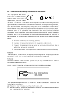
to comply with the limits for a Class B digital device, pursuant to Part 15 of the FCC and used in accordance with the instructions, may cause harmful interference to limits. VOIR LANOTICE D'INSTALLATIONAVANT DE RACCORDER AU RESEAU. Micro-Star International MS-7530 This device complies with Part - MSI P7NGM DIGITAL | User Guide - Page 5
WEEE (Waste Electrical and Electronic Equipment) Statement v - MSI P7NGM DIGITAL | User Guide - Page 6
vi - MSI P7NGM DIGITAL | User Guide - Page 7
vii - MSI P7NGM DIGITAL | User Guide - Page 8
Specifications 1-2 Mainboard Layout 1-4 Packing Checklist 1-5 Chapter 2. Hardware Setup 2-1 Quick Components Guide 2-2 CPU (Central Processing Unit 2-3 Memory ...2-7 Power Supply ...2-9 Back Panel ...2-11 Connectors ...2-13 Jumper ...2-20 Slots ...2-21 Chapter 3 BIOS Setup 3-1 Entering - MSI P7NGM DIGITAL | User Guide - Page 9
Appendix B NVIDIA RAID B-1 Introduction ...B-2 RAID Configuration B-3 Installing Driver ...B-7 NVIDIA RAID Utility Installation B-8 Using the NVMediaShield Software B-11 Appendix C Dual Core Center C-1 Activating Dual Core Center C-2 Main ...C-3 DOT (Dynamic OverClocking C-5 Clock ...C-6 - MSI P7NGM DIGITAL | User Guide - Page 10
Getting Started Chapter 1 Getting Started Thank you for choosing the P7NGM-Digital Series (MS7530 v1.X) Micro-ATX mainboard. The P7NGM-Digital Series mainboards are based on NVIDIA® nForce730i chipset for optimal system efficiency. Designed to fit the advanced Intel® Core 2 Extreme, Core 2 Quad, - MSI P7NGM DIGITAL | User Guide - Page 11
MS-7530 Mainboard Mainboard Specifications Processor Support - Intel® Core 2 Extrem e, Core 2 Quad, Core 2 Duo, Pentium dual- core and Celeron in the LGA775 package - Supports Intel® EIST Technology - Supports Intel® Hyper-Threading (HT) Technology (For the latest information about CPU, please visit - MSI P7NGM DIGITAL | User Guide - Page 12
Getting Started NVIDIA RAID - 6 SATA ports support RAID 0/ 1/ 0+1/ 5 or JBOD mode Floppy - 1 floppy port - Supports 1 FDD with 360KB, 720KB, 1.2MB, 1.44MB and 1 PCI Express x16 slot, supports PCIE 2.0 spec - 1 PCI Express x1 slot, supports PCIE 2.0 spec - 2 PCI slots, support 3.3V/ 5V PCI bus - MSI P7NGM DIGITAL | User Guide - Page 13
88 PCI 1 PCI 2 JCD1 JSP1 JAUD1 J1394_1 (op tional) JUSB1 JUSB2 SATA6 SATA4 SATA2 JMB368 SATA5 SATA3 SATA1 I/O Ch ip JUSB3 JCI1 JTPM1 JFP1 JFP2 P7NGM-Digital Series (MS-7530 v1.X) Micro-ATX Mainboard IDE 1 JLPT1 JCOM1 SYSFAN1 1-4 - MSI P7NGM DIGITAL | User Guide - Page 14
Packing Checklist Getting Started MSI motherboard MSI Driver/Utility CD Power Cable SATA Cable IDE Cable Back IO Shield User's Guide * The pictures are for reference only and may vary from the packing contents of the product you purchased. 1-5 - MSI P7NGM DIGITAL | User Guide - Page 15
Hardware Setup Chapter 2 Hardware Setup This chapter provides you with the information about hardware setup procedures. While doing the installation, be careful in holding the components and follow the installation procedures. For some components, if you install in the wrong orientation, the - MSI P7NGM DIGITAL | User Guide - Page 16
MS-7530 Mainboard Quick Components Guide JPWR2, p.2-9 CPU, p.2-3 Memroy DIMMs, p.2-7 CPUFAN1, p.2-15 Back Panel I/O, p.2-11 JPWR1, p.2-9 FDD1, p.2-13 JBAT1, p.2-20 PCI Express slots, p.2-21 PCI Slots, p.2-21 JAUD1, p.2-16 JCD1, p.2-16 JUSB1~3, p.2-17 - MSI P7NGM DIGITAL | User Guide - Page 17
about CPU, please visit http://global.msi.com.tw/index.php? func=cpuform2 Important Overheating Overheating will seriously damage the CPU and grounded outlet first to ensure the safety of CPU. Overclocking This mainboard is designed to support overclocking. However, please make sure your components - MSI P7NGM DIGITAL | User Guide - Page 18
MS-7530 Mainboard CPU & Cooler Installation W hen you are installing the CPU, make sure the CPU has a cooler attached on the top to prevent overheating. Meanwhile, do not forget to apply some thermal paste on CPU before installing the heat sink/cooler fan for better heat dispersion. Follow the - MSI P7NGM DIGITAL | User Guide - Page 19
Setup 5. Lift the load lever up and open the load plate. 6. After confirming the CPU direction for correct mating, put down the CPU in the socket housing frame. Be sure to grasp on the edge of the CPU base. Note that the alignment keys are matched. alignment key 7. Visually inspect if the - MSI P7NGM DIGITAL | User Guide - Page 20
MS-7530 Mainboard 9. Press down the load lever lightly onto the load plate, correctly inserted. locking switch Mainboard Hook Important 1. Read the CPU status in BIOS (Chapter 3). 2. Whenever CPU is not installed, always protect your CPU socket pin with the plastic cap covered (shown in Figure - MSI P7NGM DIGITAL | User Guide - Page 21
. For more information on compatible components, please visit http://global.msi.com. tw/index.php?func=testreport DDR2 240-pin, 1.8V 56x2=112 pin 64x2=128 pin Dual-Channel Memory Population Rules In Dual-Channel mode, the memory modules can transmit and receive data with two data bus lines - MSI P7NGM DIGITAL | User Guide - Page 22
MS-7530 Mainboard Installing Memory Modules 1. The memory module has only one notch on the center and will only fit in the right orientation. 2. Insert the memory module vertically into the DIMM slot. Then push it in until the golden finger on the memory module is deeply inserted in the DIMM slot. - MSI P7NGM DIGITAL | User Guide - Page 23
5V 11 +12V 23 +5V 12 +3.3V 24 GND ATX 4-Pin Power Connector: JPWR2 This power connector is used to provide power to the CPU. JPWR2 4 2 3 1 Pin Definition PIN SIGNAL 1 GND 2 GND 3 12V 4 12V pin 13 pin 12 Important 1. Make sure that all the connectors are connected to proper - MSI P7NGM DIGITAL | User Guide - Page 24
MS-7530 Mainboard Important Notification about Power Issue NForce chipset is very sensitive to ESD (Electrostatic Discharge), therefore this issue mostly happens while the users intensively swap memory modules under S5 (power-off) states, and the power code is plugged while installing modules. Due - MSI P7NGM DIGITAL | User Guide - Page 25
DIN connector is for a PS/2® mouse/keyboard. HDMI Port The High-Definition Multimedia Interface (HDMI) is an all-digital audio/video interface capable of transmitting uncompressed streams. HDMI supports all TV format, including standard, enhanced, or high-definition video, plus multi-channel - MSI P7NGM DIGITAL | User Guide - Page 26
MS-7530 Mainboard USB Port The USB (Universal Serial Bus) port is for attaching USB devices such as keyboard, mouse, or other USB-compatible devices. LAN The - MSI P7NGM DIGITAL | User Guide - Page 27
720KB, 1.2MB, 1.44MB or 2.88MB floppy disk drive. IDE Connector: IDE1 This connector supports IDE hard disk drives, optical disk drives and other IDE devices. Important If you install setting jumpers. Refer to IDE device's documentation supplied by the vendors for jumper setting instructions. 2-13 - MSI P7NGM DIGITAL | User Guide - Page 28
MS-7530 Mainboard Serial ATA Connector: SATA1~6 This connector is a high-speed Serial ATA interface port. Each connector can connect to one Serial ATA device. SATA6 SATA4 - MSI P7NGM DIGITAL | User Guide - Page 29
SENSOR +12V GND CPUFAN1 NC +12V GND SYSFAN1 Important 1. Please refer to the recommended CPU fans at processor's official website or consult the vendors for proper CPU cooling fan. 2. CPUFAN1 supports fan control. You can install Dual Core Center utility that will automatically control the - MSI P7NGM DIGITAL | User Guide - Page 30
MS-7530 Mainboard Front Panel Audio Connector: JAUD1 This connector allows you to connect the front panel audio and is compliant with Intel® Front Panel I/O Connectivity Design Guide the screen. To clear the warning, you must enter the BIOS utility and clear the record. 1 CINTRU GND JCI1 CD-In - MSI P7NGM DIGITAL | User Guide - Page 31
Hardware Setup Front USB Connector: JUSB1~3 This connector, compliant with Intel® I/O Connectivity Design Guide, is ideal for connecting high-speed USB interface peripherals such as USB HDD, digital cameras, MP3 players, printers, modems and the like. 2 10 1 9 JUSB1~3 Pin Definition PIN - MSI P7NGM DIGITAL | User Guide - Page 32
MS-7530 Mainboard IEEE1394 Connector: J1394_1 (optional) This connector allows you to connect the connects to a TPM (Trusted Platform Module) module (optional). Please refer to the TPM security platform manual for more details and usages. 2 14 1 13 JTPM 1 Pin Signal Description 1 LCLK LPC - MSI P7NGM DIGITAL | User Guide - Page 33
and LEDs. The JFP1 is compliant with Intel® Front Panel I/O Connectivity Design Guide. JFP1 Pin Definition Power Power LED Switch - + 2 10 1 9 port bracket. The parallel port is a standard printer port that supports Enhanced Parallel Port (EPP) and Extended Capabilities Parallel Port (ECP) - MSI P7NGM DIGITAL | User Guide - Page 34
MS-7530 Mainboard Jumper Clear CMOS Jumper: JBAT1 There is a CMOS RAM onboard that has a power supply from an external battery to keep the data of system - MSI P7NGM DIGITAL | User Guide - Page 35
2.0 spec and support the PCI Express interface expansion card. The PCI Express x16 slot supports up to 8.0 GB/s transfer rate. The PCI Express x1 slot supports up settings for the expansion card, such as jumpers, switches or BIOS configuration. PCI Interrupt Request Routing The IRQ, acronym of - MSI P7NGM DIGITAL | User Guide - Page 36
select 256 MB in VGA Share Memory field of Advanced BIOS Features in BIOS. Enabling Hybrid SLI Technology Power off the system and install the NVIDIA SLI graphic card that supports Hybrid SLI technology. After then, power on the system and install the driver of Hybrid SLI technology. Restart the - MSI P7NGM DIGITAL | User Guide - Page 37
This chapter provides information on the BIOS Setup program and allows you to configure the system for optimum use. You may need to run the Setup program when: ² An error message appears - MSI P7NGM DIGITAL | User Guide - Page 38
MS-7530 Mainboard Entering Setup Power memory count is the BIOS version. It is usually in the format: A7530NMS V1.1 100708 where: 1st digit refers to BIOS maker as A = AMI, W = AWARD, and P = PHOENIX. 2nd - 5th digit refers to the model number. 6th digit refers to the chipset as I = Intel, N = NVIDIA - MSI P7NGM DIGITAL | User Guide - Page 39
BIOS Setup Control Keys Enter> Move to the sub-menu. If you want to return to the main menu, just press the . General Help The BIOS setup program provides a General Help screen. You can call up this screen from any menu by simply pressing . The - MSI P7NGM DIGITAL | User Guide - Page 40
MS-7530 Mainboard The Main Menu Standard CMOS Features Use this menu for basic system configurations, such as time, date etc. Advanced BIOS BIOS Setting Password Use this menu to set the password for BIOS. Cell Menu Use this menu to specify your settings for frequency/voltage control and overclocking - MSI P7NGM DIGITAL | User Guide - Page 41
BIOS Setup Load Optimized Defaults Use this menu to load the default values set by the mainboard manufacturer specifically for optimal performance of the mainboard. Save & Exit Setup Save changes to CMOS and exit setup. Exit Without Saving Abandon all changes and exit setup. 3-5 - MSI P7NGM DIGITAL | User Guide - Page 42
MS-7530 Mainboard Standard CMOS Features The items in Standard CMOS Features Menu include The format is . day Day of the week, from Sun to Sat, determined by BIOS. Read-only. month The month from Jan. through Dec. date The date from 1 to 31 can be keyed by numeric - MSI P7NGM DIGITAL | User Guide - Page 43
BIOS Setup IDE Primary Master/ Slave, SATA 1/2/3/4/5/6 It will showing the device informations that you connected to the IDE/SATA connector. LBA/Large M ode This allows you to enable or disable the LBA Mode. Setting to Auto enables LBA mode if the device supports and set them to AHCI or IDE mode. 3-7 - MSI P7NGM DIGITAL | User Guide - Page 44
MS-7530 Mainboard Floppy Drive A This item allows you to set the type of floppy drives installed. Available options Press to enter the sub-menu, and the following screen appears. This sub-menu shows the CPU information, BIOS version and memory status of your system (read only). 3-8 - MSI P7NGM DIGITAL | User Guide - Page 45
Advanced BIOS Features BIOS Setup Full (Advanced Programmable Interrupt Controller). Due to compliance with PC2001 design guide, the system is able to run in APIC mode. Enabling . You need to select the MPS version supported by your operating system. To find out which version to use, consult - MSI P7NGM DIGITAL | User Guide - Page 46
MS-7530 Mainboard Primary Graphic's Adapter memory by where application code can execute and where it cannot. W hen a malicious worm attempts to insert code in the buffer, the processor disables code execution, preventing damage or worm propagation. C1E Support To enable this item to read the CPU - MSI P7NGM DIGITAL | User Guide - Page 47
BIOS Setup Hybrid SLI support This item is used to enable/ disable the Hybrid SLI. On-Chip VGA This setting allows you to enable or disable the on-chip VGA function. VGA Share Memory The system shares memory to the onboard VGA card. This setting controls the exact memory size shared to the VGA card. - MSI P7NGM DIGITAL | User Guide - Page 48
MS-7530 Mainboard Integrated Peripherals USB Controller This setting allows you to enable/disable the onboard USB controller. USB Device Legacy Support Select [Enabled] if you need to use a USB-interfaced device in the operating system. Onboard LAN Controller This item is used to enable/disable the - MSI P7NGM DIGITAL | User Guide - Page 49
screen appears: PCI IDE BusMaster This item allows you to enable/ disable BIOS to use PCI busmastering for reading/ writing to IDE drives. On- to enable or disable the SATA controller. RAID mode This item allows you to configure SATA mode. Setting options: [RAID],[AHCI] or [IDE]. I/O Devices Press < - MSI P7NGM DIGITAL | User Guide - Page 50
MS-7530 Mainboard Parallel Port M ode [Normal] Standard Parallel Port [EPP] Enhanced Parallel Port [ECP] Extended Capability Port [ECP& port will operate in ECP mode only. Choosing [ECP & EPP] will allow the onboard parallel port to support both the ECP and EPP modes simultaneously. 3-14 - MSI P7NGM DIGITAL | User Guide - Page 51
are available only when your BIOS supports S3 sleep mode. ACPI Function a low power state. In this state, no system context is lost (CPU or chipset) and hardware main- tains all system context. [S3] The files are saved to main memory that remains powered while most other hardware components turn - MSI P7NGM DIGITAL | User Guide - Page 52
MS-7530 Mainboard Power Button Function This feature sets the function of the power button Wake Up Event Setup Press and the following sub-menu appears. Wake Up Event By Setting to [BIOS] activates the following fields, and use the following fields to set the wake up events. Setting to [OS - MSI P7NGM DIGITAL | User Guide - Page 53
H/W Monitor BIOS Setup Chassis Intrusion The field enables or disables the feature of recording it with in a specific range. You can select a fan temperature target value. If the current CPU fan temperature reaches to the target value, the smart fan function will be activated. It provides several - MSI P7NGM DIGITAL | User Guide - Page 54
MS-7530 Mainboard BIOS Setting Password W hen you select this function, a message as below will appear on the screen: Type the password, up to six characters in length, and press . The password typed now will replace any previously set password from CMOS memory. You will be prompted to - MSI P7NGM DIGITAL | User Guide - Page 55
clocks of CPU and Memory speed. Read-only. Intel EIST The Enhanced Intel SpeedStep technology allows you to set the performance level of the microprocessor whether the computer is running on battery or AC power. This field will appear after you installed the CPU which support speedstep technology - MSI P7NGM DIGITAL | User Guide - Page 56
MS-7530 Mainboard Adjusted CPU Frequency (M Hz) It shows the adjusted CPU Manual], some fields will appear and selectable. CAS Latency(CL) W hen the DRAM Timing M ode sets to [Manual Mode sets to [Manual], the field Mode sets to [Manual], this field is Manual], this field is adjustable. This setting determines - MSI P7NGM DIGITAL | User Guide - Page 57
BIOS Setup tRC W hen the DRAM Timing M ode sets to [Manual], the field is adjustable. The rowcycle time determines the minimum number of clock cycles a memory row takesto complete a full cycle, from minimize the electromagnetic interference (EMI). CPU Voltage (V) This item allows you to increase the - MSI P7NGM DIGITAL | User Guide - Page 58
MS-7530 Mainboard DRAM Voltage (V) Adjusting the memory voltage can increase the memory speed. NB Voltage (V) Adjust the North Bridge chipset voltage. VTT FSB Voltage (V) This item allows you to set the FSB VTT voltage. CPU/LDT Spread Spectrum This setting is used to enable or disable the CPU Spread - MSI P7NGM DIGITAL | User Guide - Page 59
BIOS Setup CPU and Memory Clock Overclocking The FSB Clock/ Memory Clock & FSB/DRAM ratio are the items for you to overclock the CPU and the Memory. Please refer to the descriptions of these fields for more information. Important This motherboard supports overclocking greatly. However, please make - MSI P7NGM DIGITAL | User Guide - Page 60
MS-7530 Mainboard Load Fail-Safe/ Optimized Defaults The two options on the main menu allow users to restore all of the BIOS settings to the default Fail-Safe or Optimized values. The Optimized Defaults are the default values set by the mainboard manufacturer specifically for optimal performance - MSI P7NGM DIGITAL | User Guide - Page 61
Realtek ALC888 Audio Appendix A Realtek ALC888 Audio The Realtek ALC888 provides 10-channel DAC that simultaneously supports 7.1 sound playback and 2 channels of independent stereo sound output (multiple streaming) through the Front-Out-Left and Front-OutRight channels. A-1 - MSI P7NGM DIGITAL | User Guide - Page 62
MS-7530 Mainboard Installing the Realtek HD Audio Driver You need to install the HD audio driver for Realtek ALC888 codec to function properly before you can get access to 2-, 4-, 6-, 8- channel or 7.1+2 channel audio operations. Follow the procedures described below to install the drivers for - MSI P7NGM DIGITAL | User Guide - Page 63
Realtek ALC888 Audio 3. Click Next to install the Realtek High Definition Audio Driver. 4. Click Finish to restart the system. Click here Select this option Click here A-3 - MSI P7NGM DIGITAL | User Guide - Page 64
MS-7530 Mainboard Software Configuration After installing the audio driver, you are able to use the 2-, 4-, 6- or 8- channel audio feature now. Click the audio icon from the system tray at the lower-right corner of - MSI P7NGM DIGITAL | User Guide - Page 65
Realtek ALC888 Audio Sound Effect Here you can select a sound effect you like from the Environment list. Environment Simulation You will be able to enjoy different sound experience by pulling down the arrow, several kinds of sound effect will be shown for selection. Realtek HD Audio Sound Manager - MSI P7NGM DIGITAL | User Guide - Page 66
MS-7530 Mainboard Equalizer Selection Equalizer frees users from default settings; users may create their owned preferred settings by utilizing this tool. 10 bands of equalizer, ranging - MSI P7NGM DIGITAL | User Guide - Page 67
Realtek ALC888 Audio Frequently Used Equalizer Setting Realtek recognizes the needs that you might have. By leveraging our long experience at audio field, Realtek HD Audio Sound Manager provides you certain optimized equalizer settings that are frequently used for your quick enjoyment. [How to Use - MSI P7NGM DIGITAL | User Guide - Page 68
MS-7530 Mainboard Mixer In the Mixer part, you may adjust the volumes of the rear you plugging the speakers into the jacks on the front panel. 2. Multi-Stream Function ALC888 supports an outstanding feature called Multi-Stream, which means you may play different audio sources simultaneously and - MSI P7NGM DIGITAL | User Guide - Page 69
Realtek ALC888 Audio W hen you are playing the first audio source (for example: use W indows Media Player to play DVD/VCD), the output will be played from the rear panel, which is the default setting. Then you must to select the Realtek HD Audio front output from the scroll list first, and use a - MSI P7NGM DIGITAL | User Guide - Page 70
MS-7530 Mainboard 3. Playback control Tool Mute Playback device This function is to let you freely decide which ports to output the sound. And this is essential - MSI P7NGM DIGITAL | User Guide - Page 71
4. Recording control Realtek ALC888 Audio Tool Mute Recording device -Back Line in/Mic, Front Line in -Realtek HD Audio Input Mute You may choose to mute single or multiple volume controls or to completely mute sound input. Tool - Show the following volume controls This is to let you freely - MSI P7NGM DIGITAL | User Guide - Page 72
MS-7530 Mainboard Audio I/O In this tab, you can easily configure your multi-channel audio function and speakers. You can choose a desired jack changed to the one that is same as your device. - If not correct, Realtek HD Audio Manager will guide you to plug the device into the correct jack. A-12 - MSI P7NGM DIGITAL | User Guide - Page 73
Connector Settings Click to access connector settings. Realtek ALC888 Audio Disable front panel jack detection (option) Find no function on front panel jacks? Please check if front jacks on your system are so-called AC'97 jacks. If so, please check this item to disable front panel jack detection - MSI P7NGM DIGITAL | User Guide - Page 74
MS-7530 Mainboard S/PDIF Short for Sony/Philips Digital Interface, a standard audio file transfer format. S/PDIF allows the transfer of digital audio signals from one device to another without having to be converted first to an analog format. Maintaining the viability of a digital signal prevents - MSI P7NGM DIGITAL | User Guide - Page 75
Realtek ALC888 Audio Test Speakers You can select the speaker by clicking it to test its functionality. The one you select will light up and make testing sound. If any speaker fails to make sound, then check whether the cable is inserted firmly to the connector or replace the bad speakers with - MSI P7NGM DIGITAL | User Guide - Page 76
MS-7530 Mainboard Microphone In this tab you may set the function of the microphone. Select the Noise Suppression to remove the possible noise during recording, or - MSI P7NGM DIGITAL | User Guide - Page 77
Realtek ALC888 Audio 3D Audio Demo In this tab you may adjust your 3D positional audio before playing 3D audio applications like gaming. You may also select different environment to choose the most suitable environment you like. A-17 - MSI P7NGM DIGITAL | User Guide - Page 78
MS-7530 Mainboard Information In this tab it provides some information about this HD Audio Configuration utility, including Audio Driver Version, DirectX Version, Audio Controller & Audio Codec. You may also select the language of this utility by choosing from the Language list. Also there is a - MSI P7NGM DIGITAL | User Guide - Page 79
Realtek ALC888 Audio Hardware Setup Connecting the Speakers W hen you have set the Multi-Channel Audio Function mode properly in the software utility, connect your speakers to the correct phone jacks in accordance with the setting in software utility. n 2-Channel Mode for Stereo-Speaker Output 1 4 - MSI P7NGM DIGITAL | User Guide - Page 80
MS-7530 Mainboard n 4-Channel Mode for 4-Speaker Output 1 4 2 5 3 6 1 Line In 2 Line Out (Front channels) 3 MIC 4 Line Out (Rear channels) 5 No function 6 No function A-20 - MSI P7NGM DIGITAL | User Guide - Page 81
Realtek ALC888 Audio n 6-Channel Mode for 6-Speaker Output 1 4 2 5 3 6 1 Line In 2 Line Out (Front channels) 3 MIC 4 Line Out (Rear channels) 5 Line Out (Center and Subwoofer channel) 6 No function A-21 - MSI P7NGM DIGITAL | User Guide - Page 82
MS-7530 Mainboard n 8-Channel Mode for 8-Speaker Output 1 4 2 5 3 6 1 Line In 2 Line Out (Front channels) 3 MIC 4 Line Out (Rear channel audio-out function on Vista operating system, you have to install the Realtek Audio Driver. Or, the mainboard will support 5.1 channel audio-out only. A-22 - MSI P7NGM DIGITAL | User Guide - Page 83
B NVIDIA RAID NVIDIA RAID NVIDIA brings Redundant Array of Independent Disks (RAID) technology-which is used by the world's leading businesses-to the common PC desktop. This tech- nology uses multiple drives to either increase total disk space or to offer data protection. For all levels, RAID - MSI P7NGM DIGITAL | User Guide - Page 84
MS-7530 Mainboard Introduction System Requirement Operating System Support NVRAID supports the following operating systems: W indows XP, W indows Vista RAID Arrays NVRAID supports the following types of RAID arrays described in this section: RAID 0: RAID 0 defines a disk striping scheme that - MSI P7NGM DIGITAL | User Guide - Page 85
NVIDIA RAID RAID Configuration Basic Configuration Instructions The following are the basic steps for configuring NVRAID: Non-Bootable RAID Array 1. Choose the hard disks that are to be RAID enabled in the system BIOS. (Refer the bios section for details.) 2. Specify the RAID level, either Mirroring - MSI P7NGM DIGITAL | User Guide - Page 86
MS-7530 Mainboard Understanding the "Define a New Array" Window Use the Define a New Array window to • Select the RAID Mode • Set up the Striping Block • Specify which disks to use for the RAID Array The SATA ports are called channels and they are associated with adapters. The first digit in the - MSI P7NGM DIGITAL | User Guide - Page 87
NVIDIA RAID Using the Define a New Array Window If necessary, press the tab key to move from field to field until the appropriate field is highlighted. • Selecting the RAID Mode By default, this is set to [Mirroring]. To change to a different RAID RAID Config BIOS setup page appear in the Free Disks - MSI P7NGM DIGITAL | User Guide - Page 88
MS-7530 Mainboard Completing the RAID BIOS Setup 1. After assigning your RAID array disks, press F7. The Clear disk data prompt appears. 2. Press Y if you want to wipe out all the data from the RAID array, otherwise press N. You must choose Yes if the drives were previously used as RAID drives. The - MSI P7NGM DIGITAL | User Guide - Page 89
A: drive,and then press ENTER. 4. You should be shown a list of available NVRAID Adapaters. Important Please follow the instruction below to make an "NVIDIA RAID Driver" for yourself. 1. Insert the MSI CD into the CD-ROM drive. 2. Click the "Browse CD" on the Setup screen. 3. Copy all the contents - MSI P7NGM DIGITAL | User Guide - Page 90
MS-7530 Mainboard NVIDIA RAID Utility Installation Installing the NVIDIA MediaShield Software Under Windows (for Non-bootable RAID Array) The existing W indows Serial ATA driver must be upgraded to use the NVIDIA Serial ATA driver. This section describes how to run the setup application and install - MSI P7NGM DIGITAL | User Guide - Page 91
NVIDIA RAID Initializing and Using the Disk Array The RAID array is now ready to be initialized under W indows. 1. Launch Computer Management by clicking "Start" --> "Settings" --> "Control Panel" then open the "Administrative Tools" folder and - MSI P7NGM DIGITAL | User Guide - Page 92
MS-7530 Mainboard 5. Check the disk in the list if you want to make the array a dynamic disk, then click Next. The Completing the Initialize and Convert - MSI P7NGM DIGITAL | User Guide - Page 93
NVIDIA RAID Using the NVMediaShield Software Accessing the Storage Page To access the NVIDIA Control Panel Storage page: 1. Click Star-> Programs-> NVIDIA Corporation-> NVIDIA Control Panel-> Storage. 2. The NVIDIA Control Panel - Storage page appears. B-11 - MSI P7NGM DIGITAL | User Guide - Page 94
MS-7530 Mainboard Using the Storage Page From the Storage page, you can accomplish the only to fault-tolerant arrays such as RAID 1, RAID 0+1, or RAID 5 Arrays. Instructions Click Rebuild array to start the Rebuild Create Array W izard and then follow the instructions. You can press F1 to access - MSI P7NGM DIGITAL | User Guide - Page 95
NVIDIA RAID Designate a Spare Disk About Spare Disks You can designate a hard drive to be used as a spare drive for a RAID 1, RAID 0+1 or RAID 5 array. The spare drive can take over for a failed disk. MediaShield RAID supports two types of spare drives: Free Disk A free disk is a disk that is not - MSI P7NGM DIGITAL | User Guide - Page 96
MS-7530 Mainboard Remove a Spare The Remove spare option appears only if you have a RAID array with a spare disk allocated to it. Click Remove spare to start the Remove Spare W izard and then follow the instructions. You can press F1 to access the online help that walks you through the W izard with - MSI P7NGM DIGITAL | User Guide - Page 97
NVIDIA RAID Specific Migrating Requirements The following table lists the disk requirements for a new RAID array for various migrating combinations. From RAID 0 RAID 1 RAID 0+1 RAID 5 To RAID 0 RAID 1 RAID 0+1 RAID5 RAID 0 RAID 1 RAID 0+1 RAID 5 RAID 0 RAID 1 RAID 0+1 RAID 5 RAID 0 RAID 1 RAID - MSI P7NGM DIGITAL | User Guide - Page 98
MS-7530 Mainboard View Storage Information • You can use the Storage page to view the following storage information about the hard drives in your system: - W hich RAID arrays are set up - The process state of each array - W hich drives are configured for each RAID side menu. Instructions Click View - MSI P7NGM DIGITAL | User Guide - Page 99
monitor or configure the hardware status of MSI Mainboard & MSI Graphics card in windows, such as CPU/GPU clock, voltage, fan speed and Pentium4 / Celeron, AMD Athlon XP/ Sempron or compatible CPU with PCI Express slot. 2. 256MB system memory. 3. CD-ROM drive for software installation. 4. Operation - MSI P7NGM DIGITAL | User Guide - Page 100
MS-7530 Mainboard Activating Dual Core Center Once you have your Dual Core Center installed (locate the setup source file in the setup CD accompanying with your mainboard, path: Utility --> MSI --> Dual Core Center), it will have an icon in the system tray, a short cut icon on the desktop, and a - MSI P7NGM DIGITAL | User Guide - Page 101
. MB Click MB button to read current CPU temperature, FSB and CPU clock of mainboard will show below. VGA Click VGA button to read current GPU temperature, GPU clock and memory clock of graphics card will show below. DOT Click DOT button to enable or disable the Dynamic Overclocking Technology. C-3 - MSI P7NGM DIGITAL | User Guide - Page 102
MS-7530 Mainboard AV/ Game/ Office/ Silence/ Cool MSI provides five common settings for different environments. The settings had been set to optimal values to reach better performance in each environment. Click the button - MSI P7NGM DIGITAL | User Guide - Page 103
-UP Rate button DOT FSB-DOWN Rate button Important Even though the Dynamic Overclocking Technology is more stable than manual overclocking, basically, it is still risky. We suggest user to make sure that your CPU can afford to overclock regularly first. If you find the PC appears to be unstable or - MSI P7NGM DIGITAL | User Guide - Page 104
MS-7530 Mainboard Clock In the Clock sub-menu, you can see clock status (including FSB/ CPU clock of mainboard and GPU/ memory clock of graphics card) of your system. And you can select desired value for overclocking. There will be several items for you to select for overclocking after you - MSI P7NGM DIGITAL | User Guide - Page 105
Voltage In the Voltage sub-menu, you can see voltage status (including Vcore, memory, GPU I voltage... etc.) of your system, and you can select desired value for overclocking. It will show several items to select for overclocking after you click the button. You can click the plus sign button to - MSI P7NGM DIGITAL | User Guide - Page 106
MS-7530 Mainboard FAN Speed In the FAN Speed sub-menu, you can read fan with red color will be shown. Important 1. When you set the fan speed manually, please make sure to disable the "CPU Smart FAN Target" item in the BIOS. 2. In the user profile, clicking the Save button can save the changes to - MSI P7NGM DIGITAL | User Guide - Page 107
Dual Core Center Temperature In the Temperature sub-menu, you can see temperature status of your system. On the underside, it shows the graphs of the temperatures. Only the curves of the item which the button is lit up with red color will be shown. C-9 - MSI P7NGM DIGITAL | User Guide - Page 108
MS-7530 Mainboard User Profile In the User Profile sub-menu, click the setting button that besides the user profile bar, and the next screen will appear. - MSI P7NGM DIGITAL | User Guide - Page 109
Dual Core Center Use the draw bar to set the max system temperature. W hen the system temperature exceeds the threshold you defined, the system will pop up a warning message and shut down the system. Use the draw bar to set the minimal fan speed. When the fan speed is lower than the threshold you
-
 1
1 -
 2
2 -
 3
3 -
 4
4 -
 5
5 -
 6
6 -
 7
7 -
8
-
9
-
10
-
11
-
12
-
13
-
14
-
15
-
16
-
17
-
18
-
19
-
20
-
21
-
22
-
23
-
24
-
25
-
26
-
27
-
28
-
29
-
30
-
31
-
32
-
33
-
34
-
35
-
36
-
37
-
38
-
39
-
40
-
41
-
42
-
43
-
44
-
45
-
46
-
47
-
48
-
49
-
50
-
51
-
52
-
53
-
54
-
55
-
56
-
57
-
58
-
59
-
60
-
61
-
62
-
63
-
64
-
65
-
66
-
67
-
68
-
69
-
70
-
71
-
72
-
73
-
74
-
75
-
76
-
77
-
78
-
79
-
80
-
81
-
82
-
83
-
84
-
85
-
86
-
87
-
88
-
89
-
90
-
91
-
92
-
93
-
94
-
95
-
96
-
97
-
98
-
99
-
100
-
101
-
102
-
103
-
104
-
105
-
106
-
107
-
108
-
109
 |
 |
P7NGM-Digital Series
MS-7530 (v1.X) Mainboard
G52-75301X4