MSI PM8M-V User Guide
MSI PM8M-V - Motherboard - Micro ATX Manual
 |
View all MSI PM8M-V manuals
Add to My Manuals
Save this manual to your list of manuals |
MSI PM8M-V manual content summary:
- MSI PM8M-V | User Guide - Page 1
if not installed and used in accordance with the instruction manual, may cause harmful interference to radio communications. Operation VOIR LA NOTICE D'NSTALLATION AVANT DE RACCORDER AU RESEAU. Micro-Star International MS-7104 This device complies with Part 15 of the FCC Rules. Operation is - MSI PM8M-V | User Guide - Page 2
Megatrends Inc. Kensington and MicroSaver are registered trademarks of the Kensington Technology Group. PCMCIA and CardBus are registered trademarks of the Personal Computer Memory Card International Association. Revision History Revision Revision History V1.0 First release of V-Series with VIA - MSI PM8M-V | User Guide - Page 3
safety instructions carefully. 2. Keep this User Manual for Always Unplug the Power Cord before inserting any add-on card or module. 9. All cautions and warnings on the equipment the following situations arises, get the equipment checked by a service personnel: - The power cord or plug is damaged. - MSI PM8M-V | User Guide - Page 4
Table of Contents English 1 Français 17 Deutsch 31 47 61 75 iv - MSI PM8M-V | User Guide - Page 5
Specifications CPU l Supports Intel Pentium 4 /Prescott (Socket 478) processor l Supports up to 3.4GHz, FSB@800/533MHz (For the latest information about CPU, please visit our Web site at http://www.msi.com.tw/program/products/mainboard/mbd/pro_mbd_cpu_support.php ) Chipset l VIA P4M800 chipset (645 - MSI PM8M-V | User Guide - Page 6
- 2 SATA 150 - 1 VGA port Audio l AC97 link controller integrated in VT8237R l Realtek ALC655 6-Channel software audio codec - Compliant with AC97 v2.2 spec. LAN l Realtek 8201CL - Integrated Fast Ethernet PHY - Supports 10Mb/s, 100Mb/s - Compliant with PCI 2.2 - Supports ACPI Power Management BIOS - MSI PM8M-V | User Guide - Page 7
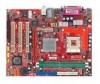
: USB Ports JPW1 ATX1 T: Line-In J3 M: Line-Out B: Mic JCASE1 JCOM 1 Winbond W83627THF BIOS Codec JSP1 VIA P4M800 AGP Slot PCI Slot 1 PCI Slot 2 PCI Slot 3 VIA VT8237R JAUDIO1CD_IN1 FDD 1 JUSB1 JUSB2 JFP2 J4 MS-7104v1.X Micro-ATX Mainboard IDE 1 BATT + SATA2 SATA1 JBAT1 JFP1 3 - MSI PM8M-V | User Guide - Page 8
memory modules, and expansion cards, as well as how to setup the jumpers on the mainboard. It also provides the instructions on connecting the peripheral information about CPU, please visit our Web site at http://www.msi.com.tw/program/products/mainboard/mbd/pro_mbd_cpu_support.php Example of CPU - MSI PM8M-V | User Guide - Page 9
MSI ensure the safety of CPU. CPU Installation Procedures for Socket 478 1. Please turn off the power and unplug the power cord before installing the CPU. Follow the instructions below to install the Heatsink/Fan: 1. Locate the CPU and its retention mechanism on the motherboard. 2. Position the heatsink - MSI PM8M-V | User Guide - Page 10
in PC Health Status of H/W Monitor in BIOS for the CPU temperature. 3. Do not touch the CPU socket pins to avoid damage. Memory The mainboard provides supports up to a maximum size of 1GB. You can install either single- or double-sided modules to meet your own needs. Please refer to http://www.msi - MSI PM8M-V | User Guide - Page 11
133 MHz 166 MHz 200MHz YES YES YES YES YES YES For the updated supporting memory modules, please visit our Web site at http://www.msi.com.tw/program/products/mainboard/mbd/pro_mbd_trp_list.php Power Supply The mainboard supports ATX power supply for the power system. Before inserting the power - MSI PM8M-V | User Guide - Page 12
Master and a Slave drive. MSI Reminds You... If you install for jumper setting instructions. Chassis Intrusion Switch BIOS setting and clear the status. Fan Power Connectors: CPU_FAN/SYS_FAN The CPU_FAN (processor fan) and SYS_FAN (system fan) support system cooling fan with +12V. They support - MSI PM8M-V | User Guide - Page 13
interface ports. The ports support 1st generation Serial ATA data with Intel Front Panel I/O Connectivity Design Guide. Power Power LED Switch 2 10 1 Format) interface for digital audio transmission. Front USB MP3 players, printers, modems and the like. MSI Reminds You... Note that the pins of - MSI PM8M-V | User Guide - Page 14
front panel audio and is compliant with Intel ® Front Panel I/O Connectivity Design Guide. MSI Reminds You... If you do not want to connect to the front audio header, pins to directly access main memory. The slot supports 8x/4x AGP card. PCI (Peripheral Component Interconnect) Slots The PCI - MSI PM8M-V | User Guide - Page 15
any necessary hardware or software settings for the expansion card, such as jumpers, switches or BIOS configuration. PCI Interrupt Request Routing The IRQ, acronym of interrupt request line and pronounced I-R-Q, are hardware lines over which devices can send interrupt signals to - MSI PM8M-V | User Guide - Page 16
Use this menu for basic system configurations, such as time, date etc. Advanced BIOS Features Use this menu to setup the items of special enhanced features. Advanced /PCI Configurations This entry appears if your system supports PnP/PCI. H/W Monitor This entry shows information of your CPU - MSI PM8M-V | User Guide - Page 17
for CPU/AGP frequency/voltage control and overclocking. Load Optimized Defaults Use this menu to load the BIOS values for the best system performance, but the system stability may be affected. BIOS Setting Password Use this menu to set User Password. Save & Exit Setup Save changes to CMOS and - MSI PM8M-V | User Guide - Page 18
AGP, DRAM and overclocking functions. MSI Reminds You... Change these settings only the processor relative to the external or motherboard clock speed. Adjust CPU/AGP/PCI Frequency allowing you to increase the performance of your AGP display card when overclocking, but the stability may be affected. - MSI PM8M-V | User Guide - Page 19
Spread Spectrum When the motherboard's clock generator pulses, the extreme values of the pulses are reduced to flatter curves. If you do not have any EMI problem, leave the setting at Disabled for optimal system stability and performance. But if you cause your overclocked processor to lock up. 15 - MSI PM8M-V | User Guide - Page 20
Load Optimized Defaults You can load the optimized values provided by the mainboard manufacturer for the stable performance. 16 - MSI PM8M-V | User Guide - Page 21
processeurs Intel Pentium 4 Prescott (Socket 478) l Supporte jusqu'à 3.4GHz, FSB@800/533MHz (Pour les dernières mises à jours concernant les CPU, vous pouvez visiter : http://www.msi.com.tw/program/products/mainboard/mbd/pro_mbd_cpu_support.php.) Chipset l Chipset VIA P4M800 (645 BGA) - Processeur - MSI PM8M-V | User Guide - Page 22
B - 2 SATA 150 - 1 VGA port Audio l Contrôleur AC97 link intégré dans VT8237R l 6 canaux audio codec Realtek ALC655 - Compatible avec les spec AC97 v2.2. LAN l Realtek 8201CL - Fast Ethernet PHY Intégré - Supporte 10MB/s, 100MB/s - Compatible avec PCI 2.2 l Supporte l'ACPI Power Management BIOS l La - MSI PM8M-V | User Guide - Page 23
Bottom: Keyboard S Y S _ FA N Top: Parallel Port Bottom: COM A VGA Port CPU_FAN IDE 2 USB Ports Top: LAN Jack Bottom: USB Ports JPW1 ATX1 T: Line-In J3 M: Line-Out B: Mic JCASE1 JCOM 1 Winbond W83627THF BIOS Codec JSP1 VIA P4M800 AGP Slot PCI Slot 1 PCI Slot 2 PCI Slot 3 VIA - MSI PM8M-V | User Guide - Page 24
instructions de montage pour éviter d'endommager quoi que ce soit. Central Processing Unit: CPU La carte supporte les processeurs Intel Pentium 4 Prescott. Elle utilise le socket x Multiplicateur = 133MHz x 23 = 3.06 GHz MSI Vous Rappelle... Surchauffe Une surchauffe endommagera sérieusement le CPU - MSI PM8M-V | User Guide - Page 25
socket 478 1. Veuillez éteindre et débrancher votre PC avant l'installation du CPU. 2. Tirez le levier vers processeur. Suivez les instructions ci dessous afin d' MSI Vous Rappelle... 1. Vérifier la connexion du ventilateur de CPU avant de démarre le PC. 2. Vérifier les informations dans le BIOS - MSI PM8M-V | User Guide - Page 26
pouvez installer soit des modules simples ou doubles faces selon vos besoins. (Pour les dernières mises à jours de mémoire supportées, merci de visiter http://www.msi.com.tw/program/products/mainboard/mbd/pro_mbd_trp_list.php ) Installation des modules DDR 1. Le DDR DIMM ne possède qu'une encoche - MSI PM8M-V | User Guide - Page 27
FDD1 La carte offre un connecteur standard floppy disk drive (lecteur de disquette) qui supporte les disques 360K, 720K, 1.2M, 1.44M et 2.88M. Connecteurs IDE : IDE1 ère. IDE2 peut aussi connecter un maître et un esclave. MSI Vous Rappelle... Si vous voulez installer deux disques durs, vous devez - MSI PM8M-V | User Guide - Page 28
BIOS et effacer ce dernier. Connecteurs d'alimentation ventilateur: CPU_FAN/SYS_FAN Le CPU_FAN (Ventilateur de processeur), SYS_FAN (ventilateur de système) supporte le +12V. Ils supportent du CPU MSI Vous rappelle . Chacun supporte la 1e le guide Intel® Front Panel I/O Connectivity Design Guide. - MSI PM8M-V | User Guide - Page 29
compatible avec lntel ® Front Panel I/O Connectivity Design Guide MSI Vous rappelle... Si vous ne voulez pas connecter l'audio en façade à l'aide des broches 5 & 6, 9 & 10 doivent être recouvertes par un cavalier pour envoyer le signal vers les ports audio à l'arrière. Autrement le connecteur Line - MSI PM8M-V | User Guide - Page 30
BIOS à chaque fois que le PC est allumé. Si vous voulez effacer la configuration du système, utilisez le JBAT1 (Cavalier Clear CMOS) pour effacer les données. MSI 32-bit avec accès direct à la mémoire principale. Le slot supporte les cartes AGP 8x/4x. Slots PCI (Peripheral Component Interconnect) Les - MSI PM8M-V | User Guide - Page 31
fonction permet le paramétrage des éléments standard du BIOS. Advanced BIOS Features Cette fonction permet de paramétrer des éléments avancés du Bios. Advanced Chipset Features Cette option vous permet de le power management. PNP/PCI Configurations Apparaît si votre système supporte PNP/PCI. 27 - MSI PM8M-V | User Guide - Page 32
menu pour configurer vos paramètres de pour le contrôle de la fréquence et du voltage. Load BIOS Defaults Utiliser ce menu pour charger les paramètres par défaut du BIOS. Set Password Utiliser ce menu pour entrer un mot de passe Save & Exit Setup Sauvegarder les changements du CMOS - MSI PM8M-V | User Guide - Page 33
Frequency/Voltage Control Les éléments de ce menu contiennent des paramètres importants concernant CPU, AGP, DRAM et l'overclocking. MSI Vous rappelle... Vous pouvez changer ces paramètres uniquement si vous êtes familiarisés avec le chipset. Current FSB Frequency Montre la fréquence d'horloge du - MSI PM8M-V | User Guide - Page 34
Spread Spectrum Les cartes mères créent des EMI (Electromagnetic Interference). La fonction de Spread Spectrum réduit ces EMI. Si vous n'avez pas de problème d'EMI, laisser l'option sur Disabled, ceci vous permet une stabilité du système et des performances optimales. Dans le cas contraire, - MSI PM8M-V | User Guide - Page 35
Einleitung Danke, dass Sie das PM8M-V Series (MS-7104 V1.X) M-ATX Mainboard erworben haben. Dieses Mainboard basiert auf den VIA P4M800 und VT8237R Chipsätzen und ermöglicht so ein optimales und effizientes System. Entworfen, um die fortschrittlichen Intel Pentium 4 Prescott aufzunehmen, stellt das - MSI PM8M-V | User Guide - Page 36
- 1 serielle Schnittstelle COM B, ausgeführt als Stiftleiste auf dem Mainboard - 2 SATA 150 Schnittstellen - 1 VGA Anschluss Audio l In den VT8237R integrierter AC97 Anschlusskontroller l Realtek ALC655 6- Kanal Software Audio Codec - Erfüllt die Anforderungen der Spezifikationen gemäß AC97 V2.2 LAN - MSI PM8M-V | User Guide - Page 37
BIOS l Das Mainboard- BIOS verfügt über "Plug & Play"- Funktionalität, mit der angeschlossene Peripheriegeräte und Erweiterungskarten automatisch erkannt werden. l Das Mainboard stellt ein Desktop - Management - Interface (DMI) zur - MSI PM8M-V | User Guide - Page 38
üsse ATX1 O: Line-In J3 M: Line-Out U: Mic JCASE1 JCOM 1 W i n b o n d W83627T HF VIA P4M800 AGP Slot PCI Slot 1 BIOS Codec JSP1 PCI Slot 2 PCI Slot 3 VIA VT8237R JAUDIO1 CD_IN1 FDD 1 JUSB1 JUSB2 JFP2 J4 MS-7104v1.X Micro-ATX Mainboard 1 E I D BATT + SATA2 SATA1 JBAT1 JFP1 34 - MSI PM8M-V | User Guide - Page 39
ber folgende Anschlüsse: Maus Parallel Port LAN Tastatur Serieller Anschluss VGA Port USB Ports Line Out Mic In Hardware Setup Dieses Kapitel unterstützten Prozessoren zu erhalten, besuchen Sie bitte http://www.msi.com.tw/program/products/mainboard/mbd/pro_mbd_cpu_support.php) Beispiel zur - MSI PM8M-V | User Guide - Page 40
MSI weist darauf hin... Überhitzung Überhitzung beschädigt die CPU und das System zuerst den Netzstecker, um die Unversehrtheit Ihrer CPU zu gewährleisten. Vorgehensweise beim CPU-Einbau beim Sockel 478 1. Bitte schalten Sie das System aus und ziehen Sie den Netzstecker, bevor Sie die CPU einbauen - MSI PM8M-V | User Guide - Page 41
Rückhaltemechanismus auf dem Motherboard ausfindig. 2. Platzieren fters mit dem 3-poligen Stromanschluss auf dem Board. MSI weist darauf hin... 1. Stellen Sie den festen die Temperatur der CPU im "Health Status" der Hardwareüberwachung im BIOS. 3. Um Schäden zu vermeiden, berühren Sie keinesfalls die - MSI PM8M-V | User Guide - Page 42
JA 200MHz JA JA Um den letzten Stand bezüglich der unterstützten Speichermodule zu erhalten, besuchen Sie bitte http://www.msi.com.tw/program/products/mainboard/mbd/pro_mbd_trp_list.php Stromversorgung Das Mainboard unterstützt zur Stromversorgung ATX Netzteile. Bevor Sie den Netzteilstecker - MSI PM8M-V | User Guide - Page 43
kann ebenfalls je ein Master- und ein Slave- Laufwerk verwalten. MSI weist darauf hin... Verbinden Sie zwei Laufwerke über ein Kabel, System zeichnet dies auf. Um die Warnung zu löschen, müssen Sie das Bios aufrufen und den Zustand dort zurücksetzen. Stromanschlüsse für Lüfter: CPU_FAN/SYS_FAN - MSI PM8M-V | User Guide - Page 44
. JFP1 erfüllt die Anforderungen des "Intel Front Panel I/O Connectivity Design Guide". System System LED Schalter 2 1 0 1 9 Festplat ten Reset LED Festplattenlaufwerke, Digitalkameras, MP3-Player, Drucker, Modems und ähnliches. MSI weist darauf hin... Bitte beachten Sie, dass Sie die mit - MSI PM8M-V | User Guide - Page 45
Geräte direkt anschließen, Front Paneel Audio Anschluss: JAUDIO1 Der Audio Vorderanschluss ermöglicht den Anschluss von Audioein- und -ausgängen eines Frontpaneels. Er entspricht den Richtlinien des "Intel® Front Panel I/O Connectivity Design Guide". MSI weist darauf hin... Wenn Sie die vorderen - MSI PM8M-V | User Guide - Page 46
, um jede notwendige Hard - oder Softwareeinstellung für die Erweiterungskarte vorzunehmen, sei es an Steckbrücken ("Jumpern"), Schaltern oder im BIOS. PCI Interrupt Request Routing Die IRQs (Interrupt Request Lines) sind Hardwareverbindungen, über die Geräte Interruptsignale an den Prozessor - MSI PM8M-V | User Guide - Page 47
CMOS Features In diesem Menü können Sie die Basiskonfiguration Ihres Systems anpassen, so z.B. die Uhrzeit, das Datum usw. Advanced BIOS Features Verwenden Sie diesen Menüpunkt, um spezielle weitergehende Einstellungen an Ihrem System vorzunehmen. Advanced Chipset Features Verwenden Sie dieses Men - MSI PM8M-V | User Guide - Page 48
bertaktung vornehmen. Load Optimized Defaults Hier können Sie die für den stabilen Betrieb optimierten Voreinstellungen laden, die der Mainboardhersteller vorgibt. BIOS Setting Password Verwenden sie dieses Menü, um das Benutzerkennwort einzugeben und zu aktivieren. Save & Exit Setup Abspeichern der - MSI PM8M-V | User Guide - Page 49
Frequency/Voltage Control In diesem Untermenü finden Sie wichtige Einstellungen zu Prozessor, AGP, Speicher und Funktionen zur Übertaktung. MSI weist darauf hin... Ändern Sie diese Einstellungen bitte nur, wenn Sie mit dem Chipsatz vertraut sind. Current FSB Frequency Gibt die derzeitige Taktung des - MSI PM8M-V | User Guide - Page 50
Taktgenerator des Motherboards, erzeugen die Extremwerte (Spitzen) der Pulse EMI (Elektromagnetische Interferenzen). Die Spread Spectrum Funktion reduziert die erzeugten EMI, indem die Pulse so moduliert werden, das die Pulsspitzen zu flacheren Kurven reduziert werden. Sollten Sie keine Probleme mit - MSI PM8M-V | User Guide - Page 51
简介 PM8M-V Series(MS-7104 v1.X)M-ATX VIA P4M800 和 VT8237R Intel Pentium 4 Prescott PM8M-V Series 规格 CPU l 支持 Intel Pentium 4 /Prescott(Socket 478 l 支持到 3.4GHz, FSB@800/533MHz CPU http://www.msi.com.tw/program/products/mainboard/mbd/pro_mbd_cpu_support.php l VIA P4M800 645 BGA) - 64 bit P4 - MSI PM8M-V | User Guide - Page 52
- 1 Line-In/Line-Out/Mic)端口 - 1 个 RJ45 LAN 插孔 - 1 个 COM B 针头 - 2 个 SATA 150 - 1 个 VGA l AC97 VT8237R 中 l Realtek ALC655 6 AC97 v2.2 规格 LAN l Realtek 8201CL Fast Ethernet PHY - 支持 10Mb/s, 100Mb/s - 符合 PCI 2.2 ACPI BIOS l 主板的 BIOS 提供"Plug & Play l DMI l Micro-ATX 245mm x 190mm 固定孔 l 6 48 - MSI PM8M-V | User Guide - Page 53
Bottom: USB Ports JPW1 ATX1 T: Line-In J3 M: Line-Out B: Mic JCASE1 JCOM 1 Winbond W83627THF BIOS Codec JSP1 VIA P4M800 AGP Slot PCI Slot 1 PCI Slot 2 PCI Slot 3 VIA VT8237R JAUDIO1CD_IN1 FDD 1 JUSB1 JUSB2 JFP2 J4 MS-7104v1.X Micro-ATX 主板 IDE 1 BATT + SATA2 SATA1 JBAT1 JFP1 49 - MSI PM8M-V | User Guide - Page 54
后置面板 Mouse 硬件安装 CPU CPU 478 Intel Pentium 4 Prescott PGA478 的 CPU CPU CPU CPU CPU CPU http://www.msi.com.tw/program/products/mainboard/mbd/pro_mbd_cpu_support.php ) CPU 如果 CPU 那么 CPU = 133MHz = 23 x 133MHz x 23 = 3.06 GHz 50 - MSI PM8M-V | User Guide - Page 55
CPU CPU CPU 更换 CPU ATX CPU Socket 478 CPU 安装 1 2 90 度角。 3. 寻找 CPU CPU 4. 如果 CPU 5 CPU CPU CPU CPU 安装 CPU 风扇 CPU 1 CPU 2 3 4 5 3 针的 CPU 1 CPU 2. 请到 BIOS 的 H/W Monitor PC Health Status CPU 温度。 3 CPU 51 - MSI PM8M-V | User Guide - Page 56
DDR DIMM 2. 将 DDR DDR 3. DIMM CPU FSB 内存 DDR333 FSB 133 MHz YES 166 MHz YES 200MHz YES DDR 400 YES YES YES http://www.msi.com.tw/program/products/mainboard/mbd/pro_mbd_trp_list.php ATX 300W 10 20 ATX 20-Pin ATX1 1 2V 5V 5V_SB 5V ATX ATX PW_OK -5V GND - MSI PM8M-V | User Guide - Page 57
和 Ultra DMA 33/66/100/133 IDE PIO 模式 0-4,Bus Master 和 Ultra DMA 33/66/100/133 IDE CD-ROM、 120MB IDE IDE1 IDE1 IDE2 JCASE1 2 2 1 BIOS CPU_FAN/SYS_FAN CPU_FAN SYS_FAN 12V Control 3 -pin SENSOR +12V 12V GND 接到 GND GND C I NTRO 53 - MSI PM8M-V | User Guide - Page 58
CPU Serial ATA 接口:SATA1 & SATA2 2 Serial ATA Serial ATA 150 MB/s Serial ATA1.0 规格。 JFP1 & JFP2 2 JFP1 和 JFP2。JFP1 是符合 Intel I/O Power Power LED Switch 2 10 1 9 HDD Reset LED Switch CD-In 接口:CD_IN1 CD-ROM JFP1 SPDIF-Out 接口:JSP1 SPDIF(Sony 和 Philips 前置 USB 接口: - MSI PM8M-V | User Guide - Page 59
CMOS RAM JBAT1(清 除 CMOS 2-3 CMOS 1-2 CMOS 1 条 AGP 插槽,3 条 32-bit PCI AGP AGP AGP 3D 66MHz,32-bit 8x/4x 的 AGP 卡。 PCI PCI BIOS 设置。 PCI IRQ PCI 的 IRQ PCI 总线的 INT A# ~ INTD# 引脚: PCI Slot 1 PCI Slot 2 PCI Slot 3 Order 1 INT B# INT C# INT D# Order 2 INT C# INT D# INT - MSI PM8M-V | User Guide - Page 60
BIOS 设置 POST DEL DEL: Setup Setup Reset Ctrl>、和 - MSI PM8M-V | User Guide - Page 61
PNP/PCI Configurations(PnP/PCI PnP/PCI H/W Monitor PC CPU Frequency/Voltage Control Load Optimized Defaults BIOS BIOS Setting Password(BIOS BIOS Save & Exit Setup CMOS Setup 程序。 Exit Without Saving CMOS Setup 程序。 57 - MSI PM8M-V | User Guide - Page 62
CPU、AGP、DRAM Current FSB Frequency(当前 FSB Adjust CPU Ratio(调整 CPU CPU 倍频。 Adjust CPU/AGP/PCI Frequency(调整 CPU/AGP/PCI CPU/AGP/PCI Memory Voltage DDR DDR AGP Voltage(AGP 电压) AGP AGP Auto Disable DIMM/PCI Clock DIMM/PCI DIMM/PCI Enabled DIMM/PCI EMI)。 58 - MSI PM8M-V | User Guide - Page 63
Spread Spectrum EMI Disabled Enabled 59 - MSI PM8M-V | User Guide - Page 64
BIOS 60 - MSI PM8M-V | User Guide - Page 65
簡介 PM8M-V Series (MS-7104 v1.X) M-ATX VIA(威 盛) P4M800 及 VT8237R Intel Pentium 4 Prescott PM8M-V l 支援 Intel Pentium 4 /Prescott (Socket 478 l 3.4GHz, FSB(外頻)@800/533MHz CPU http://www.msi.com.tw/program/products/mainboard/mbd/pro_mbd_cpu_support.php l VIA P4M800 晶片組(645 BGA - 64 位元 - MSI PM8M-V | User Guide - Page 66
VT8237R IDE PIO、Bus Master 及 Ultra DMA 66/100/133 IDE l 360K/720K/1.2M/1.44M/2. 88MB COM A SPP/EPP/ECP USB 2.0 4/面板*4 RJ45 COM B SATA150 VGA 埠 音效 l AC97 VT8237R l 採用 Realtek(瑞昱) ALC655,6 AC97 2.2 LAN l Realtek(瑞昱) 8201CL Fast Ethernet PHY) - 支援 10Mb/s 及 100Mb/s PCI v2.2 ACPI - MSI PM8M-V | User Guide - Page 67
Bottom: USB Ports JPW1 ATX1 T: Line-In J3 M: Line-Out B: Mic JCASE1 JCOM 1 Winbond W83627THF BIOS Codec JSP1 VIA P4M800 AGP Slot PCI Slot 1 PCI Slot 2 PCI Slot 3 VIA VT8237R JAUDIO1CD_IN1 FDD 1 JUSB1 JUSB2 JFP2 J4 MS-7104v1.X Micro-ATX 主機板 IDE 1 BATT + SATA2 SATA1 JBAT1 JFP1 63 - MSI PM8M-V | User Guide - Page 68
背板 硬體安裝 CPU Intel Pentium 4 Prescott CPU CPU CPU http://www.msi.com.tw/program/products/mainboard/mbd/pro_mbd_cpu_support.php CPU 若 CPU Clock = 則 CPU = = 133MHz 23 主時脈 x 133MHz x 23 3.06 GHz 64 - MSI PM8M-V | User Guide - Page 69
MSI CPU CPU CPU CPU CPU ATX 安裝 Socket 478 1 2 90 度角。 3. 找出 CPU CPU 4 5 安裝 CPU 風扇 CPU CPU CPU 1 CPU 2 CPU 3 4 5 MSI 1 2. 在 BIOS 3 65 - MSI PM8M-V | User Guide - Page 70
1. DDR DIMM 2. 將 DIMM DIMM 3 CPU FSB Memory FSB DDR333 DDR 400 133 MHz YES YES 166 MHz YES YES 200MHz YES YES http://www.msi.com.tw/program/products/mainboard/mbd/pro_mbd_trp_list.php ATX 10 20 1 2V 5V 300 5V_SB 5V PW_OK GND -5V GND 5V GND ATX 20 - MSI PM8M-V | User Guide - Page 71
/IDE2 32 PCI IDE 及 Ultra DMA 33/66/100/133 PIO 模式 0~4 Ultra DMA 33/66/100/133 IDE CD-ROM、120MB IDE IDE1。IDE1 IDE2 MSI Jumper JCASE1 2 2 1 GND C I NTRO BIOS CPU_FAN/SYS_FAN CPU_FAN SYS_FAN 12V Control SENSOR +12V GND 3 12V 67 - MSI PM8M-V | User Guide - Page 72
GND MSI CPU 風扇。 串列式 ATA 連接器(SATA):SATA1 & SATA2 ATA 連接器 SATA1 & SATA2 SATA 150 MB Serial ATA 1.0 SATA JFP1 & JFP2 LED JFP1 Intel CD CD_IN1 Power Power LED Switch 2 10 1 9 HDD Reset LED Switch JFP1 SPDIF-Out JSP1 SPDIF (Sony 及 Philips Speaker 2 8 1 7 - MSI PM8M-V | User Guide - Page 73
JAUDIO1 JAUDIO1 Intel ® Front Panel I/O MSI 5、6、9 及 10 9 1 10 2 清除 CMOS JBAT1 CMOS RAM BIOS CMOS RAM BIOS BIOS JBAT1 MSI 2-3 CMOS 1-2 AGP 32-位元 PCI AGP (Accelerated Graphics Port) 插槽 AGP AGP 3D 66MHz、32 AGP 4X 介面/ 8 X PCI 插槽 BIOS 69 - MSI PM8M-V | User Guide - Page 74
PCI IRQ Interrupt request PCI 的 IRQ PCI INT A#~INT D PCI Slot 1 PCI Slot 2 PCI Slot 3 Order 1 INT B# INT C# INT D# Order 2 INT C# INT D# INT A# Order 3 INT D# INT A# INT B# Order 4 INT A# INT B# INT C# 70 - MSI PM8M-V | User Guide - Page 75
設定 POST DEL RESET Ctrl>、及 - MSI PM8M-V | User Guide - Page 76
BIOS Setting Password(BIOS BIOS 密碼。 Save & Exit Setup CMOS Exit Without Saving CMOS 72 - MSI PM8M-V | User Guide - Page 77
CPU、AGP、DRAM MSI Current FSB Frequency Adjust CPU Ratio(調整 CPU CPU Adjust CPU/AGP/PCI Frequency(調整 CPU/AGP/PCI CPU/AGP/PCI Memory Voltage DDR DDR DDR 電壓。 AGP - MSI PM8M-V | User Guide - Page 78
載入 BIOS 74 - MSI PM8M-V | User Guide - Page 79
はじめに MSI PM8M-V VIA P4M800 に VT8237R Socket478 Intel ® Pentium 4 Prescott PM8M-V VGA 製品仕様 CPU l Socket 478 / Intel Pentium 4 Prescott コア) l Pentium 4 3.4GHz まで (FSB 800/533MHz) 対応。 最新の CPU http://www.msi-computer.co.jp/ l VIA P4M800 645BGA - 64 bit P4 processor FSB I/F (800MHz) - 64 - MSI PM8M-V | User Guide - Page 80
1 1 VGA ポート(D-Sub15pin) ×1 1 (SPP / EPP / ECP USB 2.0 ポート×4 (4 Line-In / Line-Out / Mic RJ-45 LAN 1 (10/100BASE-T) - S-ATA 150 ×2 Audio l VIA VT8237R 内蔵 AC'97 l 5.1 Realtek ALC655 - AC'97 v2.2 準拠 LAN l Realtek 8201CL PHY - 10 / 100BASE-T - PCI 2.2 準拠 - ACPI BIOS l - MSI PM8M-V | User Guide - Page 81
LAN Jack Bottom: USB Ports JPW1 ATX1 T: Line-In J3 M: Line-Out B: Mic JCASE1 JCOM 1 Winbond W83627THF BIOS Codec JSP1 VIA P4M800 AGP Slot PCI Slot 1 PCI Slot 2 PCI Slot 3 VIA VT8237R JAUDIO1CD_IN1 FDD 1 JUSB1 JUSB2 JFP2 J4 IDE 1 BATT + SATA2 SATA1 JBAT1 JFP1 PM8M-V (MS-7104 77 - MSI PM8M-V | User Guide - Page 82
Rear Panel Mouse CPU CPU Socket478 Intel Pentium 4 (Prescott CPU CPU CPU CPU CPU CPU = CPU = = 133MHz 23 CPU 133MHz × 23 3.06 GHz CPU CPU CPU CPU 78 - MSI PM8M-V | User Guide - Page 83
Socket 478 CPU 1. CPU 2 90 3 1 と CPU CPU 4. CPU CPU が正し 5. CPU CPU CPU CPU 1 CPU 2 3 4 4. 2 1 3 ●CPU 1 CPU および CPU 2 BIOS PC Health Status of H/W Monitor」で CPU の温 3 CPU 79 - MSI PM8M-V | User Guide - Page 84
メモリ 184-pin unbuffered DDR266 / 333 / DDR400 DDR SDRAM 2 2GB 1 Windows XP 256MB DDR Volt Notch 1. DDR 2 3 Memory Speed / CPU FSB 対応表 Memory FSB 133 MHz 166 MHz 200MHz DDR333 YES YES YES DDR 400 YES YES YES 10 20 ATX 12V 5V 5V_SB 5V PW_OK -5V 300W GND GND - MSI PM8M-V | User Guide - Page 85
DMA 66 / 100 32 ビット Enhanced PCI IDE および Ultra DMA 66 / 100 IDE HDD 1 2 ●HDD 1 つの IDE 2 台の HDD HDD HDD JCASE1 2 1 BIOS GND C I NTRO CPU-FAN/ SYS-FAN 12V の 3 Control SENSOR +12V GND 12V GND ATA SATA1 & SATA2 2 ATA ATA ATA1.0 150MB - MSI PM8M-V | User Guide - Page 86
CD CD_IN1 SPDIF JSP1 SPDIF JFP1 & JFP2 Power Power LED Switch JFP1 2 10 1 9 ル I/O HDD Reset LED Switch JFP1 Speaker 2 8 1 7 Power LED JFP2 USB JUSB1/JUSB2 USB2.0 USB2.0 480MB ●USB VCC と GND USB JCOM1 (Optional) COM2 用の 9 COM2 16650A 16 バイト FIFO - MSI PM8M-V | User Guide - Page 87
CMOS JBAT1 CMOS RAM CMOS RAM は OS 2 CMOS RAM ●CMOS 2 ピン と 3 1 CMOS AGP (Accelerated Graphics Port AGP AGP AGP は 3D 66MHz、32 PCI (Peripheral Component Interconnect PCI PC PCI PCI Interrupt Request Routing CPU PC PCI バスの IRQ PCI Slot 1 PCI Slot 2 PCI Slot 3 Order 1 - MSI PM8M-V | User Guide - Page 88
BIOS Setup BIOS とは Basic Input Output System BIOS OS BIOS BIOS POST (Power On Self Test DEL BIOS DEL: Setup BIOS Delete BIOS Main Page Standard CMOS Features Advanced BIOS Features Advanced Chipset Features Integrated Peripherals IDE 84 - MSI PM8M-V | User Guide - Page 89
Power Management Features PNP/PCI Configurations PCI H/W Monitor CPU Frequency/Voltage Control Load Optimized Defaults BIOS Setting Password BIOS Save & Exit Setup BIOS Exit Without Saving Frequency/Voltage Control CPU / AGP / DRAM ●「Frequency/Voltage Control Current FSB Frequency - MSI PM8M-V | User Guide - Page 90
Adjust CPU/AGP/PCI Frequency CPU、AGP、PCI Memory Voltage DDR DRAM AGP Voltage AGP Auto Disable DIMM/PCI Clock DIMM PCI Enabled OFF にして EMI Spread Spectrum EMI Enabled Enabled Load Optimized Defaults BIOS BIOS PC Load Optimized Defaults Save & Exit 86
-
 1
1 -
 2
2 -
 3
3 -
 4
4 -
 5
5 -
 6
6 -
 7
7 -
8
-
9
-
10
-
11
-
12
-
13
-
14
-
15
-
16
-
17
-
18
-
19
-
20
-
21
-
22
-
23
-
24
-
25
-
26
-
27
-
28
-
29
-
30
-
31
-
32
-
33
-
34
-
35
-
36
-
37
-
38
-
39
-
40
-
41
-
42
-
43
-
44
-
45
-
46
-
47
-
48
-
49
-
50
-
51
-
52
-
53
-
54
-
55
-
56
-
57
-
58
-
59
-
60
-
61
-
62
-
63
-
64
-
65
-
66
-
67
-
68
-
69
-
70
-
71
-
72
-
73
-
74
-
75
-
76
-
77
-
78
-
79
-
80
-
81
-
82
-
83
-
84
-
85
-
86
-
87
-
88
-
89
-
90
 |
 |

i
FCC-B Radio Frequency Interference Statement
This equipment has been tested and found to comply with the limits for a class B digital device, pursuant to
part 15 of the FCC rules. These limits are designed to provide reasonable protection against harmful
interference when the equipment is operated in a commercial environment. This equipment generates, uses
and can radiate radio frequency energy and, if not installed and used in accordance with the instruction
manual, may cause harmful interference to radio communications. Operation of this equipment in a
residential area is likely to cause harmful interference, in which case the user will be required to correct the
interference at his own expense.
Notice 1
The changes or modifications not expressly approved by the party responsible for compliance could void the
user
’
s authority to operate the equipment.
Notice 2
Shielded interface cables and A.C. power cord, if any, must be used in order to comply with the emission
limits.
VOIR LA NOTICE D
’
NSTALLATION AVANT DE RACCORDER AU RESEAU.
Micro-Star International
MS-7104
This device complies with Part 15 of the FCC Rules. Operation is subject to the following two conditions:
(1) this device may not cause harmful interference, and
(2) this device must accept any interference received, including interference that may cause undesired
operation
G52-M7104X1