Mackie M1400/M1400i Spec Sheet - Page 6
High-Current Power Amplifer
 |
View all Mackie M1400/M1400i manuals
Add to My Manuals
Save this manual to your list of manuals |
Page 6 highlights
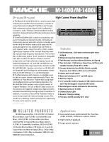
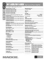
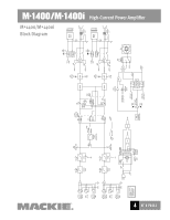
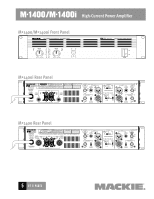
M•1400/M•1400i High-Current Power Amplifer Architects' and Engineers' Specifications 1. GENERAL. The amplifier shall have a free-standing frame with front and rear brackets for rack-mounting, and supplied with four resilient feet suitable for tabletop placement. The amplifier shall be capable of twochannel operation, with a switch to place the amplifier into single-channel operation by bridging the outputs of the two channels. 2. POWER OUTPUT. The two-channel power amplifier shall deliver a rated continuous average sine wave power output over a 20Hz to 20kHz bandwidth of 250 watts RMS into 8 ohms per channel, 425 watts into 4 ohms, and 630 watts into 2 ohms with both channels operating, with no more than 0.05% total harmonic distortion. In single-channel operation it shall deliver 850 watts RMS into 8 ohms and 1260 watts into 4 ohms, with no more than 0.05% total harmonic distortion. The power amplifier shall deliver a maximum continuous average sine wave power output at mid-band of 300 watts RMS into 8 ohms per channel, 500 watts into 4 ohms, and 700 watts into 2 ohms with both channels operating, with no more than 1% total harmonic distortion. In single-channel operation it shall deliver 1000 watts RMS into 8 ohms and 1400 watts into 4 ohms, with no more than 1% total harmonic distortion. 3. POWER SUPPLIES. All necessary operating voltages for the amplifier shall be provided by an internal power supply. A master power switch shall be located on the front panel along with a green power-indicating light. 4. INPUT CHANNEL CONNECTIONS. Each monaural input channel shall have an electronically balanced linelevel input, presenting no less than a 20k ohm impedance to the source. Each input shall have an input sensitivity of +4 dBu, requiring no more than 1.23V RMS to be driven to rated output into a 4 ohm load. The input connector shall appear on the rear panel as a female XLR-3 type connector. In addition, each monaural input channel shall have a parallel 1/4" TRS phone jack and a male XLR-3 type connector, which can be used as inputs or "thru" jacks for daisy-chaining the input signal to another amplifier. Pin 2 of the XLR connectors, and the tip of the 1/4" TRS phone jack, shall be non-inverting. 5. INPUT CHANNEL LEVEL CONTROLS. Each monaural input channel shall be equipped with a gain control appearing on the front panel, each having 20 detent positions, and calibrated in dB and volts. 6. FRONT PANEL INDICATORS. Each channel shall have an associated six-segment LED meter appearing on the front panel, capable of displaying signal present, -20 dB, -9 dB, -6 dB, -3 dB, and overload. Each channel shall have internal status LEDs appearing on the front panel to indicate activation of protect mode and short-circuit protection. Two temperature status LEDs shall appear on the front panel, one to indicate normal operation (COLD) and one to indicate thermal protection (HOT). 7. PROTECTION FEATURES. The amplifier shall provide delayed activation of the outputs at turn-on. Each channel shall have a short-circuit protection circuit for detecting excessive current flow at the output that, when activated, mutes the output for four seconds. The shortcircuit protection shall continuously cycle on and off until the shorted condition is remedied. The amplifier shall have a thermal protection circuit to protect the power devices from over-temperature operation. The circuit shall activate when the internal temperature crosses the safeoperating threshold and, when activated, mute the outputs until the internal temperature cools to a safe-operating temperature, at which time amplifier shall resume normal operation. The amplifier shall have a fan to cool the heat-producing internal components, drawing cool air in from the front, and exhausting warm air out through both sides. The fan shall operate at two speeds, the speed being determined by the internal temperature and the signal level present at the output. The amplifier shall have an SCR crowbar circuit to protect the speakers against a catastrophic amplifier failure. The circuit shall activate in the presence of continuous DC at the speaker outputs, and shall shut the amplifier down by turning off the high-voltage rails. 8. OUTPUT CONNECTIONS. M•1400i: Each channel shall have a heavy-duty 5-way binding post speaker output connector appearing on the rear panel, with 3/4" spacing for accommodating standard double banana plugs as well as spade lugs or bare wires. Each channel shall have a 1/4" TS phone speaker output jack appearing on the rear panel in parallel with the binding post. M•1400: Each channel shall have a heavy-duty 5-way binding post speaker output connector appearing on the rear panel, with 3/4" spacing for accommodating standard double banana plugs (120V versions only) as well as spade lugs or bare wires. Each channel shall have a Neutrik brand Speakon® speaker output jack appearing on the rear panel in parallel with the binding post output. 9. AMP MODES. The amplifier shall have a three-way switch appearing on the rear panel for selecting the mode of operation, which shall include stereo (two channels in, two channels out), mono (one channel in, two channels out), and bridge (one channel in, one channel out, bridged between both speaker outputs). 10. OUTPUT APPLICATIONS. The amplifier shall have a three-way switch appearing on the rear panel for (continued on page 7) 6 OF 8 PAGES
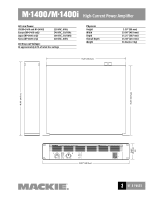
-
 1
1 -
 2
2 -
 3
3 -
 4
4 -
 5
5 -
 6
6 -
 7
7 -
 8
8
 |
 |