Magnavox 50MF231D User manual, English (US) - Page 24
Connect Accessory Device
 |
View all Magnavox 50MF231D manuals
Add to My Manuals
Save this manual to your list of manuals |
Page 24 highlights
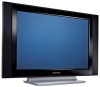
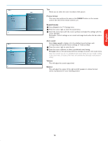
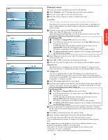
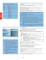
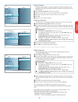
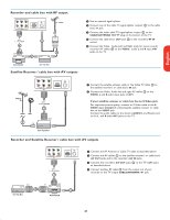
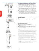
Español Française English Connect Accessory Devices Recorder (VCR / DVD+RW) AUDIO IN VIDEO IN AV1 AV1 : L + R + VIDEO CABLE 3 OUT IN OUT RECORDER Recorder and other A/V devices file : conn us top05 vcr -tv g.eps AUDIO IN VIDEO IN AV2 AUDIO IN VIDEO IN AV1 CABLE AV2 : L + R + VIDEO AV1 : L + R + VIDEO 1 3 5 4 IN OUT IN 2 OUT OUT RECORDER Clear region ratings This function allows you to clear all the Region Ratings settings. & Select Clear region ratings with the cursor down. é Press the cursor right to enter the list. You are asked to enter your code. (See below). Set/Change PIN & Select Set or Change PIN with the cursor down. é If no PIN-code exists yet, the menu item is set to Set PIN. Follow the instructions on screen. If a PIN-code has previously been entered, the menu item is set to Change PIN. Follow the instructions on screen. All number combinations from 0000 to 9999 are valid numbers. " The Menu preferences menu reappears with a message confirming that the PIN has been created. " Select Start now. ' Press OK to activate. Note: - The above 2 features (Region ratings lock and Clear region ratings) will be available only in sets manufactured after the cut-off timeline, specified by the FCC mandate. Note: Do not place your recorder too close to the screen as some recorders may be susceptible for signals from the display. Keep a minimum distance of 20" from the screen. & Connect the RF Antenna or Cable TV cable (eventually via an optional two-way signal splitter and/or Cable TV converter box) 1 to the RF IN socket of your recorder. é Connect another RF cable 2 from the output OUT of your recorder to the TV's CABLE/ANTENNA 75 Ω x jack. " Better playback quality can be obtained if you also connect the Video, Audio Left and Right (only for stereo devices) AV cables 3 to the VIDEO, AUDIO L and R input jacks of AV1. If your recorder has an S-VHS video jack: For improved picture quality, connect an S-video cable to the S-VIDEO input of AV3 instead of connecting the recorder to the VIDEO jack of AV1. S-Video does not provide audio, so audio cables must still be connected to Audio L and R of AV3 to provide sound. & Connect the RF antenna cable 1 of the RF IN socket of your other AV device. é Connect the RF output of the AV device to the RF input of the recorder 2. " Connect another RF cable 4 from the output OUT of your recorder to the TV's input CABLE/ANTENNA 75 Ω x jack. ' To obtain better quality, also connect the Video, Audio left and Audio right cables of both devices to AV1 (VIDEO and AUDIO L and R,) 5 and to AV2 (VIDEO and AUDIO L and R) 3. Notes: - In case of mono equipment, only the left loudspeaker reproduces sound. Use a mono to stereo adapter (not supplied) for sound reproduction via all internal loudspeakers. - When using the S-VIDEO connector do not connect any device to the AV3 VIDEO input. 20
-
 1
1 -
2
-
3
-
4
-
5
-
6
-
7
-
8
-
9
-
10
-
11
-
12
-
13
-
14
-
15
-
16
-
17
-
18
-
 19
19 -
 20
20 -
 21
21 -
 22
22 -
 23
23 -
 24
24 -
 25
25 -
 26
26 -
 27
27 -
 28
28 -
 29
29 -
30
-
31
-
32
-
33
-
34
-
35
 |
 |