Magnavox MDV453 User Manual - Page 9
Hookups cont
 |
UPC - 037849937457
View all Magnavox MDV453 manuals
Add to My Manuals
Save this manual to your list of manuals |
Page 9 highlights
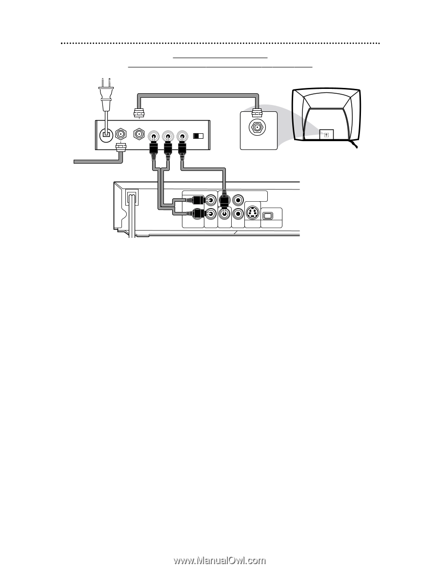
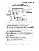
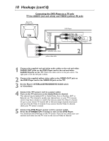
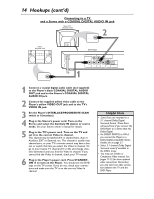
Hookups (cont'd) 9 Connecting to a TV Only TV has only a single ANTENNA IN or RF-IN jack Back of TV (example only) 4 Back of RF Modulator (example only) ANT IN TO TV AUDIO IN R L VIDEO IN 5 CH3 CH4 3 Antenna or 2 1 Cable TV Signal ANTENNA IN RF IN DVD Player 7 AUDIO OUT L DIGITAL AUDIO OUT PCM / BITSTREAM Y Pr/Cr COMPONENT VIDEO OUT IP COAXIAL R VIDEO Pb/Cb S-VIDEO PROGRESSIVE OUT OUT 6 Before you begin, make sure you have an RF modulator and extra RF coaxial cables. These are not supplied with the Player, but are available from Magnavox or most consumer electronics retailers. 1 Connect the supplied video cable (yellow) to the Player's yellow VIDEO OUT jack and to the VIDEO IN jack on the RF modulator. The VIDEO IN jack on the RF modulator is usually yellow and might be labelled VIDEO, CVBS, COMPOSITE, or BASEBAND. 2 Connect the supplied audio cable (red and white) to the Player's red and white AUDIO OUT (left and right) jacks. Connect the other ends of the audio cable to the AUDIO IN jacks on the RF modulator. Audio jacks on the RF modulator usually are red (right) and white (left). Match the cable colors to the jack colors. 3 You probably already have an Antenna or Cable TV signal connected to the ANTENNA IN jack on your TV. Disconnect it now from the TV. Reconnect the Antenna or Cable TV signal to the ANTENNA IN jack on your RF modulator. 4 Connect an RF coaxial cable (not supplied) to the RF OUT, ANTENNA OUT, or TO TV jack on the RF modulator. The RF OUT jack may be labelled differently among different brands. Refer to the instructions provided with your RF modulator. Connect the other end of the same RF coaxial cable to the ANTENNA IN or RF IN jack on your Television. 5 Your RF Modulator should have a Channel 3/4 switch. The setting of this switch determines the TV channel on which you will watch materials playing on the DVD Player. Set the RF Modulator's Channel 3/4 switch to either 3 or 4, whichever TV channel is least used in your area. If your RF modulator has a Modulator/Antenna switch, set it accordingly. Refer to the instructions that came with the RF Modulator. Turn on your TV and choose channel 3 or 4. Choose the same channel to which you set the RF Modulator's Channel 3/4 switch. 6 Set the Player's INTERLACE/PROGRESSIVE SCAN switch to I (interlace). 7 Connect the Player's power cord to a power outlet. Press STANDBY-ON y to turn on the Player. If no Disc is in the Player, you should see the DVD logo on the TV screen.
-
 1
1 -
2
-
3
-
 4
4 -
 5
5 -
 6
6 -
 7
7 -
 8
8 -
 9
9 -
 10
10 -
 11
11 -
 12
12 -
 13
13 -
 14
14 -
15
-
16
-
17
-
18
-
19
-
20
-
21
-
22
-
23
-
24
-
25
-
26
-
27
-
28
-
29
-
30
-
31
-
32
-
33
-
34
-
35
-
36
-
37
-
38
-
39
-
40
-
41
-
42
-
43
-
44
-
45
-
46
-
47
-
48
 |
 |