Magnavox ZC320MW8 Owners Manual - Page 14
Connection To An External Tuner - code
 |
View all Magnavox ZC320MW8 manuals
Add to My Manuals
Save this manual to your list of manuals |
Page 14 highlights
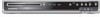
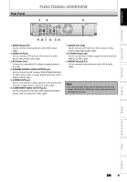
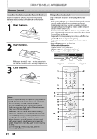
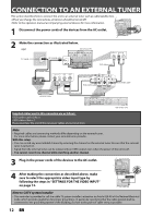
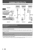
CONNECTION TO AN EXTERNAL TUNER This section describes how to connect this unit to an external tuner such as cable/satellite box. • When you change the connections, all devices shouldVbHFe/ tUuHFrned off. • Refer to the operation manual accompanying externaladnteenvniaces for more information. 2 1 Disconnect the power cords of the devices from the ACDoiscuontnlecet t. or RF coaxial cable ANT. IN Cable TV company rear of your TV disconnect 2 Make the connection as illustrated below. e.g.) rear of your TV TV signal RF coaxial cable VIDEO IN AUDIO IN R L ANT. IN RCA video cable RF coaxial cable AUDIO OUT R L VIDEO S-VIDEO OUT OUT IN OUT or RCA video cable VIDEO VIDEO OUT IN Y IN PB / CB L L RCA audio cable R AUDIO IN (E1) R PR / CR S-VIDEO AUDIO OUT COMPONENT VIDEO OUTPUT RCA audio cable external tuner S-video cable VIDEO VIDEO OUT IN IN L L Y DIGITAL AUDIO PB / CB OUT OUTPUT PCM/BITSTREAM R AUDIO IN (E1) PR / R CR S-VIDEO AUDIO OUT COMPONENT VIDEO OUTPUT COAXIAL S-VIDEO rear of this unit Supplied cables used in this connection are as follows: • RCA audio cable (L/R) x 1 • RCA video cable x 1 Please purchase the rest of the necessary cables at your local store. Note • Required cables and connecting methods differ depending on the external tuner. For more information, please contact your external tuner provider. With this setup: • You can record any unscrambled channel by selecting the channel on the external tuner. Be sure that the external tuner is turned on. • Signal from the external tuner can be output only on CVBS output even when the power of the unit is off. • You cannot record one channel while watching another channel. 3 Plug in the power cords of the devices to the AC outlet. rear of your TV 4 After making the connection as described above, make sure to select the appropriate video input type by VIDEO VIDEO OUT following the steps in "SETTINGS FOR THE VIDEO INPUT"IN IN L L Y DIGITAL AUDIO PB / CB OUT OUTPUT PCM/BITSTREAM on page 13. R AUDIO IN (E1) R PR / CR S-VIDEO AUDIO OUT COMPONENT VIDEO OUTPUT COAXIAL S-VIDEO connect rear of this unit Note to CATV system installer • This reminder is provided to call the cable TV system installer's attention to Article 820-40 of the National Electrical Code, which provides guidelines for proper grounding - in particular, specifying that the cable ground shall be connected to the grounding system of the building, as close to the point of cable entry as possible. 12 EN
-
 1
1 -
2
-
3
-
4
-
5
-
6
-
7
-
8
-
 9
9 -
 10
10 -
 11
11 -
 12
12 -
 13
13 -
 14
14 -
 15
15 -
 16
16 -
 17
17 -
 18
18 -
 19
19 -
20
-
21
-
22
-
23
-
24
-
25
-
26
-
27
-
28
-
29
-
30
-
31
-
32
-
33
-
34
-
35
-
36
-
37
-
38
-
39
-
40
-
41
-
42
-
43
-
44
-
45
-
46
-
47
-
48
-
49
-
50
-
51
-
52
-
53
-
54
-
55
-
56
-
57
-
58
-
59
-
60
-
61
-
62
-
63
-
64
-
65
-
66
-
67
-
68
-
69
-
70
-
71
-
72
-
73
-
74
-
75
-
76
-
77
-
78
-
79
-
80
-
81
-
82
-
83
-
84
-
85
-
86
-
87
-
88
 |
 |