Magnavox ZV427MG9 User manual, English (US) - Page 13
Connections, CONNECTION TO AN EXTERNAL TUNER
 |
UPC - 053818570722
View all Magnavox ZV427MG9 manuals
Add to My Manuals
Save this manual to your list of manuals |
Page 13 highlights
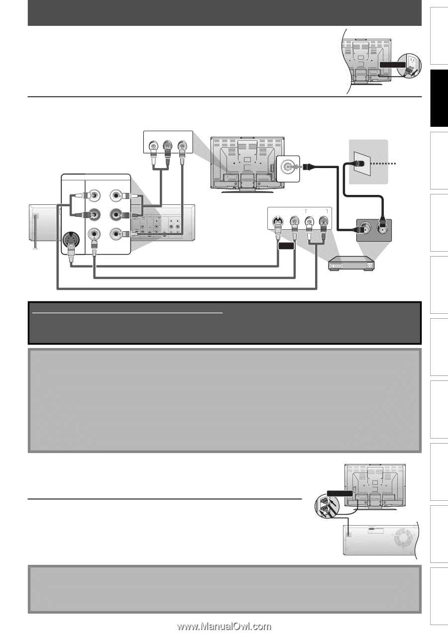
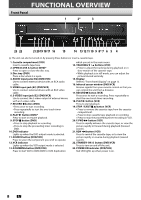
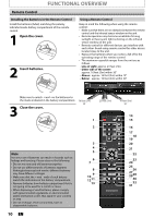
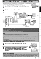
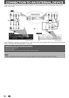
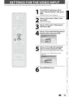
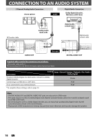
Introduction Connections Basic Setup Recording Playback CONNECTION TO AN EXTERNAL TUNER This section describes how to connect this unit to an external tuner such as cable/satellite box. VHF / UHF • When you change the connections, all devices should banetentnuarned off. • Refer to the manual accompanying external devices for more information. 2 Disconnect 1 Disconnect the power cords of the devices forrom the AC outlet. RF coaxial cable ANT. IN Cable TV company rear of your TV disconnect 2 Make the connection as illustrated below. e.g.) AUDIO IN VIDEO IN L R rear of your TV DVD/VCR S-VIDEO IN ---AUDIO---OUT L RCA audio cable RCA video cable HDMI OUT IN R IN ---VIDEO---OUT DIGITAL AUDIO OUT DVD AUDIO S-VIDEO COMPONENT S-VIDEO OUT VIDEO OUT Y DVD/VCR IN ---AUDIO---OUT L L PB /CB IN PR /CR R R IN ---VIDEO---OUT rear of this unit RF coaxial cable ANT. IN TV signal S-VIDEO VIDEO OUT OUT AUDIO OUT L R RF coaxial cable or S-video cable RCA video cable RCA audio cable OUT IN external tuner Supplied cables used in this connection are as follows: • RCA audio cable (L/R) x 1 • RCA video cable x 1 Please purchase the rest of the necessary cables at your local store. Note • Required cables and connecting methods differ depending on the external tuner. For more information, please contact your external tuner provider. • Instead of using VIDEO OUT jack of this unit, you can also use S-VIDEO OUT jack, COMPONENT VIDEO OUT jack, or HDMI OUT jack (no AUDIO OUT jack connection required) for connecting to your TV. With this setup: • You can record any unscrambled channel by selecting the channel on the external tuner. Be sure that the external tuner is turned on. • Signal from the external tuner can be output only on CVBS output even when the power of the unit is off. • You cannot record one channel while watching another channel. 3 Plug in the power cords of the devices to the AC outlet. rear of your TV connect 4 After making the connection as described above, make sure to select the appropriate video input type by following the steps in "SETTINGS FOR THE VIDEO INPUT" on page 15. rear of this unit HDMI OUT Editing Function Setup VCR Functions Others Español Note to CATV system installer • This reminder is provided to call the cable TV system installer's attention to Article 820-40 of the National Electrical Code, which provides guidelines for proper grounding - in particular, specifying that the cable ground shall be connected to the grounding system of the building, as close to the point of cable entry as possible. EN 13
-
 1
1 -
2
-
3
-
4
-
5
-
6
-
7
-
 8
8 -
 9
9 -
 10
10 -
 11
11 -
 12
12 -
 13
13 -
 14
14 -
 15
15 -
 16
16 -
 17
17 -
 18
18 -
19
-
20
-
21
-
22
-
23
-
24
-
25
-
26
-
27
-
28
-
29
-
30
-
31
-
32
-
33
-
34
-
35
-
36
-
37
-
38
-
39
-
40
-
41
-
42
-
43
-
44
-
45
-
46
-
47
-
48
-
49
-
50
-
51
-
52
-
53
-
54
-
55
-
56
-
57
-
58
-
59
-
60
-
61
-
62
-
63
-
64
-
65
-
66
-
67
-
68
-
69
-
70
-
71
-
72
-
73
-
74
-
75
-
76
-
77
-
78
-
79
-
80
-
81
-
82
-
83
-
84
-
85
-
86
-
87
-
88
-
89
-
90
-
91
-
92
 |
 |