Makita MAC700 Owners Manual - Page 8
Storage, Description Of, Operation - review
 |
View all Makita MAC700 manuals
Add to My Manuals
Save this manual to your list of manuals |
Page 8 highlights
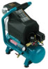
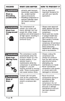
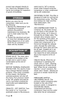
product was shipped directly to you, report any damages to the carrier and arrange for inspection of goods immediately. STORAGE Before you store the air compressor, make sure you do the following: 1. Review the "Maintenance" and "Operating Procedures" sections and perform maintenance as necessary. Be sure to drain water from the air tank. 2. Protect the electrical cord and air hose from damage (such as being stepped on or run over). Store the air compressor in a clean and dry location. DESCRIPTION OF OPERATION DRAIN VALVE: The drain valve is located at the bottom of the air tank and is used to drain condensation at the end of each use. MOTOR THERMAL OVERLOAD PROTECTOR: The electric motor has a manual thermal overload protector. If the motor overheats for any reason, the thermal overload protector will shut off the motor. Turn pressure switch to the "off" position and wait for unit to cool before pushing the reset button and restarting the compressor. ON/AUTO - OFF SWITCH: Turn this switch to "on" to provide automatic power to the pressure Page 8 switch and to "off" to remove power when finished using the compressor or when compressor will be left unattended. AIR INTAKE FILTER: This filter is designed to clean air coming into the compressor pump. This filter must always be clean and free from obstructions. See "Maintenance". AIR COMPRESSOR PUMP: To compress air, the piston moves up and down in the cylinder. On the down stroke, air is drawn in through the air intake valve. The exhaust valve remains closed. On the upstroke of the piston, air is compressed. The intake valve closes and compressed air is forced out through the exhaust valve, through the outlet tube, through the check valve and into the air tank. Useable air is not available until the compressor has raised the air tank pressure above that required at the air outlet. CHECK VALVE: When the air compressor is operating, the check valve is "open", allowing compressed air to enter the air tank. When the air compressor reaches "cut-out" pressure, the check valve "closes", allowing air pressure to remain inside the air tank. PRESSURE SWITCH UNLOADING VALVE: The pressure switch unloading valve located on the side of the pressure switch, is designed to automatically release compressed air from the compressor head and the outlet tube when the air compressor
-
 1
1 -
2
-
 3
3 -
 4
4 -
 5
5 -
 6
6 -
 7
7 -
 8
8 -
 9
9 -
 10
10 -
 11
11 -
 12
12 -
 13
13 -
14
-
15
-
16
-
17
-
18
-
19
-
20
 |
 |