Marantz AV7005 AV7005 User Manual - English - Page 23
Connecting a video cassette recorder, Connecting a digital camcorder
 |
View all Marantz AV7005 manuals
Add to My Manuals
Save this manual to your list of manuals |
Page 23 highlights
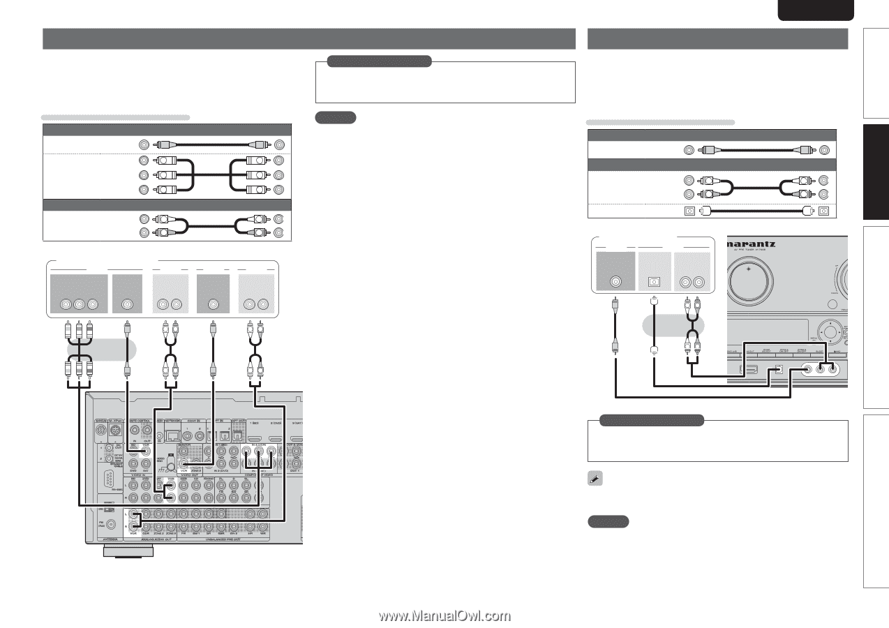
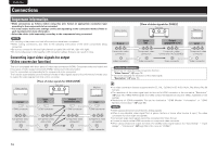
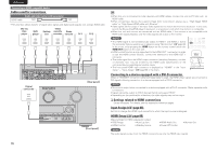
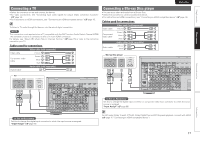
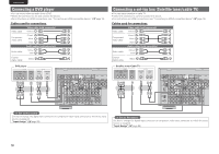
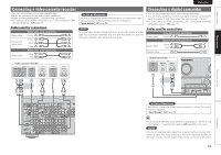
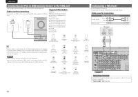
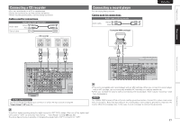
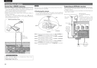
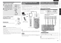
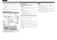
Simple version Basic version SVENSKA NEDERLANDS ESPAÑOL ITALIANO FRANÇAIS DEUTSCH ENGLISH Connecting a video cassette recorder • You can record video onto a video cassette tape. • Select the connector to use and connect the device. • When recording analog audio, use the analog connection. • For instructions on HDMI connections, see "Connecting an HDMI- compatible device" (vpage 15). Cables used for connections Video cable (sold separately) Video cable (Yellow) (Green) Y Y Component video cable (Blue) PB PB (Red) PR PR Audio cable (sold separately) (White) L L Audio cable (Red) R R Video cassette recorder VIDEO COMPONENT VIDEO OUT Y PB PR VIDEO OUT AUDIO AUDIO OUT LR VIDEO VIDEO IN AUDIO AUDIO IN LR in Set as Necessary Set this to change the digital input connector or component video input connector to which the input source is assigned. "Input Assign" (vpage 68) NOTE To record video signals through this unit, use the same type of video cable for connection between this unit and the player as used for connection between this unit and the recorder. Connecting a digital camcorder • You can enjoy video and audio from a digital camcorder. • You can enjoy games by connecting a game machine via the AUX1 input connector. In this case, select the input source to "AUX1". • For instructions on HDMI connections, see "Connecting an HDMI- compatible device" (vpage 15). Cables used for connections Video cable (sold separately) Video cable (Yellow) Audio cable (sold separately) (White) L L Audio cable (Red) R R Optical cable Digital camcorder VIDEO VIDEO OUT AUDIO OPTICAL OUT AUDIO OUT LR LR LR LR LR LR LR Advanced version Information in Set as Necessary Set this to change the digital input connector to which the input source is assigned. "Input Assign" (vpage 68) The front panel OPTICAL input terminal is displayed as "OPT3" in the "Input Setup" - "Input Assign" setting (vpage 68) in the menu. NOTE When a non-standard video signal from a game machine or some other source is input, the video conversion function might not operate. In this case, use the monitor output of the same connector as the input. 19
-
 1
1 -
2
-
3
-
4
-
5
-
6
-
7
-
8
-
9
-
10
-
11
-
12
-
13
-
14
-
15
-
16
-
17
-
 18
18 -
 19
19 -
 20
20 -
 21
21 -
 22
22 -
 23
23 -
 24
24 -
 25
25 -
 26
26 -
 27
27 -
 28
28 -
29
-
30
-
31
-
32
-
33
-
34
-
35
-
36
-
37
-
38
-
39
-
40
-
41
-
42
-
43
-
44
-
45
-
46
-
47
-
48
-
49
-
50
-
51
-
52
-
53
-
54
-
55
-
56
-
57
-
58
-
59
-
60
-
61
-
62
-
63
-
64
-
65
-
66
-
67
-
68
-
69
-
70
-
71
-
72
-
73
-
74
-
75
-
76
-
77
-
78
-
79
-
80
-
81
-
82
-
83
-
84
-
85
-
86
-
87
-
88
-
89
-
90
-
91
-
92
-
93
-
94
-
95
-
96
-
97
-
98
-
99
-
100
-
101
-
102
-
103
-
104
-
105
-
106
-
107
-
108
-
109
-
110
-
111
-
112
-
113
-
114
-
115
-
116
-
117
-
118
-
119
-
120
-
121
-
122
-
123
-
124
-
125
-
126
-
127
-
128
 |
 |