Maytag MAH5500BWW Service Manual - Page 116
Input Modifications Defined
 |
View all Maytag MAH5500BWW manuals
Add to My Manuals
Save this manual to your list of manuals |
Page 116 highlights
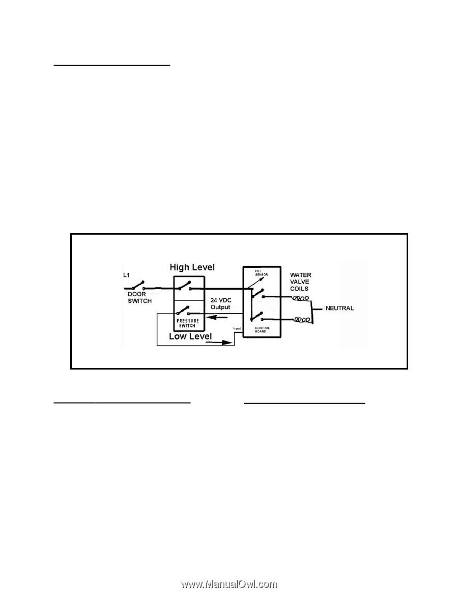
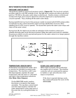
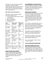
INPUT MODIFICATIONS DEFINED PRESSURE SWITCH INPUT The pressure switch is a two level pressure switch. (Figure 4-2) The low level contacts provide a path for a 24 VDC sensing circuit, the high level contacts provide an electrical path for 110 VAC to the water valve relays on the board. Another sensor on the board monitors the high level circuit to determine when the high level is reached and the circuit is opened. Thus, shutting off the water valve relays. During wash fill, the low level of the pressure switch is sensed with 24 VDC and provides an indication to the control board the water level has satisfied the low level. Once satisfied, the 24 VDC circuit is opened. The board then opens the water valve relays and shuts off the water valves. During rinse fill, the high level provides an indication to the machine control as to whether the high water level has been reached. When the water level switch is satisfied, the pressure switch circuit is opened and power for the water valves is no longer passed through the machine control. Figure 2 TEMPERATURE SENSOR INPUT DOOR LOCK SWITCH INPUT A thermistor is located in the water valve When input is present, this is indication to monitor the blended incoming water the washer door is locked. The machine temperature. The machine control uses controller will not command the spinner this input signal to regulate the water to tumble or spin when the door lock temperature with the warm or cold wash input is not present. and warm rinse temperature selections (See Water Valve Outputs). If the door is opened during a cycle, the control will pause the cycle on the On the MAH7500 model, another MAH5500B. thermistor is located on the heater assembly. The machine control board uses this input signal to maintain the water temperature in the sump area of the outer tub, by cycling the heater on/ off. 16010486 (16008373-05) Revised 02/01 Section 2. Washer Controls Overview ©2001 Maytag Appliances Sales Company 2-4
-
 1
1 -
2
-
3
-
4
-
5
-
6
-
7
-
8
-
9
-
10
-
11
-
12
-
13
-
14
-
15
-
16
-
17
-
18
-
19
-
20
-
21
-
22
-
23
-
24
-
25
-
26
-
27
-
28
-
29
-
30
-
31
-
32
-
33
-
34
-
35
-
36
-
37
-
38
-
39
-
40
-
41
-
42
-
43
-
44
-
45
-
46
-
47
-
48
-
49
-
50
-
51
-
52
-
53
-
54
-
55
-
56
-
57
-
58
-
59
-
60
-
61
-
62
-
63
-
64
-
65
-
66
-
67
-
68
-
69
-
70
-
71
-
72
-
73
-
74
-
75
-
76
-
77
-
78
-
79
-
80
-
81
-
82
-
83
-
84
-
85
-
86
-
87
-
88
-
89
-
90
-
91
-
92
-
93
-
94
-
95
-
96
-
97
-
98
-
99
-
100
-
101
-
102
-
103
-
104
-
105
-
106
-
107
-
108
-
109
-
110
-
 111
111 -
 112
112 -
 113
113 -
 114
114 -
 115
115 -
 116
116 -
 117
117 -
 118
118 -
 119
119 -
 120
120 -
 121
121 -
122
-
123
-
124
-
125
-
126
-
127
-
128
-
129
-
130
-
131
-
132
-
133
-
134
-
135
-
136
-
137
-
138
-
139
-
140
-
141
-
142
-
143
-
144
-
145
-
146
-
147
-
148
-
149
-
150
-
151
-
152
-
153
-
154
-
155
-
156
-
157
 |
 |