Maytag MAH5500BWW Service Manual - Page 12
Input Definitions - won t start
 |
View all Maytag MAH5500BWW manuals
Add to My Manuals
Save this manual to your list of manuals |
Page 12 highlights
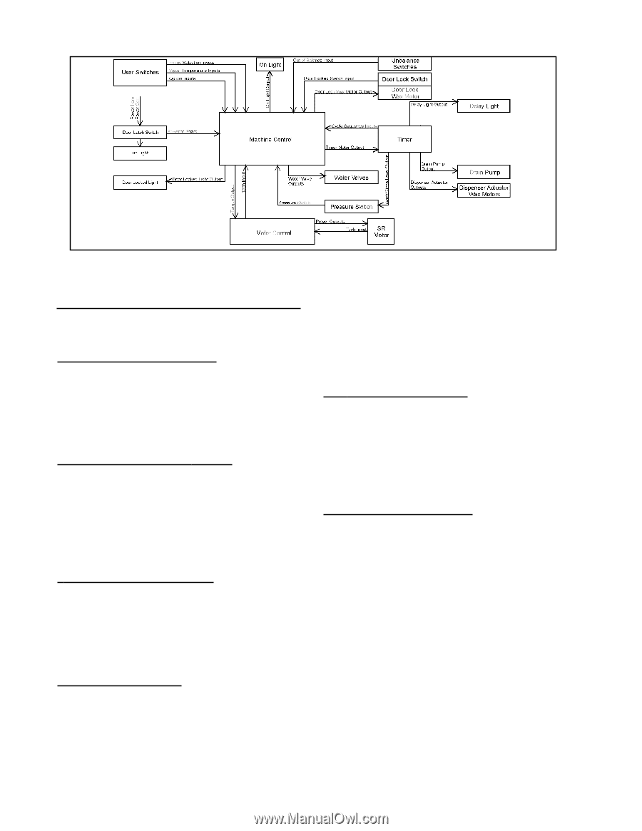
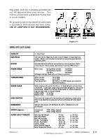
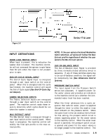
Figure 1-8 Series 17 & Later INPUT DEFINITIONS DOOR LOCK SWITCH INPUT When input is present, this is indication the washer door is locked. The machine controller will not command the spinner to spin faster than 50 rpm when the input is not present prior to spin. END-OF-CYCLE SIGNAL INPUT The End-of-Cycle Signal Input is energized through a user input switch on the control panel. When this is energized and the cycle has finished, the machine control will sound the End-of-Cycle signal (See End-Of-Cycle Signal Output). FABRIC SELECTION INPUTS The Fabric Selection Inputs are energized through a user input switch on the control panel. The machine control reads these inputs to determine which cycles should be run when the washer is started. MAX EXTRACT INPUT The Max Extract Input is energized through a user input switch on the control panel. When input is energized, the machine control will modify the final spin profile to the max extract profile. NOTE: If the user selects the Hand Washables fabric selection, all spins will follow the Max Extract profile regardless of whether the user selects the Max Extract option. OUT-OF-BALANCE INPUT The Out-of-Balance Input Signal is provided by three normally-closed switches wired in sequence. If any of these switches opens due to an out-of-balance condition, the signal will be momentarily lost (See Unbalance Control System). PRESSURE SWITCH INPUT The input signal from the Pressure Switch serves two purposes. It supplies power for the water valves and provides an indication to the machine control as to whether the commanded water level has been reached. When the timer advances into a cycle sequence that calls for water, power is supplied through the timer to either the wash or rinse level contacts on the pressure switch. When the water level in the tub is below the full level for that setting, the pressure switch circuit is closed, supplying power for the water valves to the machine control. When the water level switch is satisfied, the pressure switch circuit is opened and power for the water valves is no longer passed to the machine control. The 16008373-01 © 1998 Maytag Corporation SECTION 1. GENERAL INFORMATION 1-6
-
 1
1 -
2
-
3
-
4
-
5
-
6
-
 7
7 -
 8
8 -
 9
9 -
 10
10 -
 11
11 -
 12
12 -
 13
13 -
 14
14 -
 15
15 -
 16
16 -
 17
17 -
18
-
19
-
20
-
21
-
22
-
23
-
24
-
25
-
26
-
27
-
28
-
29
-
30
-
31
-
32
-
33
-
34
-
35
-
36
-
37
-
38
-
39
-
40
-
41
-
42
-
43
-
44
-
45
-
46
-
47
-
48
-
49
-
50
-
51
-
52
-
53
-
54
-
55
-
56
-
57
-
58
-
59
-
60
-
61
-
62
-
63
-
64
-
65
-
66
-
67
-
68
-
69
-
70
-
71
-
72
-
73
-
74
-
75
-
76
-
77
-
78
-
79
-
80
-
81
-
82
-
83
-
84
-
85
-
86
-
87
-
88
-
89
-
90
-
91
-
92
-
93
-
94
-
95
-
96
-
97
-
98
-
99
-
100
-
101
-
102
-
103
-
104
-
105
-
106
-
107
-
108
-
109
-
110
-
111
-
112
-
113
-
114
-
115
-
116
-
117
-
118
-
119
-
120
-
121
-
122
-
123
-
124
-
125
-
126
-
127
-
128
-
129
-
130
-
131
-
132
-
133
-
134
-
135
-
136
-
137
-
138
-
139
-
140
-
141
-
142
-
143
-
144
-
145
-
146
-
147
-
148
-
149
-
150
-
151
-
152
-
153
-
154
-
155
-
156
-
157
 |
 |