Maytag MAH5500BWW Service Manual - Page 141
ELECTRICAL TESTS, Grounded Components, Water Valve Test, Door Lock Test - repairs
 |
View all Maytag MAH5500BWW manuals
Add to My Manuals
Save this manual to your list of manuals |
Page 141 highlights
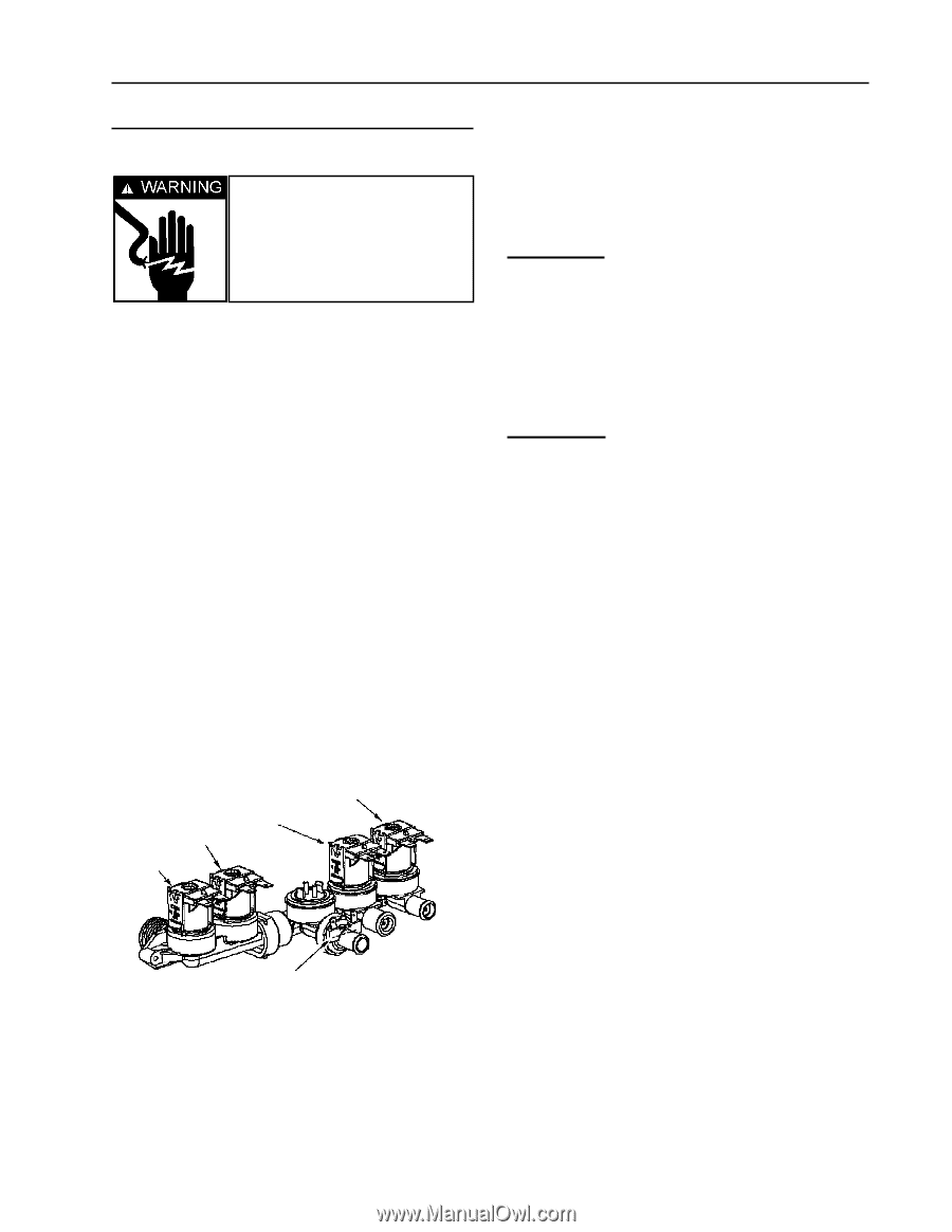
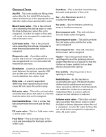
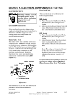
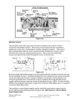
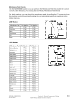
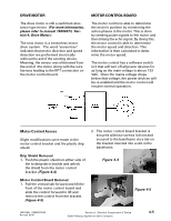
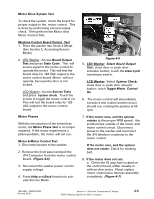
SECTION 4. ELECTRICAL COMPONENTS & TESTING ELECTRICAL TESTS Door Lock Test Warning - Always shut off electrical power to the washer before beginning any service repair procedures. Grounded Components When performing service diagnostics, replacements and repairs, always check to determine whether all ground wires linking panel and components are reattached if removed. Water Valve Test The water valve test is similar to the test outlined in the 16008373 manual, except, to check the ohm resistance of thermistor, pull the P3 wire harness connector off the machine control and locate the P3(6) and P3(7) leads in the connector on the machine control board. Note the thermistor has been relocated on the valve to the outlet of the valve. (See Figure 4-1) Fabric Softner Bleach Cold Hot The door lock can be verified by the following procedure. LED Model 1. Place the washer into Service Mode. (See Section 2; Accessing Service Mode) 2. Advance to the Board Output Test and press Max Extract to Lock the door and Extra Rinse to Unlock the door. LCD Model 1. Place the washer into Service Mode. (See Section 2; Accessing Service Mode) 2. Select Service Tests, then Quick Spin Tests to actuate the door lock mechanism. Hit Cancel to unlock the door. Note: The relay on the control board for the door lock mechanism is disabled if the motor control board indicates the spinner speed is > 7 RPM. For more information related to door lock mechanism, please refer to Section 2: Miscellaneous; Door Lock Philosophy. Thermistor 4 Coil Water Valve Figure 4-1 The thermistor is on NTC and will drop in resistance when the temperature increases. 16010486 (16008373-05) Revised 02/01 Section 4. Electrical Components & Testing ©2001 Maytag Appliances Sales Company 4-1
-
 1
1 -
2
-
3
-
4
-
5
-
6
-
7
-
8
-
9
-
10
-
11
-
12
-
13
-
14
-
15
-
16
-
17
-
18
-
19
-
20
-
21
-
22
-
23
-
24
-
25
-
26
-
27
-
28
-
29
-
30
-
31
-
32
-
33
-
34
-
35
-
36
-
37
-
38
-
39
-
40
-
41
-
42
-
43
-
44
-
45
-
46
-
47
-
48
-
49
-
50
-
51
-
52
-
53
-
54
-
55
-
56
-
57
-
58
-
59
-
60
-
61
-
62
-
63
-
64
-
65
-
66
-
67
-
68
-
69
-
70
-
71
-
72
-
73
-
74
-
75
-
76
-
77
-
78
-
79
-
80
-
81
-
82
-
83
-
84
-
85
-
86
-
87
-
88
-
89
-
90
-
91
-
92
-
93
-
94
-
95
-
96
-
97
-
98
-
99
-
100
-
101
-
102
-
103
-
104
-
105
-
106
-
107
-
108
-
109
-
110
-
111
-
112
-
113
-
114
-
115
-
116
-
117
-
118
-
119
-
120
-
121
-
122
-
123
-
124
-
125
-
126
-
127
-
128
-
129
-
130
-
131
-
132
-
133
-
134
-
135
-
 136
136 -
 137
137 -
 138
138 -
 139
139 -
 140
140 -
 141
141 -
 142
142 -
 143
143 -
 144
144 -
 145
145 -
 146
146 -
147
-
148
-
149
-
150
-
151
-
152
-
153
-
154
-
155
-
156
-
157
 |
 |