Maytag MAH5500BWW Service Manual - Page 142
Machine Control,
 |
View all Maytag MAH5500BWW manuals
Add to My Manuals
Save this manual to your list of manuals |
Page 142 highlights
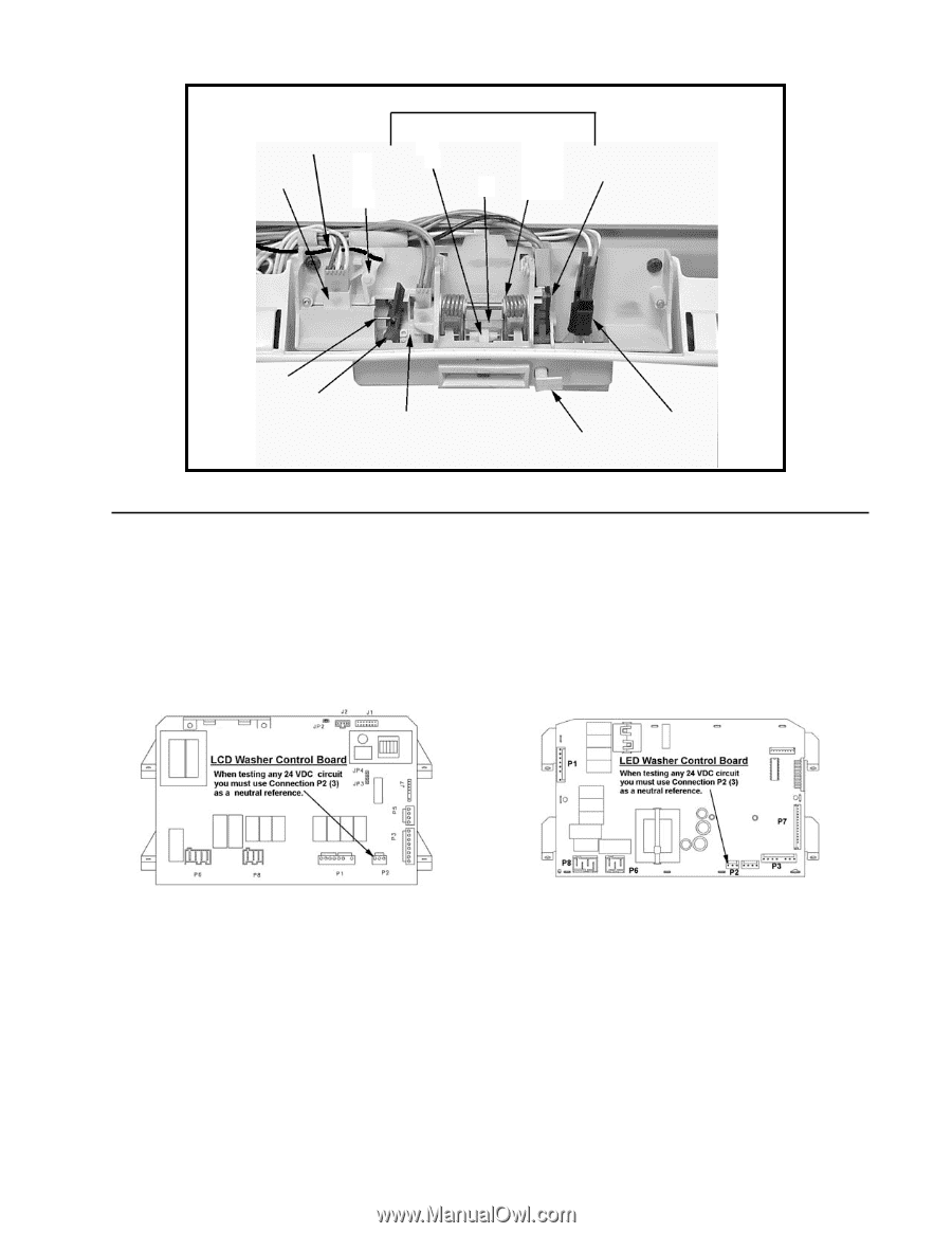
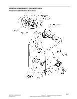
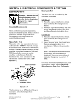
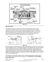
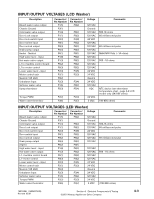
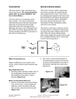
DOOR LOCK MECHANISM Door Emergency Cord Rotating Cam Lock/Unlock Solenoid Mechanical Opener Cam Support Door Lock Spring Door Open/ Closed Switch Solenoid Push-Rod Locking Lever Door Lock/ Unlock Switch Lamp Socket Door Actuator & Lamp Figure 4-2 Machine Control The machine control microprocessor board is located in the control console, mounted to the plastic console. The board receives input from the membrane pad/touch screen, door lock switches, and the unbalance switches. The control also communicates with the motor control board to facilitate the various cycles and drive the motor for optimum performance. This is done by monitoring torque and speed of the motor through the motor control board. Figure 4-3 Both incoming and exiting voltage is monitored through the machine control board and the surrounding circuitry. The following table lists the voltages for the various terminals on the microprocessor board. If proper voltage is not present, check switches and wiring for possible loose connections or open circuits by disconnecting the power supply and performing continuity checks of individual circuits. NOTE: Connector P8(2) (White wire) is Neutral input and L1 input is the connector P6(2) (Black wire), L1 output is connector P6(3) (Black wire). The machince control board outputs can be verified by placing the washer into the Service Mode and performing a Board Output Test. (See Section 2; Service Mode; Board Output Test.) 16010486 (16008373-05) Revised 02/01 Section 4. Electrical Components & Testing ©2001 Maytag Appliances Sales Company 4-2
-
 1
1 -
2
-
3
-
4
-
5
-
6
-
7
-
8
-
9
-
10
-
11
-
12
-
13
-
14
-
15
-
16
-
17
-
18
-
19
-
20
-
21
-
22
-
23
-
24
-
25
-
26
-
27
-
28
-
29
-
30
-
31
-
32
-
33
-
34
-
35
-
36
-
37
-
38
-
39
-
40
-
41
-
42
-
43
-
44
-
45
-
46
-
47
-
48
-
49
-
50
-
51
-
52
-
53
-
54
-
55
-
56
-
57
-
58
-
59
-
60
-
61
-
62
-
63
-
64
-
65
-
66
-
67
-
68
-
69
-
70
-
71
-
72
-
73
-
74
-
75
-
76
-
77
-
78
-
79
-
80
-
81
-
82
-
83
-
84
-
85
-
86
-
87
-
88
-
89
-
90
-
91
-
92
-
93
-
94
-
95
-
96
-
97
-
98
-
99
-
100
-
101
-
102
-
103
-
104
-
105
-
106
-
107
-
108
-
109
-
110
-
111
-
112
-
113
-
114
-
115
-
116
-
117
-
118
-
119
-
120
-
121
-
122
-
123
-
124
-
125
-
126
-
127
-
128
-
129
-
130
-
131
-
132
-
133
-
134
-
135
-
136
-
 137
137 -
 138
138 -
 139
139 -
 140
140 -
 141
141 -
 142
142 -
 143
143 -
 144
144 -
 145
145 -
 146
146 -
 147
147 -
148
-
149
-
150
-
151
-
152
-
153
-
154
-
155
-
156
-
157
 |
 |