Maytag MAH5500BWW Service Manual - Page 149
Teardown & Wiring Information
 |
View all Maytag MAH5500BWW manuals
Add to My Manuals
Save this manual to your list of manuals |
Page 149 highlights
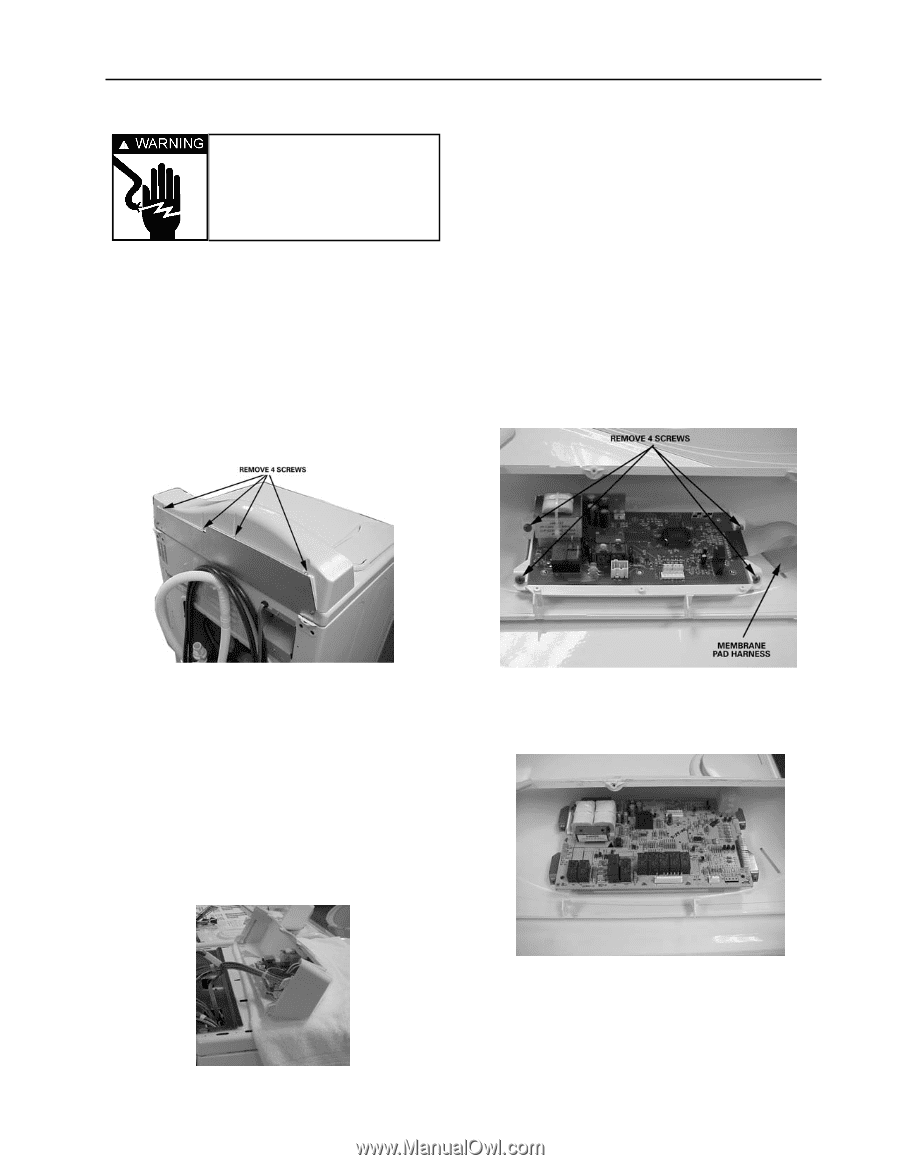
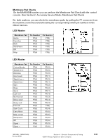
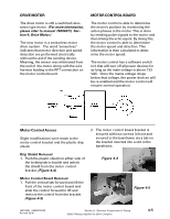
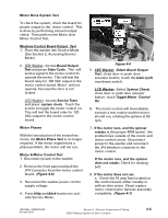
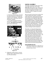
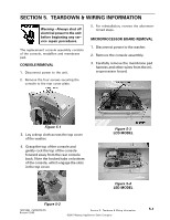
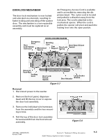
SECTION 5. TEARDOWN & WIRING INFORMATION Warning - Always shut off electrical power to the unit before beginning any service repair procedures. The replacement console assembly consists of the console, medallion and membrane pad. CONSOLE REMOVAL 1. Disconnect power to the unit. 2. Remove the four screws securing the console to the rear cover plate. 5. For reinstallation, reverse the aforementioned steps. MICROPROCESSOR BOARD REMOVAL 1. Disconnect power to the washer. 2. Remove the console assembly. 3. Carefully remove the membrane pad harness and other wires from the microprocessor board. Figure 5-1 3. Lay a drop cloth across the top cover of the washer. 4. Grasp the top of the console and gently rock the top of the console forward away from the rear console back. Note the hooked tabs on bottom of the console, which engage the slots in the top cover. Figure 5-3 LCD MODEL Figure 5-4 LED MODEL Figure 5-2 16010486 (16008373-05) Revised 10/00 Section 5. Teardown & Wiring Information ©2001 Maytag Appliances Sales Company 5-1
-
 1
1 -
2
-
3
-
4
-
5
-
6
-
7
-
8
-
9
-
10
-
11
-
12
-
13
-
14
-
15
-
16
-
17
-
18
-
19
-
20
-
21
-
22
-
23
-
24
-
25
-
26
-
27
-
28
-
29
-
30
-
31
-
32
-
33
-
34
-
35
-
36
-
37
-
38
-
39
-
40
-
41
-
42
-
43
-
44
-
45
-
46
-
47
-
48
-
49
-
50
-
51
-
52
-
53
-
54
-
55
-
56
-
57
-
58
-
59
-
60
-
61
-
62
-
63
-
64
-
65
-
66
-
67
-
68
-
69
-
70
-
71
-
72
-
73
-
74
-
75
-
76
-
77
-
78
-
79
-
80
-
81
-
82
-
83
-
84
-
85
-
86
-
87
-
88
-
89
-
90
-
91
-
92
-
93
-
94
-
95
-
96
-
97
-
98
-
99
-
100
-
101
-
102
-
103
-
104
-
105
-
106
-
107
-
108
-
109
-
110
-
111
-
112
-
113
-
114
-
115
-
116
-
117
-
118
-
119
-
120
-
121
-
122
-
123
-
124
-
125
-
126
-
127
-
128
-
129
-
130
-
131
-
132
-
133
-
134
-
135
-
136
-
137
-
138
-
139
-
140
-
141
-
142
-
143
-
 144
144 -
 145
145 -
 146
146 -
 147
147 -
 148
148 -
 149
149 -
 150
150 -
 151
151 -
 152
152 -
 153
153 -
 154
154 -
155
-
156
-
157
 |
 |