Maytag MAH5500BWW Service Manual - Page 150
Console Cover Plug, Cabinet Assembly, Door Latch Hoop - door latch assembly
 |
View all Maytag MAH5500BWW manuals
Add to My Manuals
Save this manual to your list of manuals |
Page 150 highlights
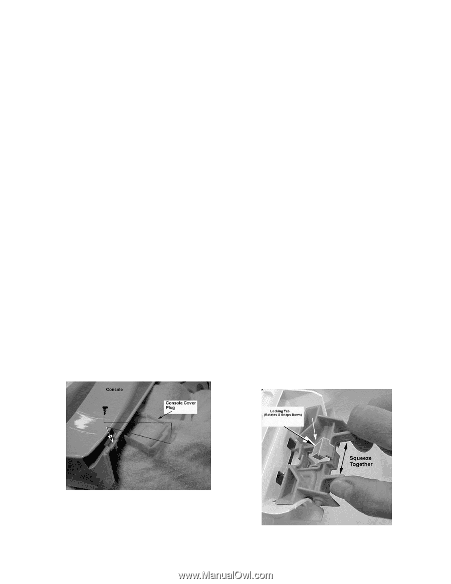
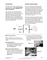
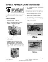
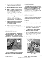
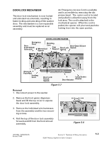
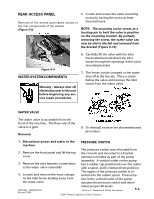
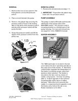
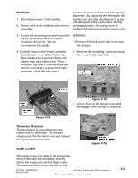
4. Remove the four mounting screws securing the board to the console. 5. Remove the board from the console. 6. Note: To avoid the potential for accidental static discharge damage to the replacement board, you must be properly grounded prior to handling the board. This can be accomplished by using a special grounded strap tied on your wrist and grounded to the product, or simply touching a grounded source to discharge any static charge build up on your person. 7. Insert the replacement board into the console and secure the mounting bracket to the console. 8. Reattach wire harnesses and membrane pad harness to the replacement machine control board. CONSOLE COVER PLUG The cover plug inserts into the rear of the console to fill a cavity void in the console. The plug is secured to the console via a console screw mounted directly behind it. CABINET ASSEMBLY The overall cabinet assembly design is identical to the MAH4000 washer, except for the revised door lock mechanism, door latch hoop and front shroud. for simplicity reasons, we will address only the exceptions in this chapter. DOOR LATCH HOOP The latch hoop was redesigned, eliminating the latch hoop support and spring. REMOVAL 1. Remove the door assembly from the washer. 2. Dissassemble the door assembly by removing the outer door panel. 3. Locate the locking tab on the door latch hoop and pry the tab up. 4. Squeeze the side tabs to disengage the locating pins on the sides of the latch hoop from the door liner. 5. Reinstallation is a reversal of the aforementioned steps. Figure 5-5 The cover plug simply fills a void area in the console for cosmetic purposes only. Figure 5-6 16010486 (16008373-05) Revised 10/00 Section 5. Teardown & Wiring Information ©2001 Maytag Appliances Sales Company 5-2
-
 1
1 -
2
-
3
-
4
-
5
-
6
-
7
-
8
-
9
-
10
-
11
-
12
-
13
-
14
-
15
-
16
-
17
-
18
-
19
-
20
-
21
-
22
-
23
-
24
-
25
-
26
-
27
-
28
-
29
-
30
-
31
-
32
-
33
-
34
-
35
-
36
-
37
-
38
-
39
-
40
-
41
-
42
-
43
-
44
-
45
-
46
-
47
-
48
-
49
-
50
-
51
-
52
-
53
-
54
-
55
-
56
-
57
-
58
-
59
-
60
-
61
-
62
-
63
-
64
-
65
-
66
-
67
-
68
-
69
-
70
-
71
-
72
-
73
-
74
-
75
-
76
-
77
-
78
-
79
-
80
-
81
-
82
-
83
-
84
-
85
-
86
-
87
-
88
-
89
-
90
-
91
-
92
-
93
-
94
-
95
-
96
-
97
-
98
-
99
-
100
-
101
-
102
-
103
-
104
-
105
-
106
-
107
-
108
-
109
-
110
-
111
-
112
-
113
-
114
-
115
-
116
-
117
-
118
-
119
-
120
-
121
-
122
-
123
-
124
-
125
-
126
-
127
-
128
-
129
-
130
-
131
-
132
-
133
-
134
-
135
-
136
-
137
-
138
-
139
-
140
-
141
-
142
-
143
-
144
-
 145
145 -
 146
146 -
 147
147 -
 148
148 -
 149
149 -
 150
150 -
 151
151 -
 152
152 -
 153
153 -
 154
154 -
 155
155 -
156
-
157
 |
 |