Maytag MAH5500BWW Service Manual - Page 151
An Emergency Access Cord is available
 |
View all Maytag MAH5500BWW manuals
Add to My Manuals
Save this manual to your list of manuals |
Page 151 highlights
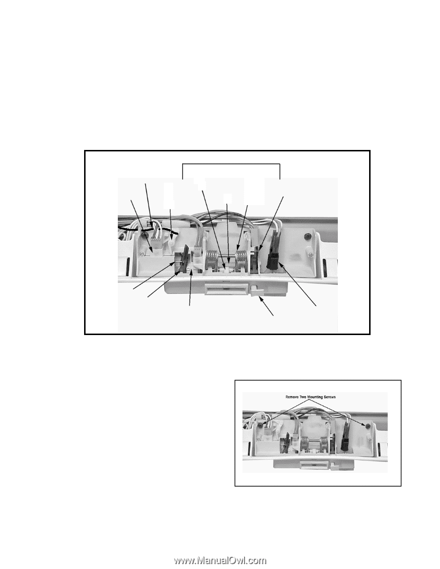
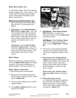
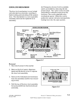
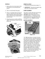
DOOR LOCK MECHANISM The door lock mechanism is now locked and unlocked via solenoids, resulting in faster locking and unlocking of the washer door. The mechanism is a non-repairable assembly and must be replaced as an assembly. An Emergency Access Cord is available and is accessible by removing the dispenser bezel. The nylon cord is located and pulled in a direction away from the lock area. The cord is attached to the mechanical opener. When the cord is pulled, the opener will pivot and push the locking lever into the open positon. DOOR LOCK MECHANISM Door Emergency Cord Rotating Cam Lock/Unlock Solenoid Mechanical Opener Cam Support Door Lock Spring Door Open/Closed Switch Solenoid Push-Rod Locking Lever Door Lock/ Unlock Switch Lamp Socket Door Actuator & Lamp Figure 5-7 Removal 1. Disconnect power to the washer. 2. Remove the front panel, dispenser bezel and lift the top cover to expose the door lock assembly. 3. Remove the individual wire harnesses from the assembly and the two mounting screws. 4. Roll the top of the door lock assembly forward and lift from the front shroud assembly. Figure 5-8 16010486 (16008373-05) Revised 10/00 Section 5. Teardown & Wiring Information ©2001 Maytag Appliances Sales Company 5-3
-
 1
1 -
2
-
3
-
4
-
5
-
6
-
7
-
8
-
9
-
10
-
11
-
12
-
13
-
14
-
15
-
16
-
17
-
18
-
19
-
20
-
21
-
22
-
23
-
24
-
25
-
26
-
27
-
28
-
29
-
30
-
31
-
32
-
33
-
34
-
35
-
36
-
37
-
38
-
39
-
40
-
41
-
42
-
43
-
44
-
45
-
46
-
47
-
48
-
49
-
50
-
51
-
52
-
53
-
54
-
55
-
56
-
57
-
58
-
59
-
60
-
61
-
62
-
63
-
64
-
65
-
66
-
67
-
68
-
69
-
70
-
71
-
72
-
73
-
74
-
75
-
76
-
77
-
78
-
79
-
80
-
81
-
82
-
83
-
84
-
85
-
86
-
87
-
88
-
89
-
90
-
91
-
92
-
93
-
94
-
95
-
96
-
97
-
98
-
99
-
100
-
101
-
102
-
103
-
104
-
105
-
106
-
107
-
108
-
109
-
110
-
111
-
112
-
113
-
114
-
115
-
116
-
117
-
118
-
119
-
120
-
121
-
122
-
123
-
124
-
125
-
126
-
127
-
128
-
129
-
130
-
131
-
132
-
133
-
134
-
135
-
136
-
137
-
138
-
139
-
140
-
141
-
142
-
143
-
144
-
145
-
 146
146 -
 147
147 -
 148
148 -
 149
149 -
 150
150 -
 151
151 -
 152
152 -
 153
153 -
 154
154 -
 155
155 -
 156
156 -
157
 |
 |