Maytag MAH5500BWW Service Manual - Page 152
Rear Access Panel - mold
 |
View all Maytag MAH5500BWW manuals
Add to My Manuals
Save this manual to your list of manuals |
Page 152 highlights
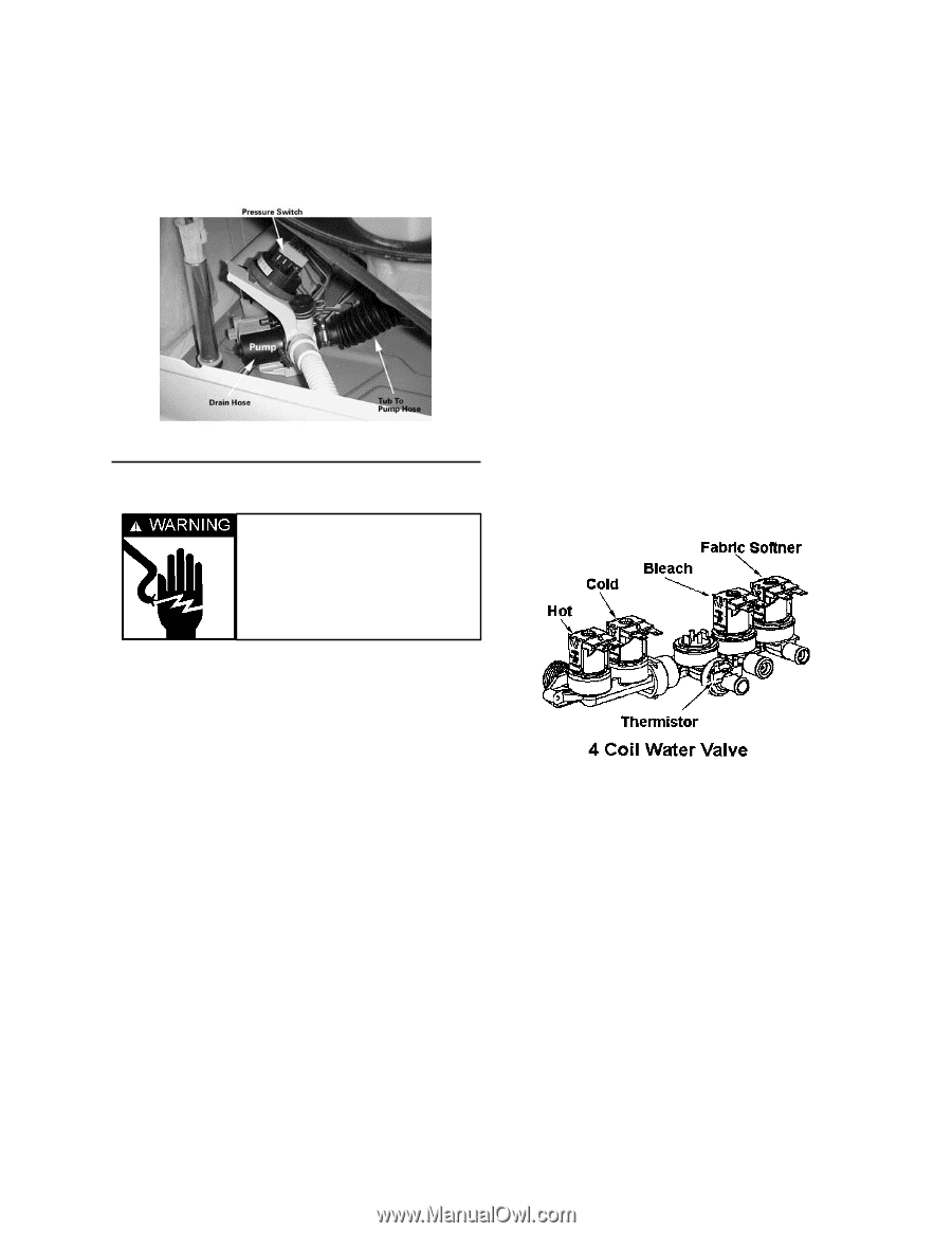
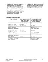
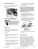
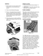
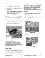
REAR ACCESS PANEL Removal of the access panel gains access to the rear components of the washer (Figure 5-9). 5. Locate and loosen the valve mounting screw by turning the screw at least three full turns. NOTE: The mounting screw serves as a locating pin to hold the valve in position on the mounting bracket. By partially removing the screw, the water valve can now be slid to the left and removed from the bracket (Figure 5-10). Figure 5-9 WATER SYSTEM COMPONENTS Warning - Always shut off electrical power to the unit before beginning any service repair procedures. 6. Carefully lift the valve with the inlet hoses attached and direct the inlet hoses through the openings in the valve mounting bracket. 7. The hoses can be crimped or the water shut off at the faucets. Place a towel below the valve and remove the inlet hoses from the water valve. WATER VALVE The water valve is accessible from the front of the machine. The flow rate of the valve is 4 gpm. Removal 8. To reinstall, reverse the aforementioned procedure. 1. Discontinue power and water to the machine. PRESSURE SWITCH 2. Remove the front panel and lift the top cover. The pressure switch was relocated from the console and mounted to a bracket extension molded as part of the pump 3. Remove the wire harness connections to the water valve solenoids. assembly. A vertical outlet on the pump has a rubber cap positioned over the outlet with a spout and is clamped into position. 4. Loosen and remove the hose clamps on the inlet hoses leading away from the water valve. The nipple of the pressure switch is inserted into the rubber spout. Pressurization in the vertical outlet of the pump actuates the pressure switch and deter- 16010486 (16008373-05) Revised 10/00 mines proper fill levels. Section 5. Teardown & Wiring Information ©2001 Maytag Appliances Sales Company 5-4
-
 1
1 -
2
-
3
-
4
-
5
-
6
-
7
-
8
-
9
-
10
-
11
-
12
-
13
-
14
-
15
-
16
-
17
-
18
-
19
-
20
-
21
-
22
-
23
-
24
-
25
-
26
-
27
-
28
-
29
-
30
-
31
-
32
-
33
-
34
-
35
-
36
-
37
-
38
-
39
-
40
-
41
-
42
-
43
-
44
-
45
-
46
-
47
-
48
-
49
-
50
-
51
-
52
-
53
-
54
-
55
-
56
-
57
-
58
-
59
-
60
-
61
-
62
-
63
-
64
-
65
-
66
-
67
-
68
-
69
-
70
-
71
-
72
-
73
-
74
-
75
-
76
-
77
-
78
-
79
-
80
-
81
-
82
-
83
-
84
-
85
-
86
-
87
-
88
-
89
-
90
-
91
-
92
-
93
-
94
-
95
-
96
-
97
-
98
-
99
-
100
-
101
-
102
-
103
-
104
-
105
-
106
-
107
-
108
-
109
-
110
-
111
-
112
-
113
-
114
-
115
-
116
-
117
-
118
-
119
-
120
-
121
-
122
-
123
-
124
-
125
-
126
-
127
-
128
-
129
-
130
-
131
-
132
-
133
-
134
-
135
-
136
-
137
-
138
-
139
-
140
-
141
-
142
-
143
-
144
-
145
-
146
-
 147
147 -
 148
148 -
 149
149 -
 150
150 -
 151
151 -
 152
152 -
 153
153 -
 154
154 -
 155
155 -
 156
156 -
 157
157
 |
 |