Maytag MAH5500BWW Service Manual - Page 153
Pump Assembly, Heater Assembly - parts manual
 |
View all Maytag MAH5500BWW manuals
Add to My Manuals
Save this manual to your list of manuals |
Page 153 highlights
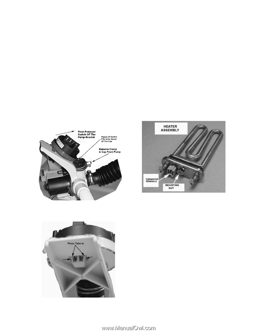
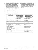
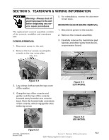
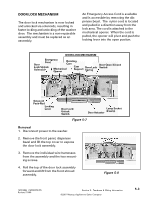
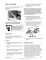
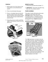
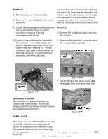
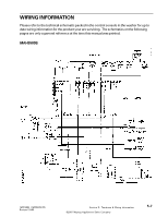
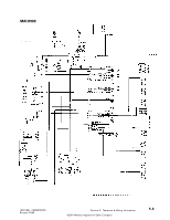
REMOVAL 1. Remove the rear access panel or the front panel to access the pressure switch. REINSTALLATION 1. Reverse the aforementioned steps 1-4. 2. IMPORTANT: Reposition the plastic bag back onto the pressure switch. 2. Place a towel beneath the pump. PUMP ASSEMBLY 3. Remove the plastic bag covering the pressure switch. Press in the locking tabs on the back of the pressure switch and pivot the pressure switch off the pump bracket. 4. Grasp the pressure switch and lift the nipple of the pressure switch from the pump cap. The pump is rated at 80 watts and mounts identically to the pump used in the MAH3000 washer. The pressure switch mounting bracket is a molded part of the pump housing. For removal instructions, see page 6-4 in the 16008373 manual. HEATER ASSEMBLY Figure 5-11 Figure 5-12 Figure 5-13 The 1000 watt heater is located in the tub cover below the door openning and above the sump area of the washer. A thermistor on the heater regulates the temperature of the heater to maintain proper water temperature when selected. The heater is secured to the tub cover by means of rubber compression. An inner mounting plate is located opposite of the external mounting plate with a layer of rubber between. When the nut is secured, the rubber is compressed and expands to seal the heater entry hole in the tub cover. Heater resistance is 14 ohms. 16010486 (16008373-05) Revised 10/00 Section 5. Teardown & Wiring Information ©2001 Maytag Appliances Sales Company 5-5
-
 1
1 -
2
-
3
-
4
-
5
-
6
-
7
-
8
-
9
-
10
-
11
-
12
-
13
-
14
-
15
-
16
-
17
-
18
-
19
-
20
-
21
-
22
-
23
-
24
-
25
-
26
-
27
-
28
-
29
-
30
-
31
-
32
-
33
-
34
-
35
-
36
-
37
-
38
-
39
-
40
-
41
-
42
-
43
-
44
-
45
-
46
-
47
-
48
-
49
-
50
-
51
-
52
-
53
-
54
-
55
-
56
-
57
-
58
-
59
-
60
-
61
-
62
-
63
-
64
-
65
-
66
-
67
-
68
-
69
-
70
-
71
-
72
-
73
-
74
-
75
-
76
-
77
-
78
-
79
-
80
-
81
-
82
-
83
-
84
-
85
-
86
-
87
-
88
-
89
-
90
-
91
-
92
-
93
-
94
-
95
-
96
-
97
-
98
-
99
-
100
-
101
-
102
-
103
-
104
-
105
-
106
-
107
-
108
-
109
-
110
-
111
-
112
-
113
-
114
-
115
-
116
-
117
-
118
-
119
-
120
-
121
-
122
-
123
-
124
-
125
-
126
-
127
-
128
-
129
-
130
-
131
-
132
-
133
-
134
-
135
-
136
-
137
-
138
-
139
-
140
-
141
-
142
-
143
-
144
-
145
-
146
-
147
-
 148
148 -
 149
149 -
 150
150 -
 151
151 -
 152
152 -
 153
153 -
 154
154 -
 155
155 -
 156
156 -
 157
157
 |
 |