Maytag MAH5500BWW Service Manual - Page 154
REMOVAL, Thermistor Removal, SUMP COVER
 |
View all Maytag MAH5500BWW manuals
Add to My Manuals
Save this manual to your list of manuals |
Page 154 highlights
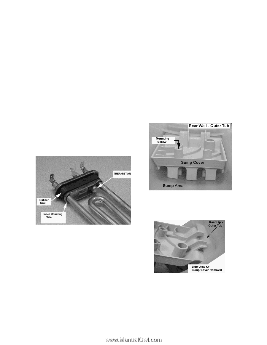
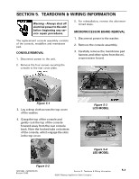
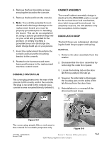
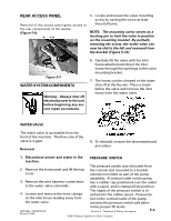
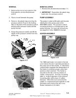
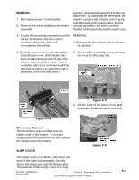
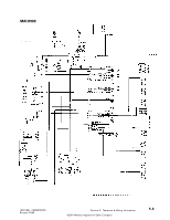
REMOVAL 1. Disconnect power to the washer. 2. Remove the wires leading to the heater assembly. ture the detergent dispensed into the top dispenser. By capturing the detergent, the washer can provide a better mix of water and detergent in the wash water. During normal operation, the sump cover is flushed of detergent during the wash cycle. 3. Locate the mounting nut and loosen the nut by turning the nut in a counter clockwise direction. This will uncompress the rubber. REMOVAL 1. Remove the front panel, tub cover and the spinner. 4. Carefully remove the heater assembly from the tub cover. (If the heater has been in place for a period of time, the rubber may have taken a set. Then a complete tub cover removal would be deemed necessary to push the heater assembly out of the tub cover.) 2. Remove the mounting screw securing the cover to the outer tub. Figure 5-15 3. Lift the front of the sump cover and disengage from rear lip of outer tub. Figure 5-14 Thermistor Removal The thermistor is press fitted into the rubber seal of the heater. To remove, simply push the thermistor out and reinsert the replacement thermistor. SUMP COVER Figure 5-16 The sump cover is located in the lower rear area of the outer tub assembly, directly above the sump area and the drain outlet. The purpose of the sump cover is to cap- 16010486 (16008373-05) Revised 10/00 Section 5. Teardown & Wiring Information ©2001 Maytag Appliances Sales Company 5-6
-
 1
1 -
2
-
3
-
4
-
5
-
6
-
7
-
8
-
9
-
10
-
11
-
12
-
13
-
14
-
15
-
16
-
17
-
18
-
19
-
20
-
21
-
22
-
23
-
24
-
25
-
26
-
27
-
28
-
29
-
30
-
31
-
32
-
33
-
34
-
35
-
36
-
37
-
38
-
39
-
40
-
41
-
42
-
43
-
44
-
45
-
46
-
47
-
48
-
49
-
50
-
51
-
52
-
53
-
54
-
55
-
56
-
57
-
58
-
59
-
60
-
61
-
62
-
63
-
64
-
65
-
66
-
67
-
68
-
69
-
70
-
71
-
72
-
73
-
74
-
75
-
76
-
77
-
78
-
79
-
80
-
81
-
82
-
83
-
84
-
85
-
86
-
87
-
88
-
89
-
90
-
91
-
92
-
93
-
94
-
95
-
96
-
97
-
98
-
99
-
100
-
101
-
102
-
103
-
104
-
105
-
106
-
107
-
108
-
109
-
110
-
111
-
112
-
113
-
114
-
115
-
116
-
117
-
118
-
119
-
120
-
121
-
122
-
123
-
124
-
125
-
126
-
127
-
128
-
129
-
130
-
131
-
132
-
133
-
134
-
135
-
136
-
137
-
138
-
139
-
140
-
141
-
142
-
143
-
144
-
145
-
146
-
147
-
148
-
 149
149 -
 150
150 -
 151
151 -
 152
152 -
 153
153 -
 154
154 -
 155
155 -
 156
156 -
 157
157
 |
 |