Maytag MAH5500BWW Service Manual - Page 23
Timer & Console Switches, Timer Input Charts - wax motor
 |
View all Maytag MAH5500BWW manuals
Add to My Manuals
Save this manual to your list of manuals |
Page 23 highlights
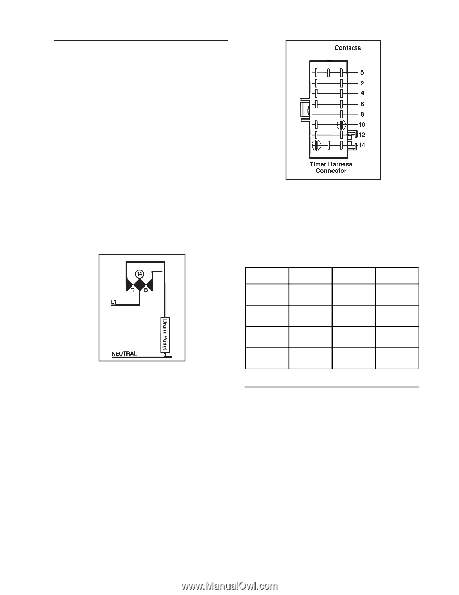
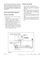
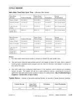
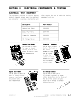
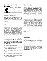
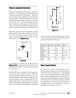
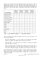
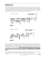
Timer & Console Switches The timer is located in the control console on the back. It is composed of a series of switches driven by an electric timer motor. The timer motor rotates a pinion gear which then rotates internal cams. As the cams rotate, they lift and drop various switch contacts which ride on the cam. The internal switches provide cycle sequence or step inputs to the machine control to control the pump, dispenser wax motors, delay light, ON light and timer motor. The timer wire harness connector can be pulled and the individual contacts for the various circuits can be checked with an ohm meter. As illustrated, timer contact for the drain pump is 14T (Figure 2-1). TCB Figure 2-2 motor windings. The following chart can be used for checking other components via the timer wire harness connector. Figure 2-1 You can identify the wire for the drain circuit (Figure 2-2) by tracing down the side of the connector to contact 14, and across to align with column T. Contact 8B in the connector is a direct contact to the neutral leg of the timer. When an ohm meter probe is placed into the 14T connection and the other probe is placed into 8B, an ohm reading of the complete drain circuit can be performed. The drain circuit should have a resistance of approximately 18 ohms. This is the resistance reading of the pump Description Connector Connector Ohms Pump Motor 14T 10B 18 Bleach Wax Motor 2B 10B 950-1100 Softener Wax Motor 2T 10B 950-1100 Timer Motor 10T 10B 5000 Timer Input Charts As stated previously, the machine control board receives inputs from the timer monitor where the timer is in the cycle. The machine control board accomplishes this by routing four circuits through the timer. Two of the circuits (1A & 1B) are supplied with 120 VAC and the other two circuits (2A & 2B) are 24 VDC. The voltages for the four circuits is shown on the timer chart of the electrical schematic enclosed in the washer console. 16008373-01 SECTION 2. ELECTRICAL COMPONENTS & TESTING 2 - 3 © 1998 Maytag Corporation
-
 1
1 -
2
-
3
-
4
-
5
-
6
-
7
-
8
-
9
-
10
-
11
-
12
-
13
-
14
-
15
-
16
-
17
-
 18
18 -
 19
19 -
 20
20 -
 21
21 -
 22
22 -
 23
23 -
 24
24 -
 25
25 -
 26
26 -
 27
27 -
 28
28 -
29
-
30
-
31
-
32
-
33
-
34
-
35
-
36
-
37
-
38
-
39
-
40
-
41
-
42
-
43
-
44
-
45
-
46
-
47
-
48
-
49
-
50
-
51
-
52
-
53
-
54
-
55
-
56
-
57
-
58
-
59
-
60
-
61
-
62
-
63
-
64
-
65
-
66
-
67
-
68
-
69
-
70
-
71
-
72
-
73
-
74
-
75
-
76
-
77
-
78
-
79
-
80
-
81
-
82
-
83
-
84
-
85
-
86
-
87
-
88
-
89
-
90
-
91
-
92
-
93
-
94
-
95
-
96
-
97
-
98
-
99
-
100
-
101
-
102
-
103
-
104
-
105
-
106
-
107
-
108
-
109
-
110
-
111
-
112
-
113
-
114
-
115
-
116
-
117
-
118
-
119
-
120
-
121
-
122
-
123
-
124
-
125
-
126
-
127
-
128
-
129
-
130
-
131
-
132
-
133
-
134
-
135
-
136
-
137
-
138
-
139
-
140
-
141
-
142
-
143
-
144
-
145
-
146
-
147
-
148
-
149
-
150
-
151
-
152
-
153
-
154
-
155
-
156
-
157
 |
 |