Maytag MAH5500BWW Service Manual - Page 27
Motor Control Board, Drive Motor
 |
View all Maytag MAH5500BWW manuals
Add to My Manuals
Save this manual to your list of manuals |
Page 27 highlights
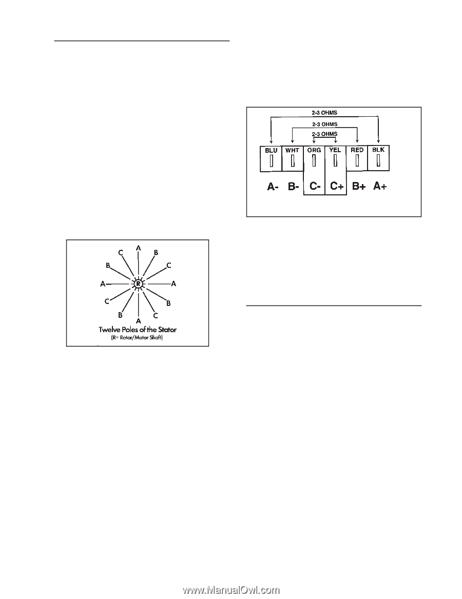
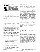
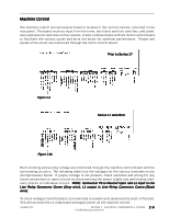
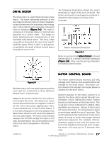
DRIVE MOTOR The drive motor is a switched reluctance type motor. The basic operating principle of the switched reluctance motor is direct magnetic attraction between the stationary electromagnetic coils (stator) and a specially configured rotor or armature (Figure 2-4). The rotor is comprised of stacked plates or laminations mounted on a center shaft. The shape of these laminations are characteristic of the switched reluctance motor. The rotor, when viewed from the end of the rotor, has "teeth" much like a gear. These "teeth", or pole pieces, are pulled as the result of direct current power through the stator coils. The following illustration shows the motor terminals for each of the coils involved. The letters with positive and negative symbols indicate the motor phase circuitry of the terminals. Motor Harness Connector Figure 2-5 Refer to section titled Motor Control for board identification of A, B and C terminal/harnesses (Figure 2-6). Also, see the wiring schematic for harness identification. MOTOR CONTROL BOARD Figure 2-4 Multiple stator coils are positioned around the rotor and are connected in three different phased "sets" of paired coils. Magnetic attraction causes the rotor poles to turn toward the coils. The electronic motor control board switches the magnetic field off as the rotor pole piece approaches; then, turns on another set of coils further ahead. It is this switching action of motor phases that determines direction and rotational speed of the rotor (and shaft). The motor control board changes the 120 VAC voltage line input to 170 VDC, and distributes the current phases to the stator coil sets in sequence to the drive motor. The motor control board receives 120 VAC voltage from the line cord and distributes DC voltage to the drive motor. The motor control converts the voltage from single phase to 3 phase for the drive motor. Another purpose of the motor control is to monitor the drive motor speed through a tachometer circuit linking the motor control board to a tachometer on the drive motor. This is a 3-wire circuit comprised of a Black, Blue and White wire harness. Failure of this circuit will cause the motor to start jerking in place or accelerate rapidly for up to 5 seconds. This occurs whenever the tachometer in the drive motor is trying to locate the proper shutter and sensor sequence. For example, if the tachometer signal is lost from the motor control to the machine control just prior to spin, the motor will ramp up for 5 seconds then stop. 16008373-01 SECTION 2. ELECTRICAL COMPONENTS & TESTING 2 - 7 © 1998 Maytag Corporation
-
 1
1 -
2
-
3
-
4
-
5
-
6
-
7
-
8
-
9
-
10
-
11
-
12
-
13
-
14
-
15
-
16
-
17
-
18
-
19
-
20
-
21
-
 22
22 -
 23
23 -
 24
24 -
 25
25 -
 26
26 -
 27
27 -
 28
28 -
 29
29 -
 30
30 -
 31
31 -
 32
32 -
33
-
34
-
35
-
36
-
37
-
38
-
39
-
40
-
41
-
42
-
43
-
44
-
45
-
46
-
47
-
48
-
49
-
50
-
51
-
52
-
53
-
54
-
55
-
56
-
57
-
58
-
59
-
60
-
61
-
62
-
63
-
64
-
65
-
66
-
67
-
68
-
69
-
70
-
71
-
72
-
73
-
74
-
75
-
76
-
77
-
78
-
79
-
80
-
81
-
82
-
83
-
84
-
85
-
86
-
87
-
88
-
89
-
90
-
91
-
92
-
93
-
94
-
95
-
96
-
97
-
98
-
99
-
100
-
101
-
102
-
103
-
104
-
105
-
106
-
107
-
108
-
109
-
110
-
111
-
112
-
113
-
114
-
115
-
116
-
117
-
118
-
119
-
120
-
121
-
122
-
123
-
124
-
125
-
126
-
127
-
128
-
129
-
130
-
131
-
132
-
133
-
134
-
135
-
136
-
137
-
138
-
139
-
140
-
141
-
142
-
143
-
144
-
145
-
146
-
147
-
148
-
149
-
150
-
151
-
152
-
153
-
154
-
155
-
156
-
157
 |
 |