Maytag MAH5500BWW Service Manual - Page 29
Motor Windings Check
 |
View all Maytag MAH5500BWW manuals
Add to My Manuals
Save this manual to your list of manuals |
Page 29 highlights
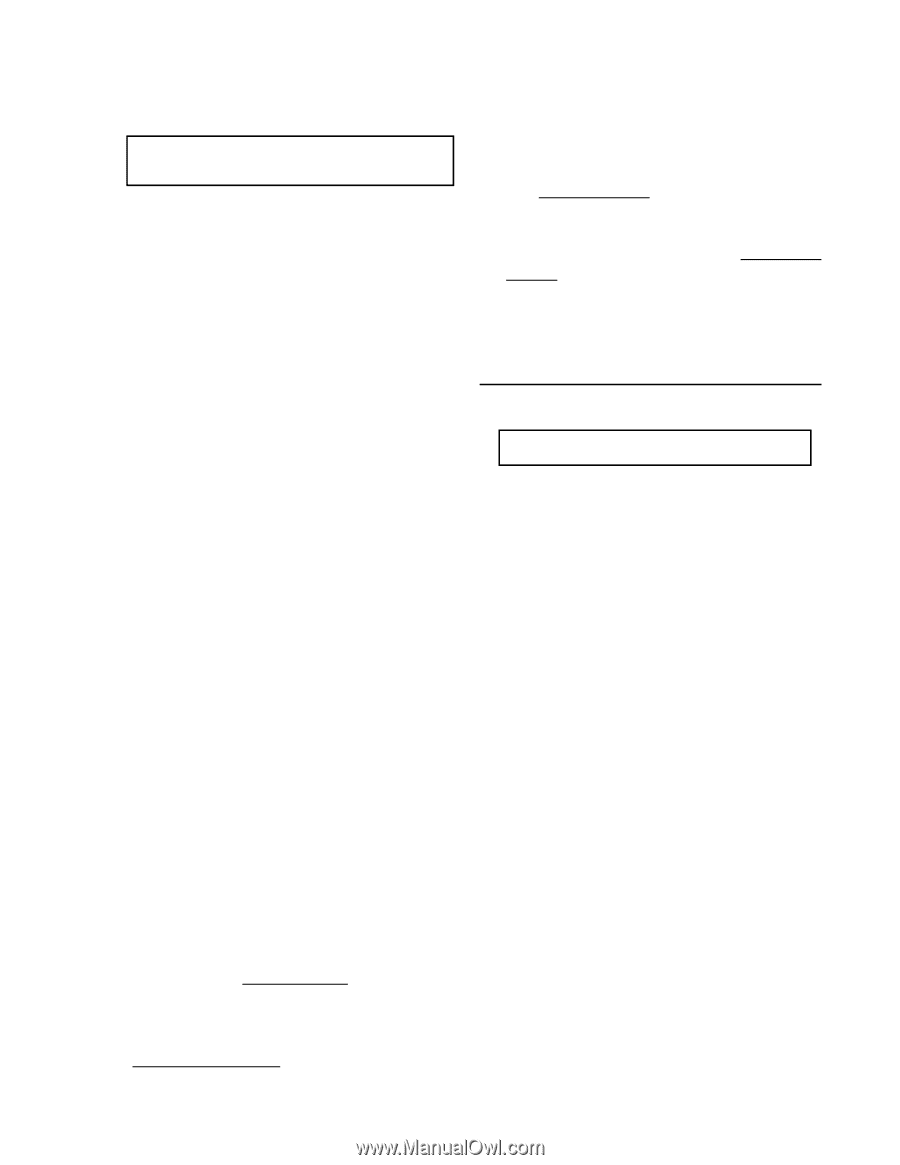
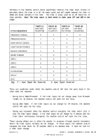
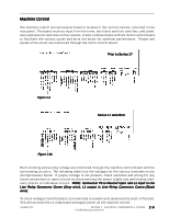
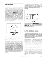
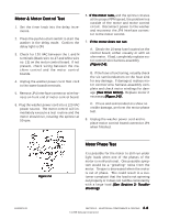
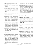
To gain access to the motor control board terminals (Figure 2-6): windings check (See Motor Windings Check). 1 . Disconnect power to the washer prior to testing. 2 . Remove the two screws securing the motor control assembly to the base. Unsnap the two twist-lock wire ties restraining the motor to the motor control board harness base. 3 . Remove the green ground wire, line & neutral wires and the JP4 connector from the motor control board. 4. Carefully lift the front end of the motor control board to disengage the rear locking tabs from the slots in the base. Slowly drag the motor control board, with motor harness attached, toward the front of the washer and place in front of the washer. 5. Remove the screw securing the splash shield covering the face of the motor control board. Pivot the splash shield with top screw in the motor control board metal frame, allowing the plastic shield to become an electrical shield between the motor control board and the base. 6 . Reconnect the ground wire, line 1 and neutral wires. Leave the JP4 connector off the board (Figure 2-6). 7 . Place the timer knob into the delay increments. 10. Check Phase B by disconnecting the white or red wire at the motor control board. If the motor operates with a slight growling sound, phases A and C are operating correctly. Reconnect phase B and test with phase A disconnected. If the motor does not run properly, phase A or C is not functioning. Perform the motor windings check (See Motor Windings Check). Motor Windings Check 1 . Disconnect power to the unit. 2 . Remove each pair of phase wires from the motor control and perform an ohm check of each wire leading to the motor. Each wire pair should show 2-3 ohms resistance (Figure 2-5). 2. There should be no continuity between any of the terminals and the frame of the motor. 3 . Check that all six motor terminals are secure and at the same height in the connector housing. Replace motor if terminals are pressed into the motor. 4. Remount the six-position motor connector onto the motor. Reassemble the drip shield cover onto the motor control. 8. Plug the power cord into the wall socket and press the push-to-start button. 9. Check Phase C by disconnecting the yellow or orange wire at the motor control board. If the motor operates with a slight growling sound, phases A and B are operating correctly. Reconnect phase C and test with phase B disconnected. If the motor does not run properly, phase A or B is not functioning. Perform the motor 5. Reposition the motor control into the washer when finished. Make sure the two screws and the twistlock wire ties are fastened properly to the wire harness. 16008373-01 SECTION 2. ELECTRICAL COMPONENTS & TESTING © 1998 Maytag Corporation 2-9
-
 1
1 -
2
-
3
-
4
-
5
-
6
-
7
-
8
-
9
-
10
-
11
-
12
-
13
-
14
-
15
-
16
-
17
-
18
-
19
-
20
-
21
-
22
-
23
-
 24
24 -
 25
25 -
 26
26 -
 27
27 -
 28
28 -
 29
29 -
 30
30 -
 31
31 -
 32
32 -
 33
33 -
 34
34 -
35
-
36
-
37
-
38
-
39
-
40
-
41
-
42
-
43
-
44
-
45
-
46
-
47
-
48
-
49
-
50
-
51
-
52
-
53
-
54
-
55
-
56
-
57
-
58
-
59
-
60
-
61
-
62
-
63
-
64
-
65
-
66
-
67
-
68
-
69
-
70
-
71
-
72
-
73
-
74
-
75
-
76
-
77
-
78
-
79
-
80
-
81
-
82
-
83
-
84
-
85
-
86
-
87
-
88
-
89
-
90
-
91
-
92
-
93
-
94
-
95
-
96
-
97
-
98
-
99
-
100
-
101
-
102
-
103
-
104
-
105
-
106
-
107
-
108
-
109
-
110
-
111
-
112
-
113
-
114
-
115
-
116
-
117
-
118
-
119
-
120
-
121
-
122
-
123
-
124
-
125
-
126
-
127
-
128
-
129
-
130
-
131
-
132
-
133
-
134
-
135
-
136
-
137
-
138
-
139
-
140
-
141
-
142
-
143
-
144
-
145
-
146
-
147
-
148
-
149
-
150
-
151
-
152
-
153
-
154
-
155
-
156
-
157
 |
 |