Maytag MAH5500BWW Service Manual - Page 31

Unbalance Control System - locked rotor

Page 31 highlights

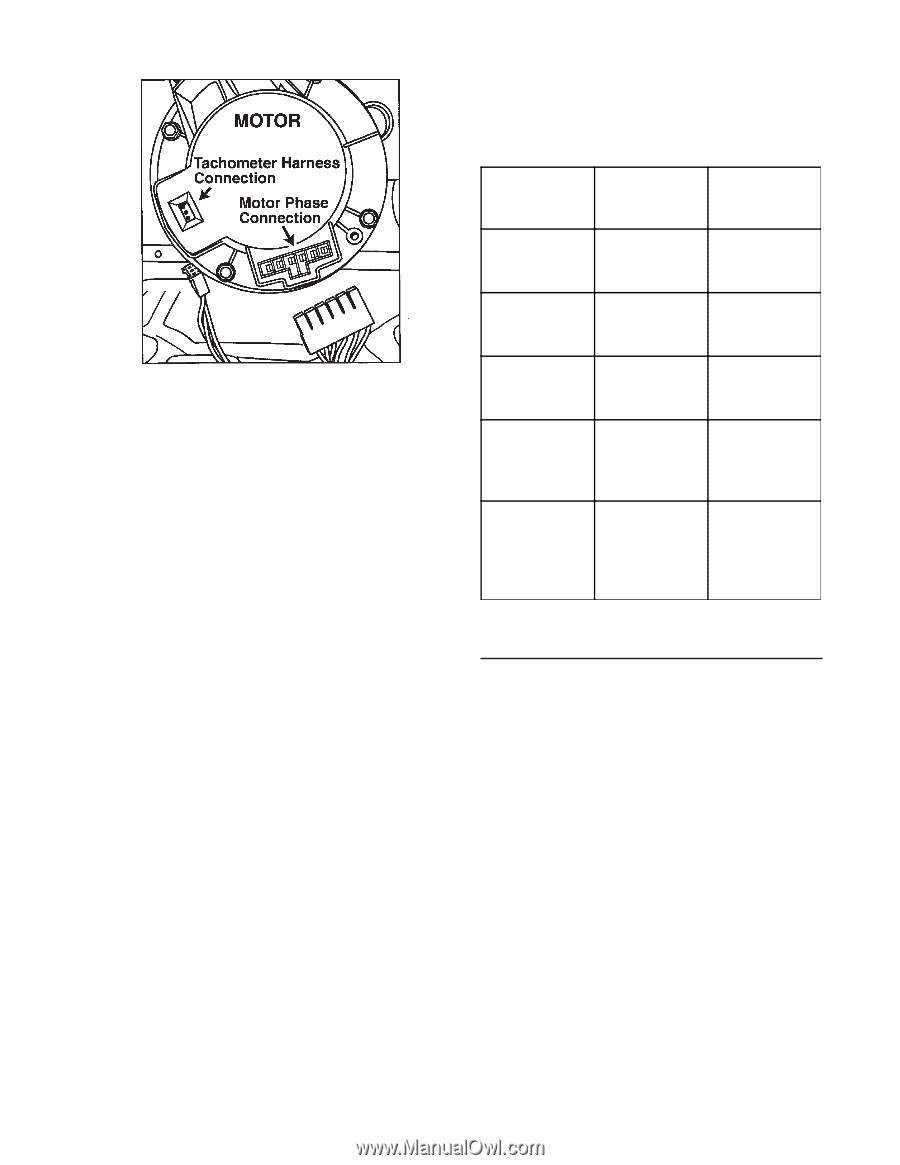
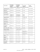
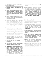
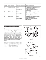
The following table indicates voltage checks of the tachometer harness between the motor and motor control board. Figure 2-11 The motor control monitors the signals and communicates this information to the machine control. The purpose of this signal is to tell the motor when to energize each winding in the motor and to tell the machine control the actual motor speed. Note: If the machine control board does not receive an input signal from the motor control/tachometer circuit (JP4 connector), the motor speed will rapidly accelerate for 5 seconds then shut down. The machine control will sense a "locked rotor" condition and the motor will stop. If the motor control does not receive an input signal from the motor, the motor will "jerk" for 5 seconds then shut down. 1. Inspect the motor control wire harness for integrity of the connections on both ends. The harness is comprised of a White, Blue and Black wire. 2. Set the washer into the Delay Wash cycle and press the start/off button. The unit will start without activating the motor. Leave the tachometer harness on the motor control and insert the meter probes into the back side of the tachommeter harness. Tachometer Wire Checks Voltage Found Condition Of Component White to Black (From Motor Control) 11 VDC (± 2.5 VDC) Good Motor Control Board White To Black (From Motor 0 VDC Control) Bad Motor Control Board White To Black (From Motor Control) + 13 VDC or

  • 1
  • 2
  • 3
  • 4
  • 5
  • 6
  • 7
  • 8
  • 9
  • 10
  • 11
  • 12
  • 13
  • 14
  • 15
  • 16
  • 17
  • 18
  • 19
  • 20
  • 21
  • 22
  • 23
  • 24
  • 25
  • 26
  • 27
  • 28
  • 29
  • 30
  • 31
  • 32
  • 33
  • 34
  • 35
  • 36
  • 37
  • 38
  • 39
  • 40
  • 41
  • 42
  • 43
  • 44
  • 45
  • 46
  • 47
  • 48
  • 49
  • 50
  • 51
  • 52
  • 53
  • 54
  • 55
  • 56
  • 57
  • 58
  • 59
  • 60
  • 61
  • 62
  • 63
  • 64
  • 65
  • 66
  • 67
  • 68
  • 69
  • 70
  • 71
  • 72
  • 73
  • 74
  • 75
  • 76
  • 77
  • 78
  • 79
  • 80
  • 81
  • 82
  • 83
  • 84
  • 85
  • 86
  • 87
  • 88
  • 89
  • 90
  • 91
  • 92
  • 93
  • 94
  • 95
  • 96
  • 97
  • 98
  • 99
  • 100
  • 101
  • 102
  • 103
  • 104
  • 105
  • 106
  • 107
  • 108
  • 109
  • 110
  • 111
  • 112
  • 113
  • 114
  • 115
  • 116
  • 117
  • 118
  • 119
  • 120
  • 121
  • 122
  • 123
  • 124
  • 125
  • 126
  • 127
  • 128
  • 129
  • 130
  • 131
  • 132
  • 133
  • 134
  • 135
  • 136
  • 137
  • 138
  • 139
  • 140
  • 141
  • 142
  • 143
  • 144
  • 145
  • 146
  • 147
  • 148
  • 149
  • 150
  • 151
  • 152
  • 153
  • 154
  • 155
  • 156
  • 157

© 1998 Maytag Corporation
2-11
2-11
2-11
2-11
2-11
16008373-01
SECTION 2.
ELECTRICAL COMPONENTS & TESTING
The motor control monitors the signals and
communicates this information to the ma-
chine control.
The purpose of this signal is to
tell the motor when to energize each winding
in the motor and to tell the machine control
the actual motor speed.
Note:
Note:
Note:
Note:
Note:
If the machine control board does not
receive an input signal from the motor con-
trol/tachometer circuit (JP4 connector), the
motor speed will rapidly accelerate for 5 sec-
onds then shut down.
The machine control
onds then shut down.
The machine control
onds then shut down.
The machine control
onds then shut down.
The machine control
onds then shut down.
The machine control
will sense a "locked rotor" condition and the
motor will stop.
If the motor control does
motor will stop.
If the motor control does
motor will stop.
If the motor control does
motor will stop.
If the motor control does
motor will stop.
If the motor control does
not r
not r
not r
not r
not r
eceive an input signal fr
om the motor
om the motor
om the motor
om the motor
om the motor
,
the motor will "jerk" for 5 seconds then shut
down.
down.
down.
down.
down.
1.
Inspect the motor control wire harness for
integrity of the connections on both ends.
The harness is comprised of a White, Blue
and Black wire.
2.
Set the washer into the Delay Wash cycle
and press the start/off button.
The unit will
start without activating the motor.
Leave
the tachometer harness on the motor con-
trol and insert the meter probes into the
back side of the tachommeter harness.
Figure 2-11
Figure 2-11
Figure 2-11
Figure 2-11
Figure 2-11
Tachometer
Wire Checks
Voltage Found
Condition Of
Component
White to Black
(From Motor
Control)
11 VDC
(± 2.5 VDC)
Good Motor
Control Board
White To Black
(From Motor
Control)
0 VDC
Bad Motor
Control Board
White To Black
(From Motor
Control)
+ 13 VDC or
<9 VDC
Bad Motor
Blue to Black
(From Drive
Motor)
No change in
DC volts as
motor is turned
slowly
Bad Motor
Blue to Black
(From Drive
Motor)
Voltage
changes from 0
- 5 VDC volts as
motor is turned
slowly.
Good Motor
UNBALANCE CONTROL SYSTEM
The unbalance control system is comprised
of the inertial switch, outer tub displacement
switch, strut displacement switch and a cabi-
net vibration sensor mounted to the machine
control board.
The three switches are wired
in series on a 24 VDC circuit, monitored by
the machine control board.
The sensor is
mounted on the machine control board.
Software in the machine control board will
begin monitoring the switches when the spin
speed reaches 90 rpm.
The inertial unbalance
switch monitors outer tub vibrations above
150 rpm.
Inside the door is a cabinet vibra-
tion absorber designed to counter the vibra-
tion of the tub and serve as a tuned absorber
for the whole washer.
The following table indicates voltage checks
of the tachometer harness between the mo-
tor and motor control board.