Maytag MAH5500BWW Service Manual - Page 32
Strut Displacement Switch, Tub Displacement Switch - unbalance switch
 |
View all Maytag MAH5500BWW manuals
Add to My Manuals
Save this manual to your list of manuals |
Page 32 highlights
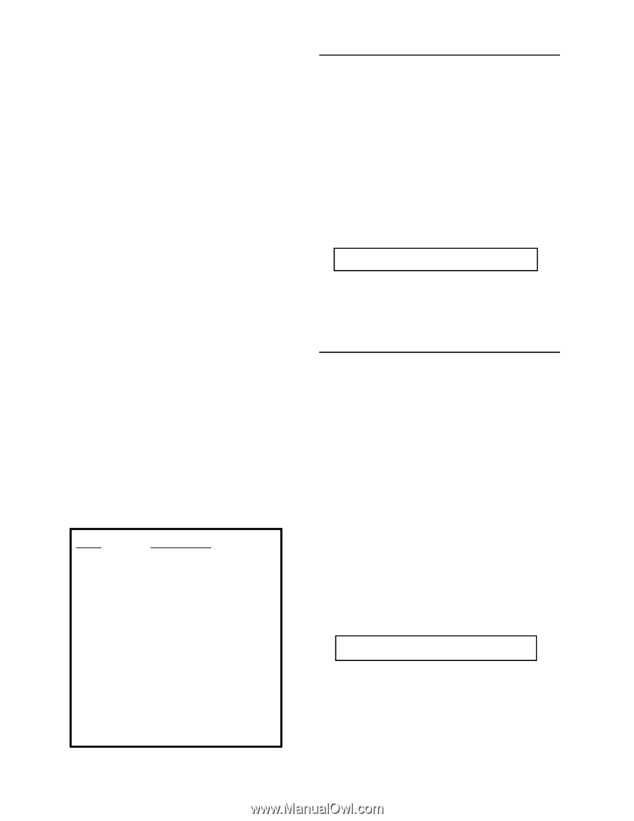
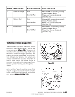
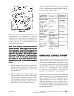
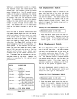
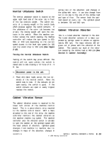
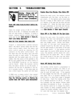
Whenever a displacement switch is tripped, the machine stops and redistributes the clothes load. This involves a three (3) second pause, followed by a five (5) second reverse tumble (47-49 rpm) to redistribute the clothes load. The washer will pause again for three (3) seconds, then start the distribution profile again. To redistribute the load, the machine tumbles the load (50-90 rpm) and again attempts to pass through critical (about 150 rpm). The machine will try to redistribute twice as the washer attempts to spin at 800 rpm. Tub Displacement Switch The tub displacement switch is located on the upper right hand side of the outer tub, below the top concrete weight, between the outer tub and the cabinet. The switch senses the outer tub touching the cabinet side as the machine passes through critical. When this switch is tripped, the machine stops and redistributes the load. Testing the Tub Displacement Switch: Once the load is properly redistributed and the speed reaches above 500 rpm, the inertial switch and cabinet vibration sensor are used. If the inertial switch or sensor is activated, the washer will drop in spin speed. This is based upon the speed at which switch activation takes place. See Figure 2-12 outlining the spin speed categories and the corresponding reduced speeds. If the switches are not activated, the final spin speed will reach a maximum of 850 rpm and then drop to find the optimum performance level, based upon readings taken by the cabinet vibration sensor. Consumers may be confused by the upand-down cycling of the motor. However, the machine is searching for the optimal speed performance. RPM FUNCTION 4 7 T u m b l e 47-85 Distribution 90-250 Accelerate Through Critical 250-499 Accelerate Through Critical 500-575 High Speed Acceleration - WILL DROP TO 450 RPM 600-675 High Speed Acceleration - WILL DROP TO 555 RPM > 6 7 5 High Speed Acceleration - WILL DROP TO 650 RPM 750-800 TOP SPIN SPEED 1 . Disconnect power to the unit. 2 . Place ohm meter leads across the two terminals of the switch. Depress the button on the switch. If the contacts open, the switch is good. If not, replace the switch. Strut Displacement Switch The strut displacement switch is clipped to the top of the left rear strut. The switch senses the outer tub bottoming out on the strut as the machine accelerates above 90 rpm. This is caused by the twisting motion of the outer tub. This additional switch is required because the twisting motion may not trip the outer tub displacement switch. The primary cause for activation would be an unbalance at the front and rear of the spinner on opposite sides. The strut displacement switch is wired in series with the tub displacement switch and causes the same type of redistribution. Testing the Strut Displacement Switch: 1 . Disconnect power to the unit. 2 . Place ohm meter leads across the two terminals of the switch. Depress the button on the switch. If the contacts close, the switch is good. If not, replace the switch. 16008373-01 Figure 2-12 SECTION 2. ELECTRICAL COMPONENTS & TESTING © 1998 Maytag Corporation 2-12
-
 1
1 -
2
-
3
-
4
-
5
-
6
-
7
-
8
-
9
-
10
-
11
-
12
-
13
-
14
-
15
-
16
-
17
-
18
-
19
-
20
-
21
-
22
-
23
-
24
-
25
-
26
-
 27
27 -
 28
28 -
 29
29 -
 30
30 -
 31
31 -
 32
32 -
 33
33 -
 34
34 -
 35
35 -
 36
36 -
 37
37 -
38
-
39
-
40
-
41
-
42
-
43
-
44
-
45
-
46
-
47
-
48
-
49
-
50
-
51
-
52
-
53
-
54
-
55
-
56
-
57
-
58
-
59
-
60
-
61
-
62
-
63
-
64
-
65
-
66
-
67
-
68
-
69
-
70
-
71
-
72
-
73
-
74
-
75
-
76
-
77
-
78
-
79
-
80
-
81
-
82
-
83
-
84
-
85
-
86
-
87
-
88
-
89
-
90
-
91
-
92
-
93
-
94
-
95
-
96
-
97
-
98
-
99
-
100
-
101
-
102
-
103
-
104
-
105
-
106
-
107
-
108
-
109
-
110
-
111
-
112
-
113
-
114
-
115
-
116
-
117
-
118
-
119
-
120
-
121
-
122
-
123
-
124
-
125
-
126
-
127
-
128
-
129
-
130
-
131
-
132
-
133
-
134
-
135
-
136
-
137
-
138
-
139
-
140
-
141
-
142
-
143
-
144
-
145
-
146
-
147
-
148
-
149
-
150
-
151
-
152
-
153
-
154
-
155
-
156
-
157
 |
 |